2011 NISSAN TIIDA fuse box location
[x] Cancel search: fuse box locationPage 403 of 3787
![NISSAN TIIDA 2011 Service Repair Manual AV-6
< SERVICE INFORMATION >[AUDIO WITHOUT NAVIGATION]
AUDIO
AUDIO
Component Parts LocationINFOID:0000000006217254
iPod® is a trademark of Apple inc., registered in the U.S. and other countries.
Syst NISSAN TIIDA 2011 Service Repair Manual AV-6
< SERVICE INFORMATION >[AUDIO WITHOUT NAVIGATION]
AUDIO
AUDIO
Component Parts LocationINFOID:0000000006217254
iPod® is a trademark of Apple inc., registered in the U.S. and other countries.
Syst](/manual-img/5/57396/w960_57396-402.png)
AV-6
< SERVICE INFORMATION >[AUDIO WITHOUT NAVIGATION]
AUDIO
AUDIO
Component Parts LocationINFOID:0000000006217254
iPod® is a trademark of Apple inc., registered in the U.S. and other countries.
System DescriptionINFOID:0000000005931275
BASE SYSTEM
Refer to Owner's Manual for audio system operating instructions.
Power is supplied at all times
• through 20A fuse (No. 27, located in the fuse and fusible link box)
1. Combination meter M24
2. Steering wheel audio control switch-
es (with Bluetooth) 3. iPod® adapter M49 (premium sys-
tem)
4. iPod® side M50 (premium system) 5. Audio unit M43 (base system) Audio unit M40, M43, M44 (premium
system)6. Front door speaker LH D12, RH
D112
7. Rear door speaker LH D207, RH D307 8. Front tweeter LH M46, RH M47 (pre-
mium system) (view with front pillar
garnish removed) 9. Bluetooth antenna (hatchback) [view
with luggage side lower finisher (RH)
removed]
10. Bluetooth control unit B121, B122 (hatchback) 11. Bluetooth antenna (sedan) (view
with trunk side finisher RH removed) 12. Bluetooth control unit B121, B122
(sedan)
AWNIA2088ZZ
Revision: May 2010 2011 Versa
Page 568 of 3787
BL-58
< SERVICE INFORMATION >
REMOTE KEYLESS ENTRY SYSTEM
REMOTE KEYLESS ENTRY SYSTEM
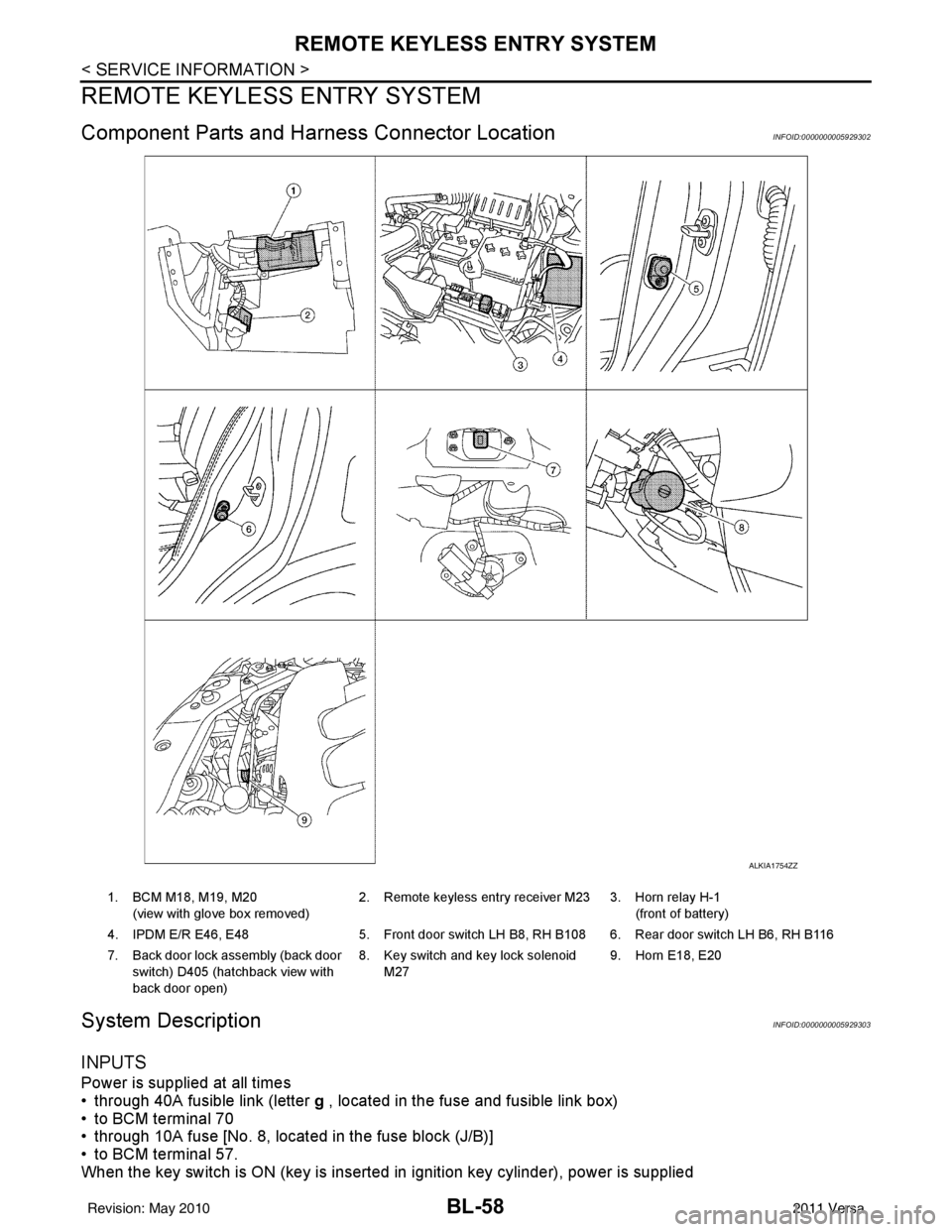
Component Parts and Harness Connector LocationINFOID:0000000005929302
System DescriptionINFOID:0000000005929303
INPUTS
Power is supplied at all times
• through 40A fusible link (letter g , located in the fuse and fusible link box)
• to BCM terminal 70
• through 10A fuse [No. 8, located in the fuse block (J/B)]
• to BCM terminal 57.
When the key switch is ON (key is inserted in ignition key cylinder), power is supplied
ALKIA1754ZZ
1. BCM M18, M19, M20
(view with glove box removed) 2. Remote keyless entry receiver M23 3. Horn relay H-1
(front of battery)
4. IPDM E/R E46, E48 5. Front door switch LH B8, RH B108 6. Rear door switch LH B6, RH B116
7. Back door lock assembly (back door switch) D405 (hatchback view with
back door open) 8. Key switch and key lock solenoid
M27 9. Horn E18, E20
Revision: May 2010
2011 Versa
Page 683 of 3787
BACK DOOR LOCKBL-173
< SERVICE INFORMATION >
C
DE
F
G H
J
K L
M A
B
BL
N
O P
BACK DOOR LOCK
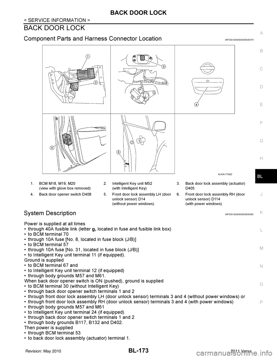
Component Parts and Har ness Connector LocationINFOID:0000000005929379
System DescriptionINFOID:0000000005929380
Power is supplied at all times
• through 40A fusible link (letter g, located in fuse and fusible link box)
• to BCM terminal 70
• through 10A fuse [No. 8, located in fuse block (J/B)]
• to BCM terminal 57
• through 10A fuse [No. 31, located in fuse block (J/B)]
• to Intelligent Key unit terminal 11 (if equipped).
Ground is supplied
• to BCM terminal 67 and
• to Intelligent Key unit terminal 12 (if equipped)
• through body grounds M57 and M61.
When back door opener switch is ON (pushed), ground is supplied
• to BCM terminal 30 (without Intelligent Key)
• through back door opener switch terminals 1 and 2
• through front door lock assembly LH (door unlock sensor) terminals 3 and 4 (without power windows) or
• through front door lock assembly RH (door unlock sensor) terminals 3 and 4 (with power windows)
• through body grounds M57 and M61
• to Intelligent Key unit terminal 24 (if equipped)
• through back door opener switch terminals 1 and 2
• through body grounds B117, B132 and D402.
Then power is supplied
• through BCM terminal 53
• to back door lock assembly (actuator) terminal 1.
ALKIA1776ZZ
1. BCM M18, M19, M20
(view with glove box removed) 2. Intelligent Key unit M52
(with Intelligent Key) 3. Back door lock assembly (actuator)
D405
4. Back door opener switch D408 5. Front door lock assembly LH (door unlock sensor) D14
(without power windows)6. Front door lock assembly RH (door
unlock sensor) D114
(with power windows)
Revision: May 2010 2011 Versa
Page 708 of 3787
BL-198
< SERVICE INFORMATION >
TRUNK LID OPENER
TRUNK LID OPENER
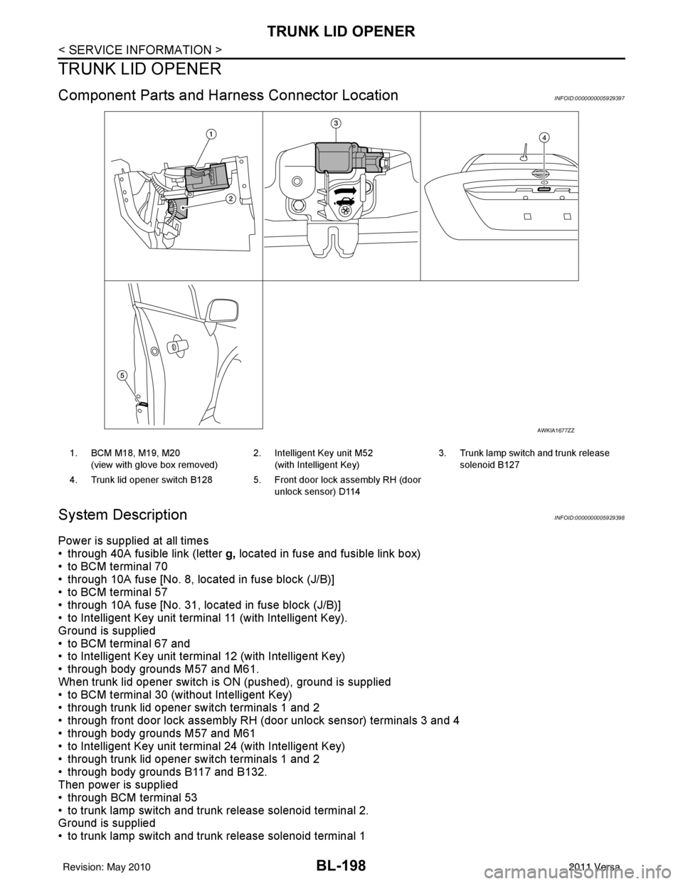
Component Parts and Harness Connector LocationINFOID:0000000005929397
System DescriptionINFOID:0000000005929398
Power is supplied at all times
• through 40A fusible link (letter g, located in fuse and fusible link box)
• to BCM terminal 70
• through 10A fuse [No. 8, located in fuse block (J/B)]
• to BCM terminal 57
• through 10A fuse [No. 31, located in fuse block (J/B)]
• to Intelligent Key unit terminal 11 (with Intelligent Key).
Ground is supplied
• to BCM terminal 67 and
• to Intelligent Key unit terminal 12 (with Intelligent Key)
• through body grounds M57 and M61.
When trunk lid opener switch is ON (pushed), ground is supplied
• to BCM terminal 30 (without Intelligent Key)
• through trunk lid opener switch terminals 1 and 2
• through front door lock assembly RH (door unlock sensor) terminals 3 and 4
• through body grounds M57 and M61
• to Intelligent Key unit terminal 24 (with Intelligent Key)
• through trunk lid opener switch terminals 1 and 2
• through body grounds B117 and B132.
Then power is supplied
• through BCM terminal 53
• to trunk lamp switch and trunk release solenoid terminal 2.
Ground is supplied
• to trunk lamp switch and trunk release solenoid terminal 1
AWKIA1677ZZ
1. BCM M18, M19, M20
(view with glove box removed) 2. Intelligent Key unit M52
(with Intelligent Key) 3. Trunk lamp switch and trunk release
solenoid B127
4. Trunk lid opener switch B128 5. Front door lock assembly RH (door unlock sensor) D114
Revision: May 2010 2011 Versa
Page 1282 of 3787
WARNING CHIMEDI-43
< SERVICE INFORMATION >
C
DE
F
G H
I
J
L
M A
B
DI
N
O P
WARNING CHIME
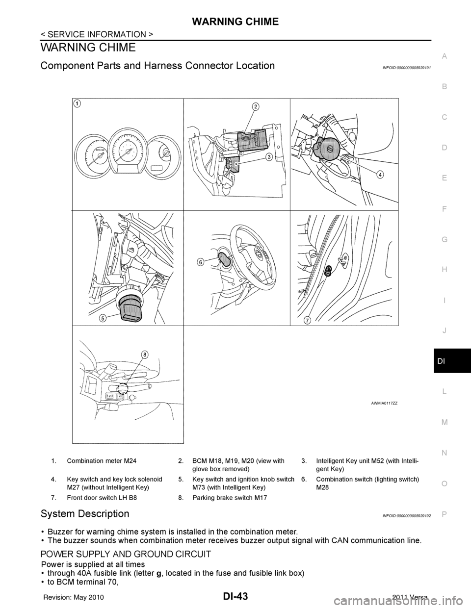
Component Parts and Har ness Connector LocationINFOID:0000000005929191
System DescriptionINFOID:0000000005929192
• Buzzer for warning chime system is installed in the combination meter.
• The buzzer sounds when combination meter receives buzzer output signal with CAN communication line.
POWER SUPPLY AND GROUND CIRCUIT
Power is supplied at all times
• through 40A fusible link (letter g, located in the fuse and fusible link box)
• to BCM terminal 70,
1. Combination meter M24 2. BCM M18, M19, M20 (view with
glove box removed) 3. Intelligent Key unit M52 (with Intelli-
gent Key)
4. Key switch and key lock solenoid M27 (without Intelligent Key) 5. Key switch and ignition knob switch
M73 (with Intelligent Key) 6. Combination switch (lighting switch)
M28
7. Front door switch LH B8 8. Parking brake switch M17
AWMIA0117ZZ
Revision: May 2010 2011 Versa
Page 2720 of 3787
GI-16
< SERVICE INFORMATION >
HOW TO USE THIS MANUAL
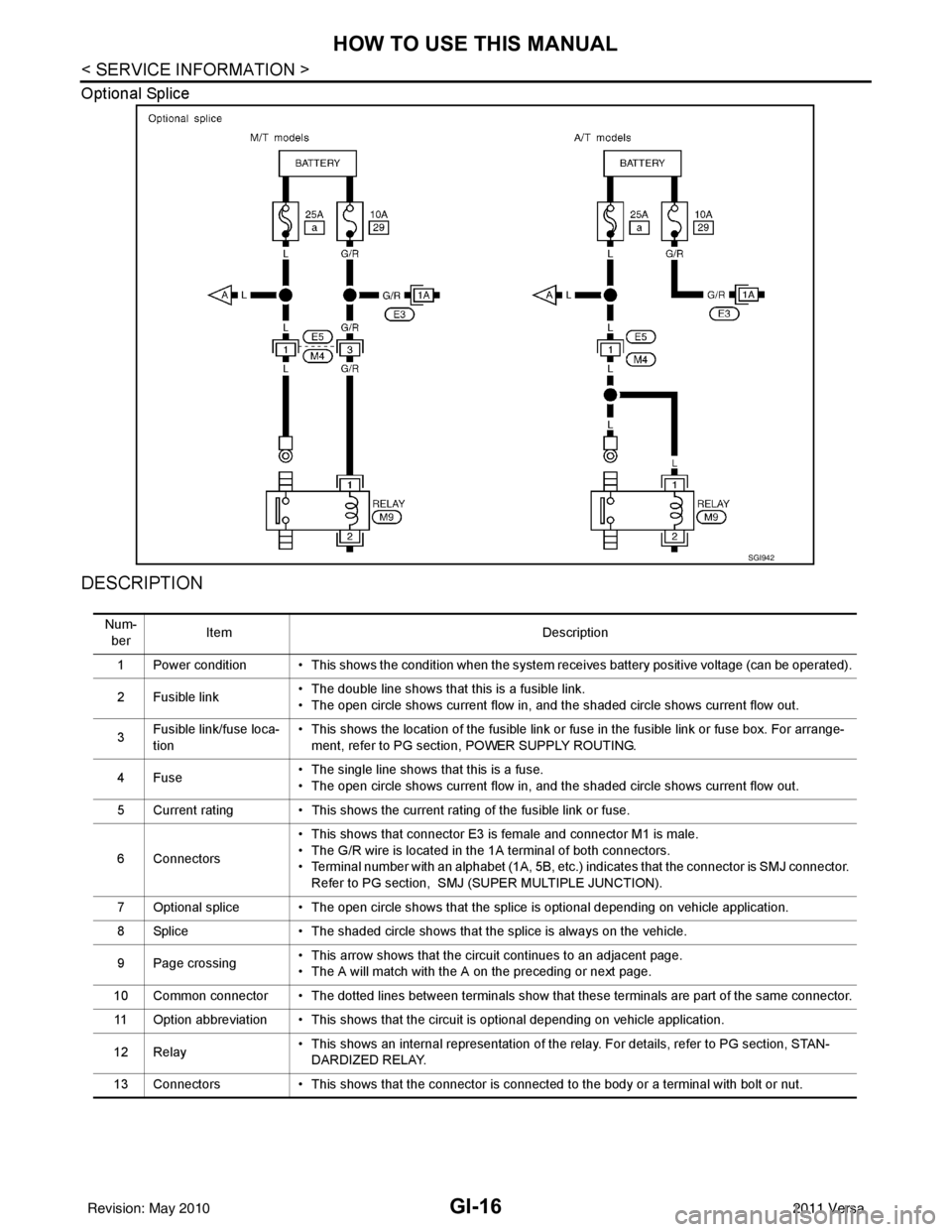
Optional Splice
DESCRIPTION
SGI942
Num-ber Item
Description
1 Power condition • This shows the condition when the system receives battery positive voltage (can be operated).
2 Fusible link • The double line shows that this is a fusible link.
• The open circle shows current flow in, and the shaded circle shows current flow out.
3 Fusible link/fuse loca-
tion • This shows the location of the fusible link or fuse in the fusible link or fuse box. For arrange-
ment, refer to PG section, POWER SUPPLY ROUTING.
4Fuse • The single line shows that this is a fuse.
• The open circle shows current flow in, and the shaded circle shows current flow out.
5 Current rating • This shows the current rating of the fusible link or fuse.
6 Connectors • This shows that connector E3 is female and connector M1 is male.
• The G/R wire is located in the 1A terminal of both connectors.
• Terminal number with an alphabet (1A, 5B, etc.) indicates that the connector is SMJ connector.
Refer to PG section, SMJ (SUPER MULTIPLE JUNCTION).
7 Optional splice • The open circle shows that the splice is optional depending on vehicle application.
8 Splice • The shaded circle shows that the splice is always on the vehicle.
9 Page crossing • This arrow shows that the circuit continues to an adjacent page.
• The A will match with the A on the preceding or next page.
10 Common connector • The dotted lines between terminals show that these terminals are part of the same connector. 11 Option abbreviation • This shows that the circuit is optional depending on vehicle application.
12 Relay • This shows an internal representation of the relay. For details, refer to PG section, STAN-
DARDIZED RELAY.
13 Connectors • This shows that the connector is connected to the body or a terminal with bolt or nut.
Revision: May 2010 2011 Versa
Page 2773 of 3787
POWER WINDOW SYSTEMGW-19
< SERVICE INFORMATION >
C
DE
F
G H
J
K L
M A
B
GW
N
O P
POWER WINDOW SYSTEM
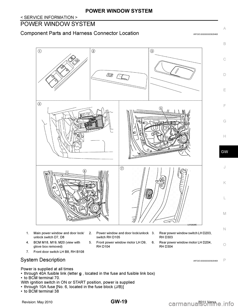
Component Parts and Har ness Connector LocationINFOID:0000000005929468
System DescriptionINFOID:0000000005929469
Power is supplied at all times
• through 40A fusible link (letter g , located in the fuse and fusible link box)
• to BCM terminal 70.
With ignition switch in ON or START position, power is supplied
• through 10A fuse [No. 6, located in the fuse block (J/B)]
• to BCM terminal 38
1. Main power window and door lock/
unlock switch D7, D8 2. Power window and door lock/unlock
switch RH D105 3. Rear power window switch LH D203,
RH D303
4. BCM M18, M19, M20 (view with glove box removed) 5. Front power window motor LH D9,
RH D104 6. Rear power window motor LH D204,
RH D304
7. Front door switch LH B8, RH B108
LIIA2529E
Revision: May 2010 2011 Versa
Page 3037 of 3787
HEADLAMP (FOR USA)LT-5
< SERVICE INFORMATION >
C
DE
F
G H
I
J
L
M A
B
LT
N
O P
HEADLAMP (FOR USA)
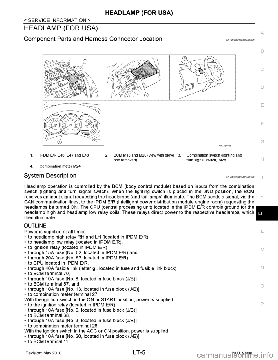
Component Parts and Har ness Connector LocationINFOID:0000000005929028
System DescriptionINFOID:0000000005929029
Headlamp operation is controlled by the BCM (body c ontrol module) based on inputs from the combination
switch (lighting and turn signal switch). When the light ing switch is placed in the 2ND position, the BCM
receives an input signal requesting the headlamps (and tail lamps) illuminate. The BCM sends a signal, via the
CAN communication lines, to the IPDM E/R (intelligent power distribution module engine room) requesting the
headlamps be turned ON. The CPU (centra l processing unit) located in the IPDM E/R controls ground for the
headlamp high and headlamp low relay coils. These relays direct power to the respective headlamps, which
then illuminate.
OUTLINE
Power is supplied at all times
• to headlamp high relay RH and LH (located in IPDM E/R),
• to headlamp low relay (located in IPDM E/R),
• to ignition relay (located in IPDM E/R),
• through 15A fuse (No. 52, located in IPDM E/R) and
• through 20A fuse (No. 53, located in IPDM E/R)
• to CPU located in IPDM E/R,
• through 40A fusible link (letter g , located in fuse and fusible link block)
• to BCM terminal 70,
• through 10A fuse [No. 8, located in fuse block (J/B)]
• to BCM terminal 57, and
• through 10A fuse [No. 13, located in fuse block (J/B)]
• to combination meter terminal 27.
With the ignition switch in the ON or START position, power is supplied
• to the ignition relay (located in IPDM E/R),
• through 10A fuse [No. 6, located in fuse block (J/B)]
• to BCM terminal 38,
• through 10A fuse [No. 3, located in fuse block (J/B)]
• to combination meter terminal 28.
With the ignition switch in the ACC or ON position, power is supplied
• through 10A fuse [No. 20, located in fuse block (J/B)]
• to BCM terminal 11.
1. IPDM E/R E46, E47 and E48 2. BCM M18 and M20 (view with glove
box removed)3. Combination switch (lighting and
turn signal switch) M28
4. Combination meter M24
WKIA5469E
Revision: May 2010 2011 Versa