2011 NISSAN TIIDA evaporator
[x] Cancel search: evaporatorPage 3318 of 3787

MTC-2
REFRIGERANT LINES ......................................74
HFC-134a (R-134a) Service Procedure .............. ...74
Component .............................................................76
Removal and Installation of Compressor -
HR16DE .................................................................
78
Removal and Installation of Compressor -
MR18DE .................................................................
80
Removal and Installation for Compressor Clutch -
Type 1 .................................................................. ...
81
Removal and Installation for Compressor Clutch -
Type 2 .................................................................. ...
83
Removal and Installation of Low-Pressure Flexi-
ble Hose .................................................................
86
Removal and Installation of High-Pressure Flexi-
ble Hose .................................................................
87
Removal and Installation of High-Pressure Pipe ....88
Removal and Installation of Refrigerant Pressure
Sensor .................................................................. ...
89
Removal and Installation of Condenser ..................89
Removal and Installation of Liquid Tank .................90
Removal and Installation of Evaporator ............... ...91
Removal and Installation of Expansion Valve .........92
Checking of Refrigerant Leaks ................................92
Checking System for Leaks Using the Fluorescent
Leak Detector ..........................................................
92
Dye Injection ...........................................................93
Electronic Refrigerant Leak Detector ......................93
SERVICE DATA AND SPECIFICATIONS
(SDS) .................................................................
96
Compressor ......................................................... ...96
Oil ............................................................................96
Refrigerant ..............................................................96
Revision: May 2010 2011 Versa
Page 3321 of 3787
PRECAUTIONSMTC-5
< SERVICE INFORMATION >
C
DE
F
G H
I
K L
M A
B
MTC
N
O P
been shown to be combustible at elevated pressures. These mixtures, if ignited, may cause injury or
property damage. Additional health and safety info rmation may be obtained from refrigerant manu-
facturers.
Oil PrecautionINFOID:0000000005930828
• Use only specified oil for the HFC-134a (R-134a) A/C system and HFC-134a (R-134a) components. If oil
other than that specified is used, comp ressor malfunction is likely to occur.
• The specified HFC-134a (R-134a) oil rapidly absorbs moisture from the atmosphere. The following handling
precautions must be observed:
- When removing refrigerant components from a vehicle, immediately cap (seal) the component to minimize the entry of moisture from the atmosphere.
- When installing refrigerant components to a vehicle, do not remove the caps (unseal) until just before con- necting the components. Connect all refrigerant loop components as quickly as possible to minimize the
entry of moisture into system.
- Only use the specified oil from a sealed container. Imm ediately reseal containers of oil. Without proper seal-
ing, oil will become moisture saturated and should not be used.
• Avoid breathing A/C refrigerant and oil vapor or mist. Exposure may irritate eyes, nose and throat.
Use only approved recovery/recycling equipment to discharge HFC-134a (R-134a) refrigerant. If accidental
system discharge occurs, ventilate work area before resuming service. Additional health and safety informa-
tion may be obtained from refrigerant and oil manufacturers.
• Do not allow A/C oil to come in contact with styrofoam parts. Damage may result.
Precaution for Refrigerant ConnectionINFOID:0000000005930829
A new type refrigerant connection has been introduced to a ll refrigerant lines except the following location.
• Expansion valve to evaporator
• Refrigerant pressure sensor to condenser
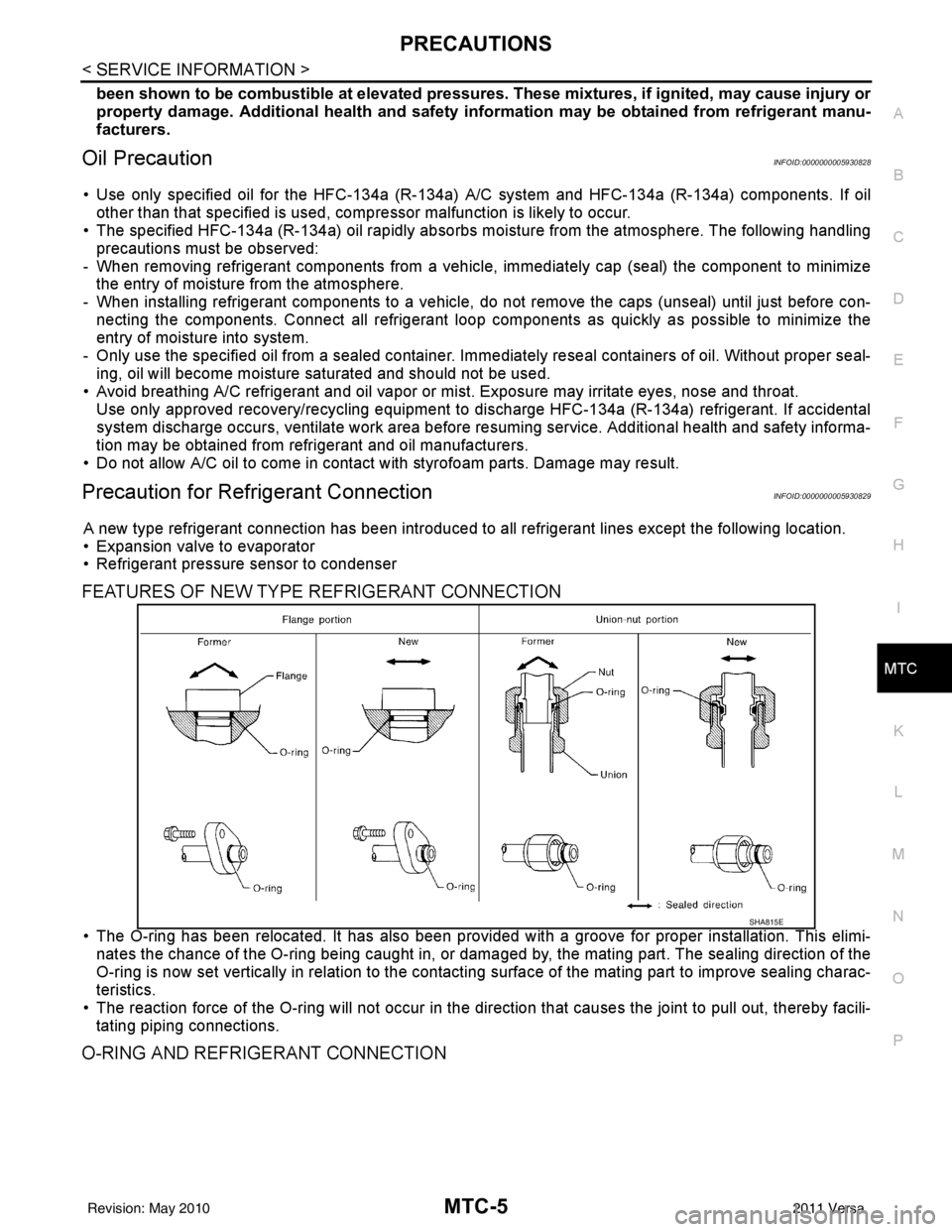
FEATURES OF NEW TYPE REFRIGERANT CONNECTION
• The O-ring has been relocated. It has also been provided with a groove for proper installation. This elimi-
nates the chance of the O-ring being caught in, or damaged by, the mating part. The sealing direction of the
O-ring is now set vertically in relation to the contacti ng surface of the mating part to improve sealing charac-
teristics.
• The reaction force of the O-ring will not occur in the direction that causes the joint to pull out, thereby facili- tating piping connections.
O-RING AND REFRIGERANT CONNECTION
SHA815E
Revision: May 2010 2011 Versa
Page 3323 of 3787
PRECAUTIONSMTC-7
< SERVICE INFORMATION >
C
DE
F
G H
I
K L
M A
B
MTC
N
O P
O-Ring Specifications*
* : Always check with the parts department for the latest parts information.
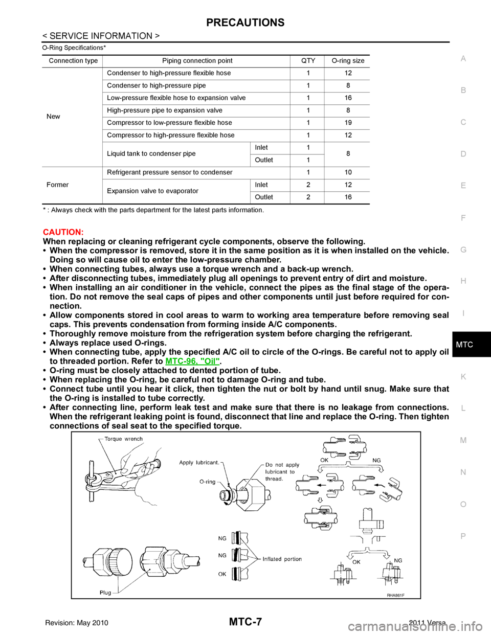
CAUTION:
When replacing or cleaning refrigerant cycle components, observe the following.
• When the compressor is removed, store it in the sam e position as it is when installed on the vehicle.
Doing so will cause oil to en ter the low-pressure chamber.
• When connecting tubes, always use a to rque wrench and a back-up wrench.
• After disconnecting tubes, immediately plug all op enings to prevent entry of dirt and moisture.
• When installing an air conditione r in the vehicle, connect the pipes as the final stage of the opera-
tion. Do not remove the seal caps of pipes and other components until just before required for con-
nection.
• Allow components stored in cool areas to warm to working area temperature before removing seal
caps. This prevents condensation from forming inside A/C components.
• Thoroughly remove moisture from the refrigeration system before charging the refrigerant.
• Always replace used O-rings.
• When connecting tube, apply the speci fied A/C oil to circle of the O-rings. Be careful not to apply oil
to threaded portion. Refer to MTC-96, "
Oil".
• O-ring must be closely attached to dented portion of tube.
• When replacing the O-ring, be careful not to damage O-ring and tube.
• Connect tube until you hear it cl ick, then tighten the nut or bolt by hand until snug. Make sure that
the O-ring is installed to tube correctly.
• After connecting line, perform leak test and make sure that there is no leakage from connections.
When the refrigerant leaking point is found, disconnect that line and replace the O-ring. Then tighten
connections of seal seat to the specified torque.
Connection type Piping connection point QTY O-ring size
New Condenser to high-pressure flexible hose
112
Condenser to high-pressure pipe 18
Low-pressure flexible hose to expansion valve 116
High-pressure pipe to expansion valve 18
Compressor to low-pressure flexible hose 119
Compressor to high-pressure flexible hose 112
Liquid tank to condenser pipe Inlet
1
8
Outlet 1
Former Refrigerant pressure sensor to condenser
110
Expansion valve to evaporator Inlet
212
Outlet 2 16
RHA861F
Revision: May 2010 2011 Versa
Page 3331 of 3787
REFRIGERATION SYSTEMMTC-15
< SERVICE INFORMATION >
C
DE
F
G H
I
K L
M A
B
MTC
N
O P
REFRIGERATION SYSTEM
Refrigerant CycleINFOID:0000000005930835
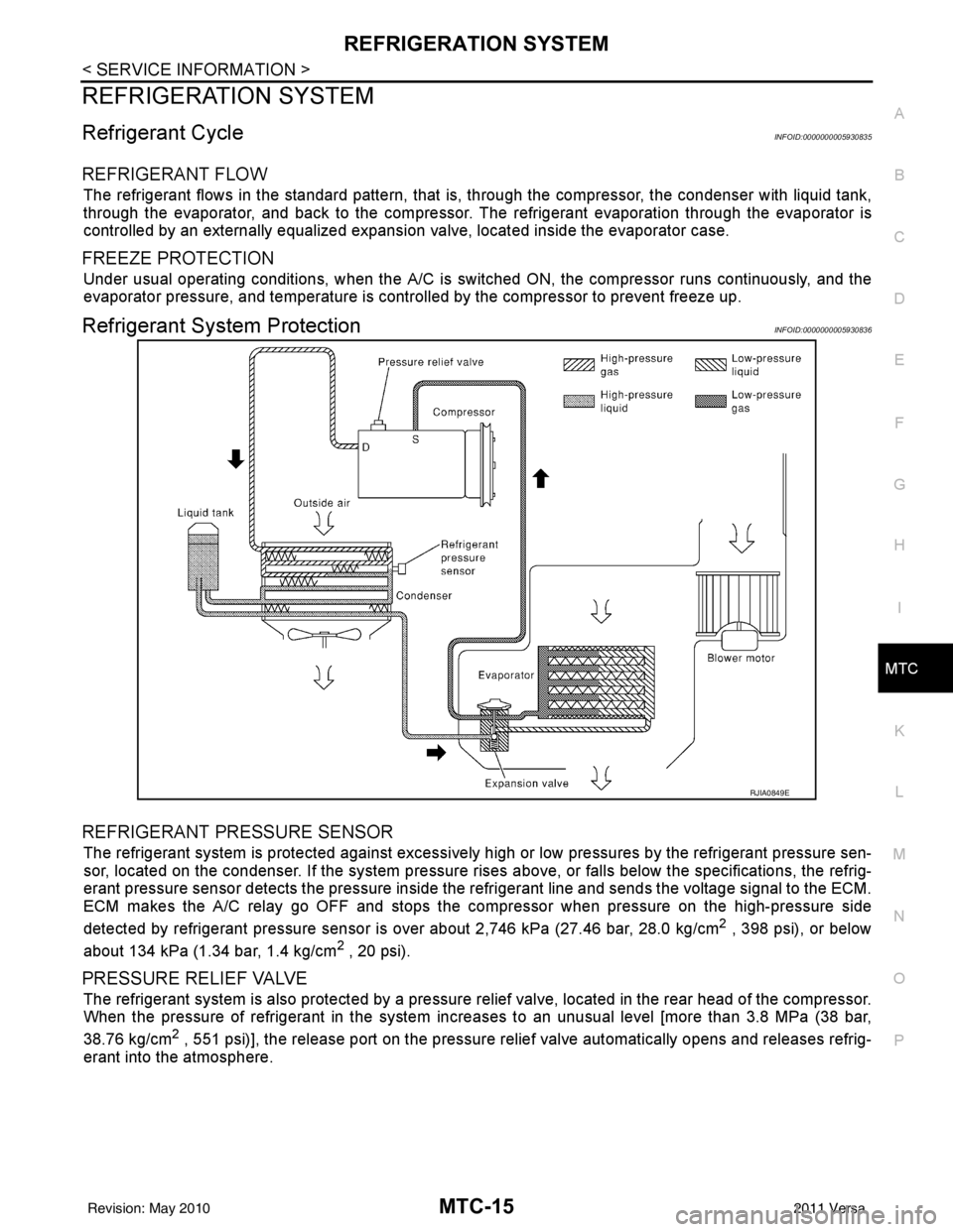
REFRIGERANT FLOW
The refrigerant flows in the standard pattern, that is, through the compressor, the condenser with liquid tank,
through the evaporator, and back to the compressor. T he refrigerant evaporation through the evaporator is
controlled by an externally equalized expansion valve, located inside the evaporator case.
FREEZE PROTECTION
Under usual operating conditions, when the A/C is s witched ON, the compressor runs continuously, and the
evaporator pressure, and temperature is controlled by the compressor to prevent freeze up.
Refrigerant System ProtectionINFOID:0000000005930836
REFRIGERANT PRESSURE SENSOR
The refrigerant system is protected against excessively hi gh or low pressures by the refrigerant pressure sen-
sor, located on the condenser. If the system pressure rises above, or falls below the specifications, the refrig-
erant pressure sensor detects the pressure inside t he refrigerant line and sends the voltage signal to the ECM.
ECM makes the A/C relay go OFF and stops the compressor when pressure on the high-pressure side
detected by refrigerant pressure sensor is over about 2,746 kPa (27.46 bar, 28.0 kg/cm
2 , 398 psi), or below
about 134 kPa (1.34 bar, 1.4 kg/cm
2 , 20 psi).
PRESSURE RELIEF VALVE
The refrigerant system is also protected by a pressure relief valve, located in the rear head of the compressor.
When the pressure of refrigerant in the system in creases to an unusual level [more than 3.8 MPa (38 bar,
38.76 kg/cm
2 , 551 psi)], the release port on the pressure relief valve automatically opens and releases refrig-
erant into the atmosphere.
RJIA0849E
Revision: May 2010 2011 Versa
Page 3333 of 3787
OIL
MTC-17
< SERVICE INFORMATION >
C
D E
F
G H
I
K L
M A
B
MTC
N
O P
OIL
Maintenance of Oil Qu antity in CompressorINFOID:0000000005930838
The oil in the compressor circulates through the system with the refrigerant. Add oil to compressor when
replacing any component or after a large refrigerant leakage occurred. It is important to maintain the specified
amount.
If oil quantity is not maintained properly , the following malfunctions may result:
• Lack of oil: May lead to a seized compressor.
• Excessive oil: Inadequate cooling (thermal exchange interference)
OIL
OIL ADJUSTING PROCEDURE FOR COMPONENTS REPLACEMENT EXCEPT COMPRESSOR
After replacing any of the following major components, add the correct amount of oil to the system.
Amount Of Oil To Be Added
*1: If refrigerant leak is small, no addition of oil is needed.
OIL ADJUSTING PROCEDURE FOR COMPRESSOR REPLACEMENT
TYPE 1 Compressor (CR-10) : NISSAN A/C System Oil Type R
TYPE 2 Compressor (CSV511) : NISSAN A/C System Oil Type S
Part replaced Oil to be added to system
Remarks
Amount of oil
m (US fl oz, Imp fl oz)
Evaporator 35 (1.2, 1.2)-
Condenser 15 (0.5, 0.5)-
Liquid tank 5 (0.2, 0.2)-
In case of refrigerant leak 30 (1.0, 1.1)
Large leak
None *1 Small leak
*1
Revision: May 2010 2011 Versa
Page 3362 of 3787
MTC-46
< SERVICE INFORMATION >
TROUBLE DIAGNOSIS
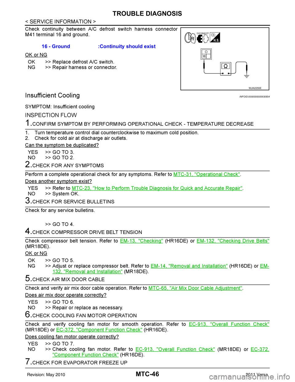
Check continuity between A/C defrost switch harness connector
M41 terminal 16 and ground.
OK or NG
OK >> Replace defrost A/C switch.
NG >> Repair harness or connector.
Insufficient CoolingINFOID:0000000005930854
SYMPTOM: Insufficient cooling
INSPECTION FLOW
1.CONFIRM SYMPTOM BY PERFORMING OPERATIONAL CHECK - TEMPERATURE DECREASE
1. Turn temperature control dial counterclockwise to maximum cold position.
2. Check for cold air at discharge air outlets.
Can the symptom be duplicated?
YES >> GO TO 3.
NO >> GO TO 2.
2.CHECK FOR ANY SYMPTOMS
Perform a complete operational check for any symptoms. Refer to MTC-31, "
Operational Check".
Does another symptom exist?
YES >> Refer to MTC-23, "How to Perform Trouble Diagnosis for Quick and Accurate Repair".
NO >> System OK.
3.CHECK FOR SERVICE BULLETINS
Check for any service bulletins.
>> GO TO 4.
4.CHECK COMPRESSOR DRIVE BELT TENSION
Check compressor belt tension. Refer to EM-13, "
Checking" (HR16DE) or EM-132, "Checking Drive Belts"
(MR18DE).
OK or NG
OK >> GO TO 5.
NG >> Adjust or replace compressor belt. Refer to EM-14, "
Removal and Installation" (HR16DE) or EM-
132, "Removal and Installation" (MR18DE).
5.CHECK AIR MIX DOOR CABLE
Check and verify air mix door cable operation. Refer to MTC-65, "
Air Mix Door Cable Adjustment".
Does air mix door operate correctly?
YES >> GO TO 6.
NO >> Repair or replace as necessary.
6.CHECK COOLING FAN MOTOR OPERATION
Check and verify cooling fan motor for smooth operation. Refer to EC-913, "
Overall Function Check"
(MR18DE) or EC-372, "Component Function Check" (HR16DE).
Does cooling fan motor operate correctly?
YES >> GO TO 7.
NO >> Check cooling fan motor. Refer to EC-913, "
Overall Function Check" (MR18DE) or EC-372,
"Component Function Check" (HR16DE).
7.CHECK FOR EVAPORATOR FREEZE UP16 - Ground :Continuity should exist
WJIA2255E
Revision: May 2010
2011 Versa
Page 3363 of 3787
TROUBLE DIAGNOSISMTC-47
< SERVICE INFORMATION >
C
DE
F
G H
I
K L
M A
B
MTC
N
O P
Start engine and run A/C. Check for evaporator freeze up.
Does evaporator freeze up?
YES >> Perform diagnostic work flow. Refer to "DIAGNOSTIC WORK FLOW".
NO >> GO TO 8.
8.CHECK REFRIGERANT PRESSURE
Check refrigerant pressure with manifold gauge connected. Refer to "PERFORMANCE CHART".
OK or NG
OK >> GO TO 9.
NG >> Perform diagnostic work flow. Refer to "DIAGNOSTIC WORK FLOW".
9.CHECK AIR DUCTS
Check ducts for air leaks.
OK or NG
OK >> If the symptom still exists, perform a complete operational check. Refer to MTC-31, "Operational
Check". If other symptoms exist, refer to MTC-23, "How to Perform Trouble Diagnosis for Quick
and Accurate Repair".
NG >> Repair air leaks.
DIAGNOSTIC WORK FLOW
Revision: May 2010 2011 Versa
Page 3367 of 3787
TROUBLE DIAGNOSISMTC-51
< SERVICE INFORMATION >
C
DE
F
G H
I
K L
M A
B
MTC
N
O P
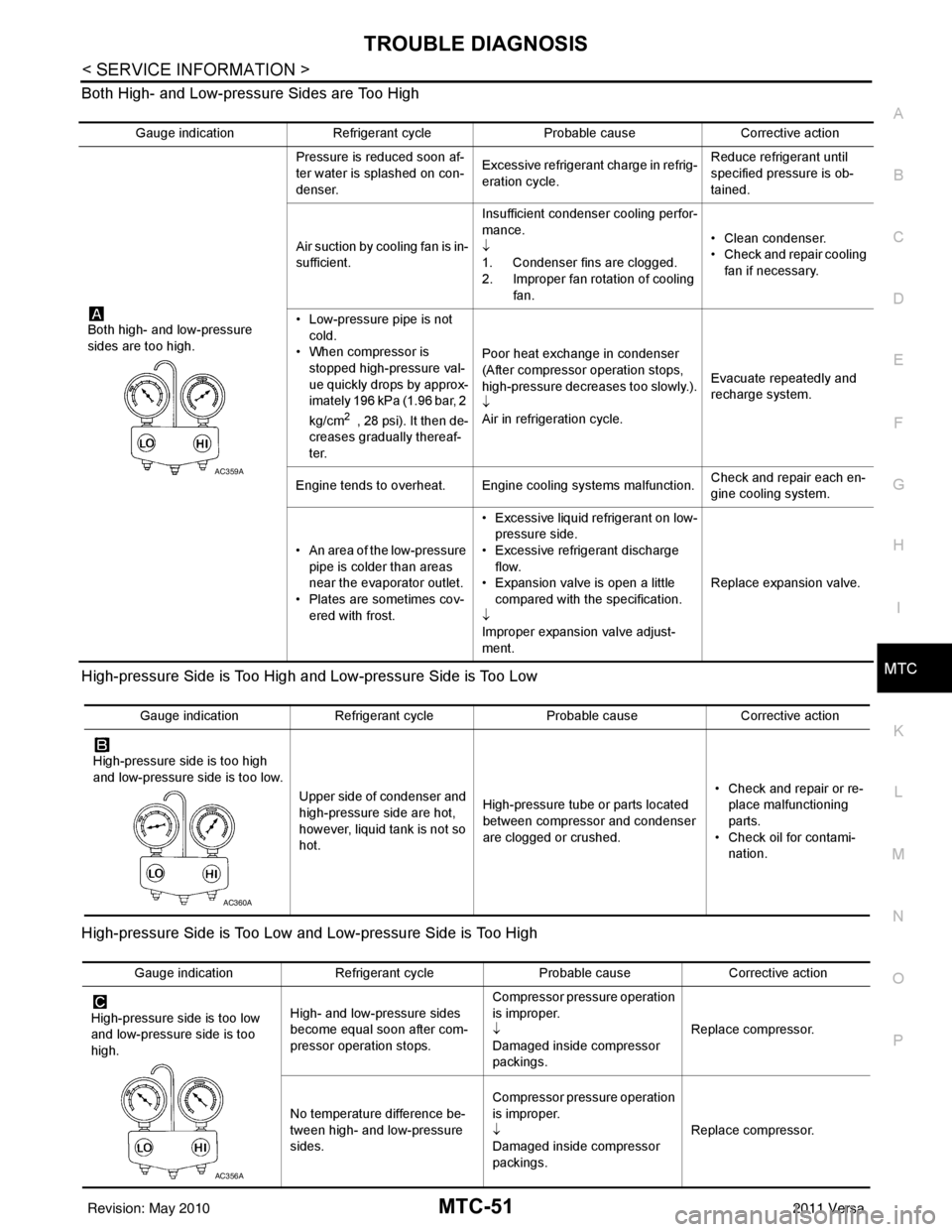
Both High- and Low-pressure Sides are Too High
High-pressure Side is Too High and Low-pressure Side is Too Low
High-pressure Side is Too Low and Low-pressure Side is Too High
Gauge indication
Refrigerant cycle Probable causeCorrective action
Both high- and low-pressure
sides are too high. Pressure is reduced soon af-
ter water is splashed on con-
denser.
Excessive refrigerant charge in refrig-
eration cycle. Reduce refrigerant until
specified pressure is ob-
tained.
Air suction by cooling fan is in-
sufficient. Insufficient condenser cooling perfor-
mance.
↓
1. Condenser fins are clogged.
2. Improper fan rotation of cooling
fan. • Clean condenser.
• Check and repair cooling
fan if necessary.
• Low-pressure pipe is not cold.
• When compressor is
stopped high-pressure val-
ue quickly drops by approx-
imately 196 kPa (1.96 bar, 2
kg/cm
2 , 28 psi). It then de-
creases gradually thereaf-
ter. Poor heat exchange in condenser
(After compressor operation stops,
high-pressure decreases too slowly.).
↓
Air in refrigeration cycle.
Evacuate repeatedly and
recharge system.
Engine tends to overheat. Engine cooling systems malfunction. Check and repair each en-
gine cooling system.
• An area of the low-pressure pipe is colder than areas
near the evaporator outlet.
• Plates are sometimes cov- ered with frost. • Excessive liquid refrigerant on low-
pressure side.
• Excessive refrigerant discharge flow.
• Expansion valve is open a little
compared with the specification.
↓
Improper expansion valve adjust-
ment. Replace expansion valve.
AC359A
Gauge indication
Refrigerant cycle Probable causeCorrective action
High-pressure side is too high
and low-pressure side is too low. Upper side of condenser and
high-pressure side are hot,
however, liquid tank is not so
hot.High-pressure tube or parts located
between compressor and condenser
are clogged or crushed. • Check and repair or re-
place malfunctioning
parts.
• Check oil for contami- nation.
AC360A
Gauge indication Refrigerant cycle Probable causeCorrective action
High-pressure side is too low
and low-pressure side is too
high. High- and low-pressure sides
become equal soon after com-
pressor operation stops. Compressor pressure operation
is improper.
↓
Damaged inside compressor
packings.
Replace compressor.
No temperature difference be-
tween high- and low-pressure
sides. Compressor pressure operation
is improper.
↓
Damaged inside compressor
packings.
Replace compressor.
AC356A
Revision: May 2010
2011 Versa