2011 NISSAN TIIDA Block
[x] Cancel search: BlockPage 68 of 3787
TROUBLE DIAGNOSISAT-51
< SERVICE INFORMATION >
DE
F
G H
I
J
K L
M A
B
AT
N
O P
Inspections Before Trouble DiagnosisINFOID:0000000005928094
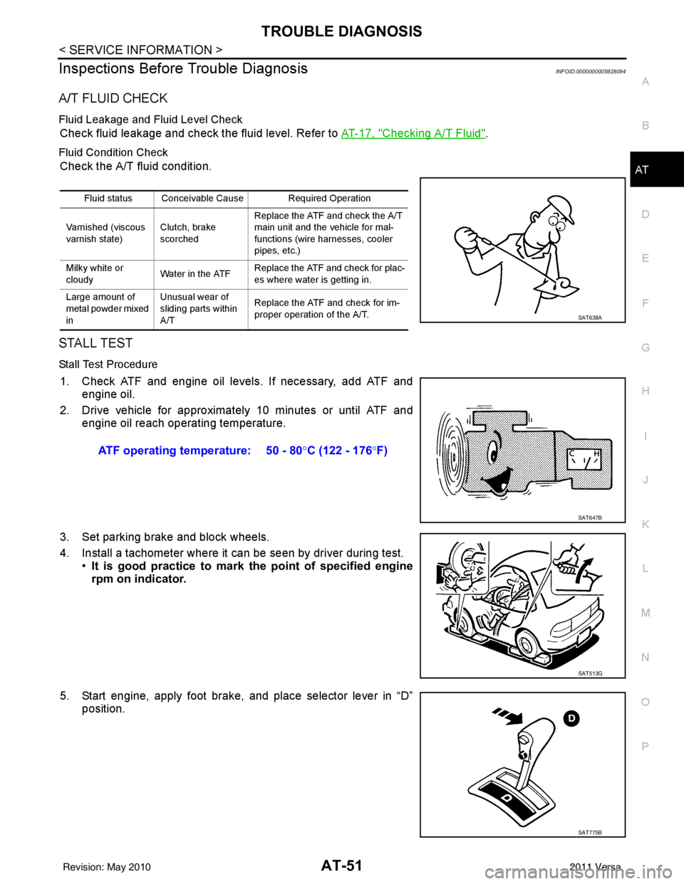
A/T FLUID CHECK
Fluid Leakage and Fluid Level Check
Check fluid leakage and check the fluid level. Refer to AT-17, "Checking A/T Fluid".
Fluid Condition Check
Check the A/T fluid condition.
STALL TEST
Stall Test Procedure
1. Check ATF and engine oil levels. If necessary, add ATF and engine oil.
2. Drive vehicle for approximately 10 minutes or until ATF and engine oil reach operating temperature.
3. Set parking brake and block wheels.
4. Install a tachometer where it can be seen by driver during test. •It is good practice to mark the point of specified engine
rpm on indicator.
5. Start engine, apply foot brake, and place selector lever in “D” position.
Fluid status Conceivable Cause Required Operation
Varnished (viscous
varnish state) Clutch, brake
scorchedReplace the ATF and check the A/T
main unit and the vehicle for mal-
functions (wire harnesses, cooler
pipes, etc.)
Milky white or
cloudy Water in the ATFReplace the ATF and check for plac-
es where water is getting in.
Large amount of
metal powder mixed
in Unusual wear of
sliding parts within
A/T
Replace the ATF and check for im-
proper operation of the A/T.
SAT638A
ATF operating temperature: 50 - 80
°C (122 - 176 °F)
SAT647B
SAT513G
SAT775B
Revision: May 2010 2011 Versa
Page 71 of 3787
AT-54
< SERVICE INFORMATION >
TROUBLE DIAGNOSIS
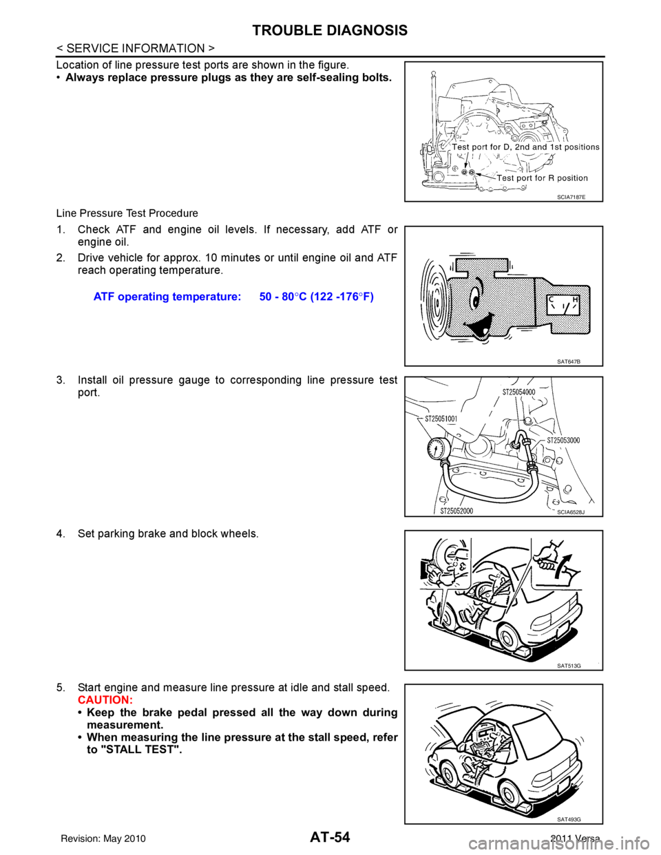
Location of line pressure test ports are shown in the figure.
•Always replace pressure plugs as they are self-sealing bolts.
Line Pressure Test Procedure
1. Check ATF and engine oil levels. If necessary, add ATF or
engine oil.
2. Drive vehicle for approx. 10 minutes or until engine oil and ATF reach operating temperature.
3. Install oil pressure gauge to corresponding line pressure test port.
4. Set parking brake and block wheels.
5. Start engine and measure line pressure at idle and stall speed. CAUTION:
• Keep the brake pedal pressed all the way down duringmeasurement.
• When measuring the line pressure at the stall speed, refer to "STALL TEST".
SCIA7187E
ATF operating temperature: 50 - 80° C (122 -176°F)
SAT647B
SCIA6528J
SAT513G
SAT493G
Revision: May 2010 2011 Versa
Page 175 of 3787
AT-158
< SERVICE INFORMATION >
BATT/FLUID TEMP SEN
Diagnosis Procedure
INFOID:0000000005928223
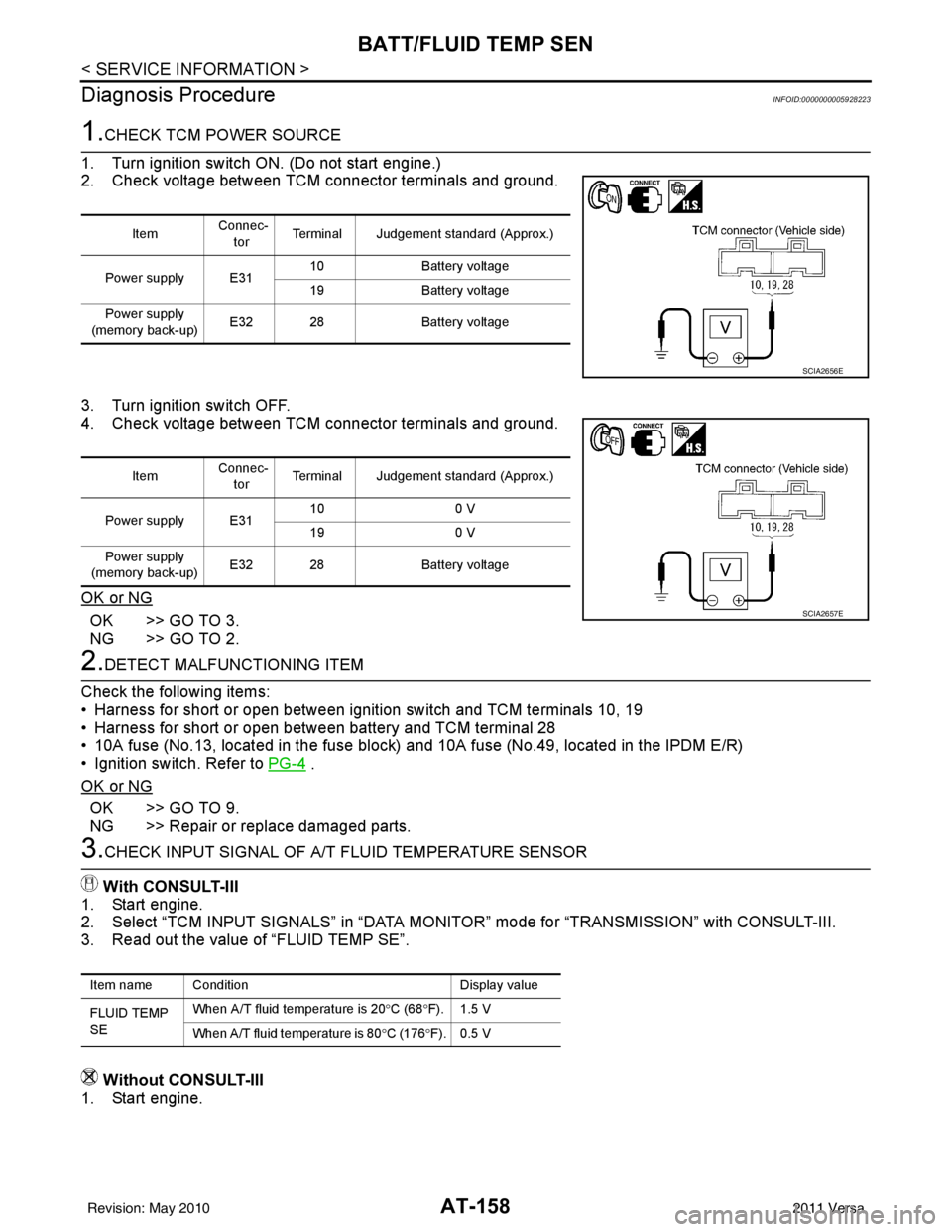
1.CHECK TCM POWER SOURCE
1. Turn ignition switch ON. (Do not start engine.)
2. Check voltage between TCM connector terminals and ground.
3. Turn ignition switch OFF.
4. Check voltage between TCM connector terminals and ground.
OK or NG
OK >> GO TO 3.
NG >> GO TO 2.
2.DETECT MALFUNCTIONING ITEM
Check the following items:
• Harness for short or open between ignition switch and TCM terminals 10, 19
• Harness for short or open between battery and TCM terminal 28
• 10A fuse (No.13, located in the fuse block) and 10A fuse (No.49, located in the IPDM E/R)
• Ignition switch. Refer to PG-4
.
OK or NG
OK >> GO TO 9.
NG >> Repair or replace damaged parts.
3.CHECK INPUT SIGNAL OF A/ T FLUID TEMPERATURE SENSOR
With CONSULT-III
1. Start engine.
2. Select “TCM INPUT SIGNALS” in “DATA MONITOR” mode for “TRANSMISSION” with CONSULT-III.
3. Read out the value of “FLUID TEMP SE”.
Without CONSULT-III
1. Start engine.
Item Connec-
tor Terminal Judgement standard (Approx.)
Power supply E31 10
Battery voltage
19 Battery voltage
Power supply
(memory back-up) E32 28
Battery voltage
SCIA2656E
Item Connec-
tor Terminal Judgement standard (Approx.)
Power supply E31 10
0 V
19 0 V
Power supply
(memory back-up) E32 28
Battery voltage
SCIA2657E
Item name Condition Display value
FLUID TEMP
SE When A/T fluid temperature is 20
°C (68 °F). 1.5 V
When A/T fluid temperature is 80 °C (176 °F). 0.5 V
Revision: May 2010 2011 Versa
Page 186 of 3787
MAIN POWER SUPPLY AND GROUND CIRCUITAT-169
< SERVICE INFORMATION >
DE
F
G H
I
J
K L
M A
B
AT
N
O P
Diagnosis ProcedureINFOID:0000000005928238
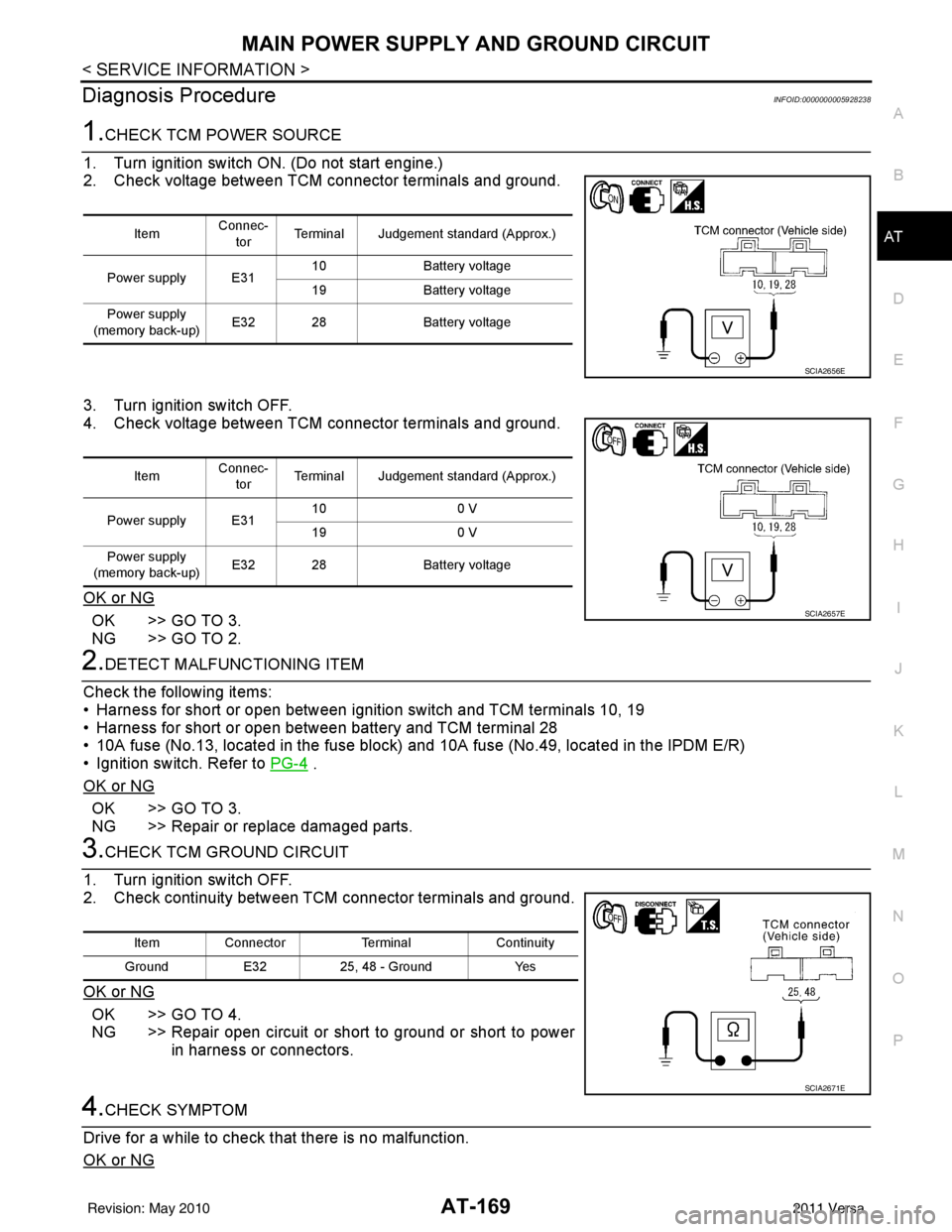
1.CHECK TCM POWER SOURCE
1. Turn ignition switch ON. (Do not start engine.)
2. Check voltage between TCM connector terminals and ground.
3. Turn ignition switch OFF.
4. Check voltage between TCM connector terminals and ground.
OK or NG
OK >> GO TO 3.
NG >> GO TO 2.
2.DETECT MALFUNCTIONING ITEM
Check the following items:
• Harness for short or open between ignition switch and TCM terminals 10, 19
• Harness for short or open between battery and TCM terminal 28
• 10A fuse (No.13, located in the fuse block) and 10A fuse (No.49, located in the IPDM E/R)
• Ignition switch. Refer to PG-4
.
OK or NG
OK >> GO TO 3.
NG >> Repair or replace damaged parts.
3.CHECK TCM GROUND CIRCUIT
1. Turn ignition switch OFF.
2. Check continuity between TCM connector terminals and ground.
OK or NG
OK >> GO TO 4.
NG >> Repair open circuit or short to ground or short to power in harness or connectors.
4.CHECK SYMPTOM
Drive for a while to check that there is no malfunction.
OK or NG
Item Connec-
tor Terminal Judgement standard (Approx.)
Power supply E31 10
Battery voltage
19 Battery voltage
Power supply
(memory back-up) E32 28
Battery voltage
SCIA2656E
ItemConnec-
tor Terminal Judgement standard (Approx.)
Power supply E31 10
0 V
19 0 V
Power supply
(memory back-up) E32 28
Battery voltage
SCIA2657E
Item Connector TerminalContinuity
Ground E3225, 48 - Ground Yes
SCIA2671E
Revision: May 2010 2011 Versa
Page 198 of 3787
TROUBLE DIAGNOSIS FOR SYMPTOMSAT-181
< SERVICE INFORMATION >
DE
F
G H
I
J
K L
M A
B
AT
N
O P
OD OFF indicator lamp does not come on for abou t 2 seconds when turning ignition switch to ON.
DIAGNOSTIC PROCEDURE
1.CHECK CAN COMMUNICATION LINE
Perform self-diagnosis. Refer to AT-77, "
CONSULT-III Function (TRANSMISSION)" .
Is a malfunction in CAN communication indicated in the results?
YES >> Check CAN communication line. Refer to AT- 8 7 .
NO >> GO TO 2.
2.CHECK TCM POWER SOURCE
1. Turn ignition switch ON. (Do not start engine.)
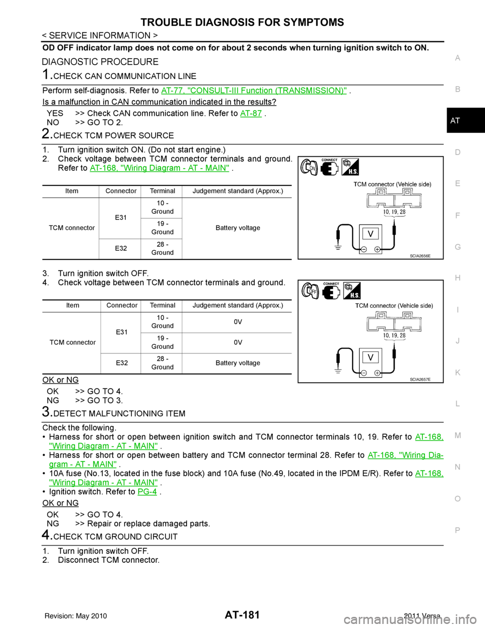
2. Check voltage between TCM connector terminals and ground. Refer to AT-168, "
Wiring Diagram - AT - MAIN" .
3. Turn ignition switch OFF.
4. Check voltage between TCM connector terminals and ground.
OK or NG
OK >> GO TO 4.
NG >> GO TO 3.
3.DETECT MALFUNCTIONING ITEM
Check the following.
• Harness for short or open between ignition switch and TCM connector terminals 10, 19. Refer to AT-168,
"Wiring Diagram - AT - MAIN" .
• Harness for short or open between battery and TCM connector terminal 28. Refer to AT-168, "
Wiring Dia-
gram - AT - MAIN" .
• 10A fuse (No.13, located in the fuse block) and 10A fuse (No.49, located in the IPDM E/R). Refer to AT-168,
"Wiring Diagram - AT - MAIN" .
• Ignition switch. Refer to PG-4
.
OK or NG
OK >> GO TO 4.
NG >> Repair or replace damaged parts.
4.CHECK TCM GROUND CIRCUIT
1. Turn ignition switch OFF.
2. Disconnect TCM connector.
Item Connector Terminal Judgement standard (Approx.)
TCM connector E3110 -
Ground
Battery voltage
19 -
Ground
E32 28 -
Ground
SCIA2656E
Item Connector Terminal Judgement standard (Approx.)
TCM connector E3110 -
Ground 0V
19 -
Ground 0V
E32 28 -
Ground Battery voltage
SCIA2657E
Revision: May 2010
2011 Versa
Page 227 of 3787
AT-210
< SERVICE INFORMATION >
A/T SHIFT LOCK SYSTEM
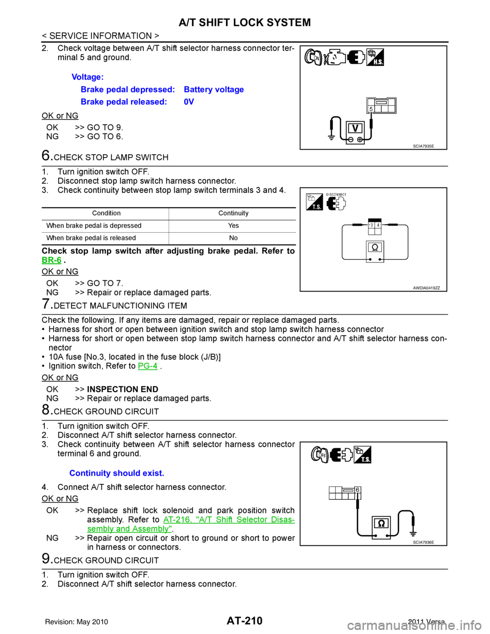
2. Check voltage between A/T shift selector harness connector ter-minal 5 and ground.
OK or NG
OK >> GO TO 9.
NG >> GO TO 6.
6.CHECK STOP LAMP SWITCH
1. Turn ignition switch OFF.
2. Disconnect stop lamp switch harness connector.
3. Check continuity between stop lamp switch terminals 3 and 4.
Check stop lamp switch after adjusting brake pedal. Refer to
BR-6
.
OK or NG
OK >> GO TO 7.
NG >> Repair or replace damaged parts.
7.DETECT MALFUNCTIONING ITEM
Check the following. If any items are damaged, repair or replace damaged parts.
• Harness for short or open between ignition switch and stop lamp switch harness connector
• Harness for short or open between stop lamp switch harness connector and A/T shift selector harness con-
nector
• 10A fuse [No.3, located in the fuse block (J/B)]
• Ignition switch, Refer to PG-4
.
OK or NG
OK >> INSPECTION END
NG >> Repair or replace damaged parts.
8.CHECK GROUND CIRCUIT
1. Turn ignition switch OFF.
2. Disconnect A/T shift selector harness connector.
3. Check continuity between A/T shift selector harness connector terminal 6 and ground.
4. Connect A/T shift selector harness connector.
OK or NG
OK >> Replace shift lock solenoid and park position switch assembly. Refer to AT-216, "
A/T Shift Selector Disas-
sembly and Assembly".
NG >> Repair open circuit or short to ground or short to power in harness or connectors.
9.CHECK GROUND CIRCUIT
1. Turn ignition switch OFF.
2. Disconnect A/T shift selector harness connector. Voltage:
Brake pedal depressed: Battery voltage
Brake pedal released: 0V
SCIA7935E
Condition Continuity
When brake pedal is depressed Yes
When brake pedal is released No
AWDIA0419ZZ
Continuity should exist.
SCIA7936E
Revision: May 2010 2011 Versa
Page 319 of 3787
AT-302
< SERVICE INFORMATION >
REPAIR FOR COMPONENT PARTS
7. Measure clearance between retaining plate and snap ring usingfeeler gauge. If not within allowable limit, select proper retaining
plate. Refer to “Parts Information” for retaining plate selection.
8. Check operation of reverse clutch.
High ClutchINFOID:0000000005928296
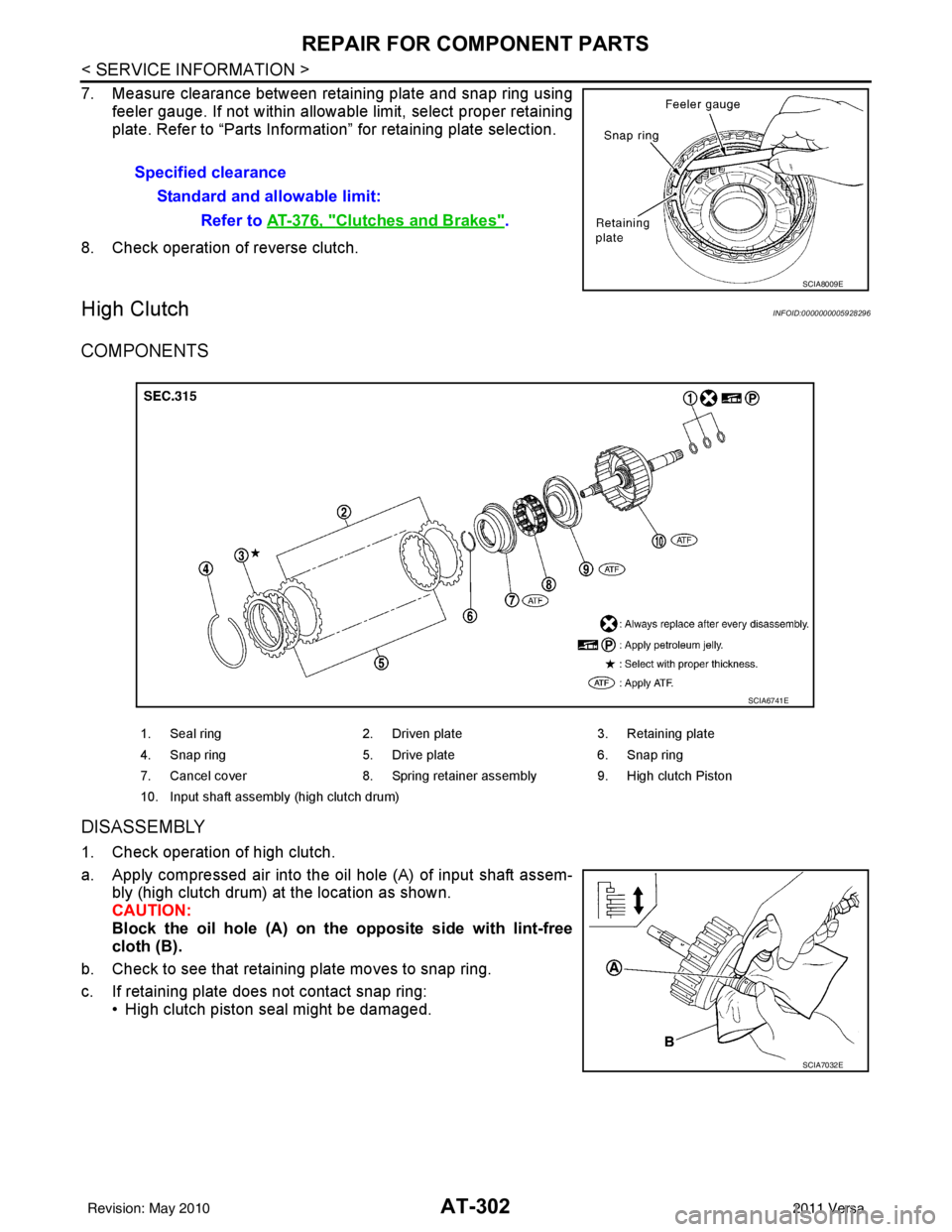
COMPONENTS
DISASSEMBLY
1. Check operation of high clutch.
a. Apply compressed air into the oil hole (A) of input shaft assem- bly (high clutch drum) at the location as shown.
CAUTION:
Block the oil hole (A) on the opposite side with lint-free
cloth (B).
b. Check to see that retaining plate moves to snap ring.
c. If retaining plate does not contact snap ring: • High clutch piston seal might be damaged.Specified clearance
Standard and allowable limit: Refer to AT-376, "
Clutches and Brakes".
SCIA8009E
1. Seal ring 2. Driven plate 3. Retaining plate
4. Snap ring 5. Drive plate 6. Snap ring
7. Cancel cover 8. Spring retainer assembly 9. High clutch Piston
10. Input shaft assembly (high clutch drum)
SCIA6741E
SCIA7032E
Revision: May 2010 2011 Versa
Page 320 of 3787
REPAIR FOR COMPONENT PARTSAT-303
< SERVICE INFORMATION >
DE
F
G H
I
J
K L
M A
B
AT
N
O P
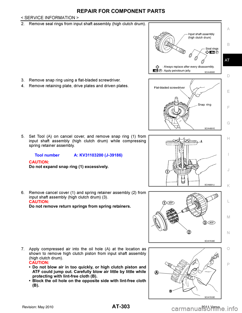
2. Remove seal rings from input shaft assembly (high clutch drum).
3. Remove snap ring using a flat-bladed screwdriver.
4. Remove retaining plate, drive plates and driven plates.
5. Set Tool (A) on cancel cover, and remove snap ring (1) from input shaft assembly (high clutch drum) while compressing
spring retainer assembly.
CAUTION:
Do not expand snap ring (1) excessively.
6. Remove cancel cover (1) and spring retainer assembly (2) from input shaft assembly (high clutch drum) (3).
CAUTION:
Do not remove return springs from spring retainers.
7. Apply compressed air into the oil hole (A) at the location as shown to remove high clutch piston from input shaft assembly
(high clutch drum).
CAUTION:
• Do not blow air in too quickly, or high clutch piston and
ATF could jump out. Carefully blow air little by little while
protecting with lint-free cloth (B).
• Block the oil hole on the oppo site side with lint-free cloth
(B).
SCIA4890E
SCIA4891E
Tool number A: KV31103200 (J-39186)
SCIA6001J
SCIA7036E
SCIA7033E
Revision: May 2010 2011 Versa