2011 NISSAN TIIDA Block
[x] Cancel search: BlockPage 350 of 3787
REPAIR FOR COMPONENT PARTSAT-333
< SERVICE INFORMATION >
DE
F
G H
I
J
K L
M A
B
AT
N
O P
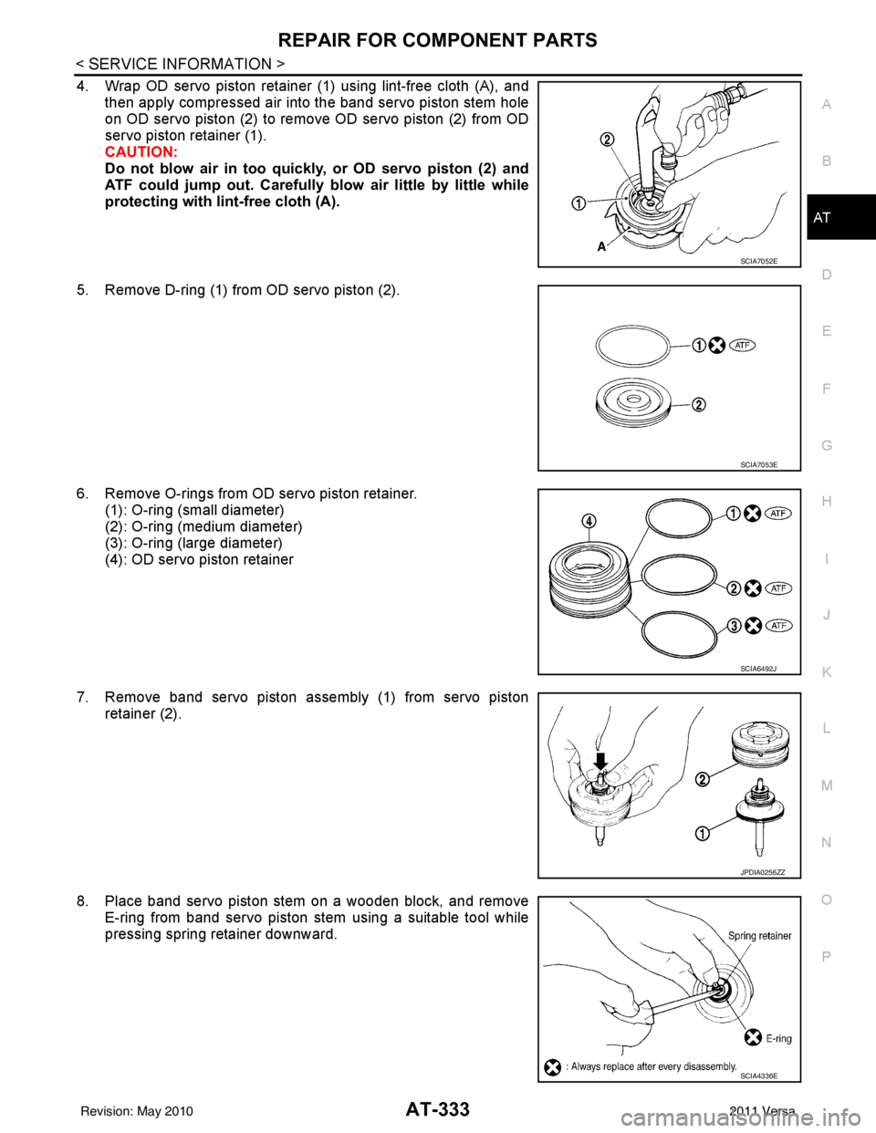
4. Wrap OD servo piston retainer (1) using lint-free cloth (A), and then apply compressed air into the band servo piston stem hole
on OD servo piston (2) to remove OD servo piston (2) from OD
servo piston retainer (1).
CAUTION:
Do not blow air in too quickly, or OD servo piston (2) and
ATF could jump out. Carefully blow air little by little while
protecting with lint-free cloth (A).
5. Remove D-ring (1) from OD servo piston (2).
6. Remove O-rings from OD servo piston retainer. (1): O-ring (small diameter)
(2): O-ring (medium diameter)
(3): O-ring (large diameter)
(4): OD servo piston retainer
7. Remove band servo piston assembly (1) from servo piston retainer (2).
8. Place band servo piston stem on a wooden block, and remove E-ring from band servo piston stem using a suitable tool while
pressing spring retainer downward.
SCIA7052E
SCIA7053E
SCIA6492J
JPDIA0256ZZ
SCIA4336E
Revision: May 2010 2011 Versa
Page 352 of 3787
REPAIR FOR COMPONENT PARTSAT-335
< SERVICE INFORMATION >
DE
F
G H
I
J
K L
M A
B
AT
N
O P
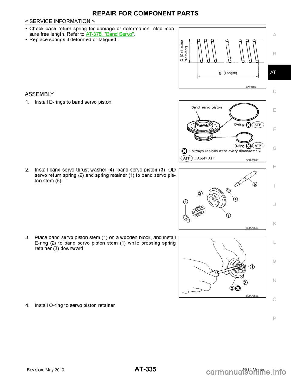
• Check each return spring for damage or deformation. Also mea- sure free length. Refer to AT-378, "
Band Servo".
• Replace springs if deformed or fatigued.
ASSEMBLY
1. Install D-rings to band servo piston.
2. Install band servo thrust washer (4), band servo piston (3), OD servo return spring (2) and spring retainer (1) to band servo pis-
ton stem (5).
3. Place band servo piston stem (1) on a wooden block, and install E-ring (2) to band servo piston stem (1) while pressing spring
retainer (3) downward.
4. Install O-ring to servo piston retainer.
SAT138D
SCIA3688E
SCIA7054E
SCIA7056E
Revision: May 2010 2011 Versa
Page 418 of 3787
![NISSAN TIIDA 2011 Service Repair Manual AUDIOAV-21
< SERVICE INFORMATION > [AUDIO WITHOUT NAVIGATION]
C
D
E
F
G H
I
J
L
M A
B
AV
N
O P
NOTE:
Noise resulting from variations in field strength, such as fading noise and multi-path noise, or e NISSAN TIIDA 2011 Service Repair Manual AUDIOAV-21
< SERVICE INFORMATION > [AUDIO WITHOUT NAVIGATION]
C
D
E
F
G H
I
J
L
M A
B
AV
N
O P
NOTE:
Noise resulting from variations in field strength, such as fading noise and multi-path noise, or e](/manual-img/5/57396/w960_57396-417.png)
AUDIOAV-21
< SERVICE INFORMATION > [AUDIO WITHOUT NAVIGATION]
C
D
E
F
G H
I
J
L
M A
B
AV
N
O P
NOTE:
Noise resulting from variations in field strength, such as fading noise and multi-path noise, or external noise
from trains and other sources. It is not a malfunction.
• Fading noise: This noise occurs because of variations in the field strength in a narrow range due to moun-
tains or buildings blocking the signal.
• Multi-path noise: This noise results from the waves sent directly from the broadcast station arriving at the antenna at a different time from the waves t hat reflect off of mountains or buildings.
Noise InspectionINFOID:0000000005931285
The vehicle itself can be a source of noise if noise prevention parts or electrical equipment is malfunctioning.
Check if noise is caused and/or changed by engine speed, ignition switch turned to each position, and opera-
tion of each piece of electrical equipment, and determine the cause.
NOTE:
The source of the noise can be found easily by listening to the noise while removing the fuses of electrical
components, one by one.
TYPE OF NOISE AND POSSIBLE CAUSE
No sound can be heard from one or several speakers. • Open or short in audio signal circuit between audio unit and front
speaker. Refer to AV- 2 4 , "
Sound Is Not Heard from Front Door
Speaker (Base System)" or AV- 2 6 , "Sound Is Not Heard from
Front Door Speaker or Tweeter (Premium System)" .
• Front speaker. Refer to AV- 2 4 , "
Sound Is Not Heard from Front
Door Speaker (Base System)" or AV- 2 6 , "Sound Is Not Heard
from Front Door Speaker or Tweeter (Premium System)" .
• Open or short in audio signal circuit between audio unit and rear
speaker. Refer to AV- 2 5 , "
Sound Is Not Heard from Rear Door
Speaker (Base System)" or AV- 2 7 , "Sound Is Not Heard from
Rear Door Speaker (Premium System)" .
• Rear speaker. Refer to AV- 2 5 , "
Sound Is Not Heard from Rear
Door Speaker (Base System)" or AV- 2 7 , "Sound Is Not Heard
from Rear Door Speaker (Premium System)" .
• Tweeter (mid level and premium system) AV- 2 6 , "
Sound Is Not
Heard from Front Door Speaker or Tweeter (Premium System)"
or AV- 2 7 , "
Sound Is Not Heard from Rear Door Speaker (Premi-
um System)" .
• Audio unit. Refer to AV- 2 9 , "
Removal and Installation" .
No sound can be heard from radio or noise is heard. • Antenna feeder. Refer to
AV- 3 3 , "
Location of Antenna" .
• Antenna. Refer to AV- 3 3 , "
Location of Antenna" .
• Audio unit. Refer to AV- 2 9 , "
Removal and Installation" .
Symptom
Check item
Occurrence condition Possible cause
Occurs only when engine is ON. A continuous growling noise occurs. The speed of
the noise varies with changes in the engine speed.
Ignition components
A whistling noise occurs while the engine speed is
high. A booming noise occurs while the engine is
running and the lighting switch is ON. Generator
Noise only occurs when various
electrical components are oper-
ating. A cracking or snapping sound occurs with the op-
eration of various switches.
Relay malfunction, radio malfunction
The noise occurs when various motors are operat-
ing. • Motor case ground
•Motor
The noise occurs constantly, not just under certain conditions. • Rear defogger coil malfunction
• Open circuit in printed heater
A cracking or snapping sound occurs while the vehicle is being driven, especially when
it is vibrating excessively. • Ground wire of body parts.
• Ground due to improper part installation
• Wiring connections or a short circuit
Revision: May 2010
2011 Versa
Page 451 of 3787
![NISSAN TIIDA 2011 Service Repair Manual AV-54
< SERVICE INFORMATION >[AUDIO WITH NAVIGATION]
AUDIO
System Description
INFOID:0000000006216702
AUDIO SYSTEM
Refer to Owners Manual for audio system operating instructions.
Navigation is built NISSAN TIIDA 2011 Service Repair Manual AV-54
< SERVICE INFORMATION >[AUDIO WITH NAVIGATION]
AUDIO
System Description
INFOID:0000000006216702
AUDIO SYSTEM
Refer to Owners Manual for audio system operating instructions.
Navigation is built](/manual-img/5/57396/w960_57396-450.png)
AV-54
< SERVICE INFORMATION >[AUDIO WITH NAVIGATION]
AUDIO
System Description
INFOID:0000000006216702
AUDIO SYSTEM
Refer to Owner's Manual for audio system operating instructions.
Navigation is built into AV control unit.
This navigation has the following functions.
• Full support for playback of music from iPod
® and USB device.
• High resolution full color touch panel 5 “WQVGA” display.
• FM/AM twin digital tuner.
• USB mass storage.
•XM traffic.
• POI Support is included. User POI download.
Power is supplied at all times
• through 20A fuse (No. 27, located in the fuse and fusible link box)
• to AV control unit terminal 19.
With the ignition switch in the ACC or ON position, power is supplied
• through 10A fuse [No. 20, located in the fuse block (J/B)]
• to AV control unit terminal 7.
Ground is supplied to
• to AV control unit terminals 20 and 32
• through grounds M57 and M61.
Then audio signals are supplied
• through AV control unit terminals 2, 3, 4, 5, 11, 12, 13 and 14
• to terminals + and - of front door speaker LH and RH
• to terminals + and - of front tweeter LH and RH and
• to terminals + and - of rear door speaker LH and RH.
STEERING WHEEL AUDIO CONTROL SWITCHES
When one of steering wheel audio control switches is pus hed, the resistance in steering switch circuit changes
depending on which button is pushed.
AWNIA2215GB
Revision: May 2010 2011 Versa
Page 465 of 3787
![NISSAN TIIDA 2011 Service Repair Manual AV-68
< SERVICE INFORMATION >[AUDIO WITH NAVIGATION]
AUDIO
NOTE:
Noise resulting from variations in field strength, such
as fading noise and multi-path noise, or external noise
from trains and other NISSAN TIIDA 2011 Service Repair Manual AV-68
< SERVICE INFORMATION >[AUDIO WITH NAVIGATION]
AUDIO
NOTE:
Noise resulting from variations in field strength, such
as fading noise and multi-path noise, or external noise
from trains and other](/manual-img/5/57396/w960_57396-464.png)
AV-68
< SERVICE INFORMATION >[AUDIO WITH NAVIGATION]
AUDIO
NOTE:
Noise resulting from variations in field strength, such
as fading noise and multi-path noise, or external noise
from trains and other sources, is not a malfunction.
• Fading noise: This noise occurs because of variations in the field strength in a narrow range due to moun- tains or buildings blocking the signal.
• Multi-path noise: This noise results from a time di fference between the broadcast waves directly from the
station arriving at the antenna and the waves reflected by mountains or buildings.
MALFUNCTION WITH USB
NOTE:
Check that there is no malfunction of USB equi pment main body before performing a diagnosis.
MALFUNCTION WITH AUXILIARY INPUT
NOTE:
Check that there is no malfunction of AUX equipment main body before performing a diagnosis.
MALFUNCTION WITH STEERING SWITCH
No sound can be heard from rear speakers. • Audio signal circuit between AV control unit and rear speakers. Refer to
AV- 7 2.
• Rear speaker. Refer to AV- 7 3
.
• AV control unit. Refer to AV- 7 3
.
No sound can be heard from radio or noise is heard. • Antenna feeder. Refer to AV- 9 1
.
• Roof antenna. Refer to AV- 9 1
.
• AV control unit. Refer to AV- 7 3
.
Speed dependent volume system does not function. • Vehicle speed signal circuit between combination meter and AV control
unit. Refer to DI-16
.
• AV control unit. Refer to AV- 7 3
.
• Combination meter. Refer to DI-20
.
There is no sound from the iPod
® or Aux jack. •iPod
® sound signal circuit between AV control unit and Auxiliary jack as-
sembly. Refer to AV- 6 9
.
• AV control unit. Refer to AV- 7 3
.
Symptom
Probable malfunction location
SymptomsCheck itemsProbable malfunction location / Action to
take
iPod
® or USB memory can not be
recognized. With iPod
® or USB
memory Connected,
check “USB Device” in
“SERVICE STATUS”,
“SERVICE MENU”. iPod
® or USB memory
name is displayed for
“USB Device”. • USB interface and AUX jack harness
• USB interface and AUX jack. Refer to
AV- 9 0
.
• AV control unit. Refer to AV- 7 3
.
“Removed” is displayed
for “USB Device”. • USB interface and AUX jack harness
• USB interface and AUX jack. Refer to
AV- 9 0
.
—— Generation of iPod
® not supported
SymptomsCheck items Probable malfunction location
No voice sound is heard when
AUX mode is selected. Voice sound is heard when other modes
are selected. • USB interface and AUX jack harness
• USB interface and AUX jack. Refer to
AV- 9 0
.
Symptoms Possible malfunction location / Action to take
All steering switches are not operated.
Steering switch. Refer to AV- 6 9
.
Only specified switch cannot be operated.
“SEEK UP”, “VOL UP” and “SOURCE” switches are not
operated.
“SOURCE”, “SEEK DOWN” and “VOL DOWN” switches
are not operated.
Revision: May 2010
2011 Versa
Page 506 of 3787
BCS-16
< SERVICE INFORMATION >
BCM (BODY CONTROL MODULE)
1: With Intelligent Key
2: Without Intelligent Key
3: Hatchback without Intelligent Key
4: Sedan without Intelligent Key
5: Hatchback
6: Sedan
7: With power door locks
8: With power windows
BCM Power Supply and Ground Circuit InspectionINFOID:0000000005929260
1.CHECK FUSES AND FUSIBLE LINK
• Check 40A fusible link (letter g , located in the fuse and fusible link box).
• Check 10A fuses [No. 6, 8 and 20, lo cated in the fuse block (J/B)].
OK or NG
OK >> GO TO 2.
NG >> If fuse is blown, be sure to eliminate cause of malfunction before installing new fuse. Refer to PG-
4, "Schematic" .
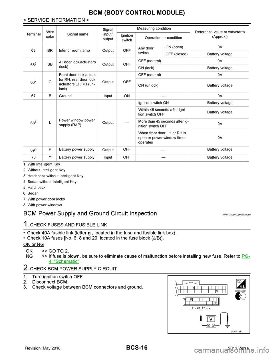
2.CHECK BCM POWER SUPPLY CIRCUIT
1. Turn ignition switch OFF.
2. Disconnect BCM.
3. Check voltage between BCM connectors and ground.
63 BR Interior room lamp Output OFF Any door
switchON (open)
0V
OFF (closed) Battery voltage
65
7SB All door lock actuators
(lock) Output OFFOFF (neutral)
0V
ON (lock) Battery voltage
66
7G Front door lock actua-
tor RH, rear door lock
actuators LH/RH (un-
lock) Output OFFOFF (neutral)
0V
ON (unlock) Battery voltage
67 B Ground Input ON—0V
68
8L Power window power
supply (RAP)
Output —Ignition switch ON
Battery voltage
Within 45 seconds after igni-
tion switch OFF Battery voltage
More than 45 seconds after ig-
nition switch OFF 0V
When front door LH or RH is
open or power window timer
operates 0V
69
8P Battery power supply OutputOFF
— Battery voltage
70 Y Battery power supply Input OFF —Battery voltage
Te r m i n a l
Wire
color Signal name Signal
input/
output Measuring condition
Reference value or waveform
(Approx.)
Ignition
switch Operation or condition
LIIA2415E
Revision: May 2010
2011 Versa
Page 518 of 3787
BL-8
< SERVICE INFORMATION >
SQUEAK AND RATTLE TROUBLE DIAGNOSES
If the noise can be duplicated easily during the test drive, to help identify the source of the noise, try to dupli-
cate the noise with the vehicle stopped by doing one or all of the following:
1) Close a door.
2) Tap or push/pull around the area where the noise appears to be coming from.
3) Rev the engine.
4) Use a floor jack to recreate vehicle “twist”.
5) At idle, apply engine load (electrical load, half-clutch on M/T model, drive position on A/T model).
6) Raise the vehicle on a hoist and hit a tire with a rubber hammer.
• Drive the vehicle and attempt to duplicate the conditions the customer states exist when the noise occurs.
• If it is difficult to duplicate the noise, drive the v ehicle slowly on an undulating or rough road to stress the
vehicle body.
CHECK RELATED SERVICE BULLETINS
After verifying the customer concern or symptom, chec k ASIST for Technical Service Bulletins (TSBs) related
to that concern or symptom.
If a TSB relates to the symptom, follo w the procedure to repair the noise.
LOCATE THE NOISE AND IDENTIFY THE ROOT CAUSE
1. Narrow down the noise to a general area.To help pinpoint the source of the noise, use a listening tool
(Chassis Ear: J-39570, Engine Ear: J-39565 and mechanic's stethoscope).
2. Narrow down the noise to a more specific area and identify the cause of the noise by:
• removing the components in the area that you suspect the noise is coming from.
Do not use too much force when removing clips and fasteners, otherwise clips and fasteners can be broken
or lost during the repair, resulting in the creation of new noise.
• tapping or pushing/pulling the component that you suspect is causing the noise.
Do not tap or push/pull the component with excessive force, otherwise the noise will be eliminated only tem-
porarily.
• feeling for a vibration with your hand by touching the component(s) that you suspect is (are) causing the
noise.
• placing a piece of paper between components that you suspect are causing the noise.
• looking for loose components and contact marks. Refer to BL-9, "
Generic Squeak and Rattle Troubleshooting".
REPAIR THE CAUSE
• If the cause is a loose component, tighten the component securely.
• If the cause is insufficient clearance between components:
- separate components by repositioning or loos ening and retightening the component, if possible.
- insulate components with a suitable insulator such as urethane pads, foam blocks, felt cloth tape or urethane tape. A NISSAN Squeak and Rattle Kit (J-43980) is av ailable through your authorized NISSAN Parts Depart-
ment.
CAUTION:
Do not use excessive force as many components are constructed of plastic and may be damaged.
Always check with the Parts Department for the latest parts information.
The following materials are contained in the NISSAN Squeak and Rattle Kit (J-43980). Each item can be
ordered separately as needed.
URETHANE PADS [1.5 mm (0.059 in) thick]
Insulates connectors, harness, etc.
76268-9E005: 100 ×135 mm (3.94× 5.31 in)/76884-71L01: 60 ×85 mm (2.36 ×3.35 in)/76884-71L02: 15 ×25
mm (0.59× 0.98 in)
INSULATOR (Foam blocks)
Insulates components from contact. Can be used to fill space behind a panel.
73982-9E000: 45 mm (1.77 in) thick, 50 ×50 mm (1.97 ×1.97 in)/73982-50Y00: 10 mm (0.39 in) thick,
50× 50 mm (1.97 ×1.97 in)
INSULATOR (Light foam block)
80845-71L00: 30 mm (1.18 in) thick, 30 ×50 mm (1.18 ×1.97 in)
FELT CLOTH TAPE
Used to insulate where movemen t does not occur. Ideal for instrument panel applications.
68370-4B000: 15 ×25 mm (0.59× 0.98 in) pad/68239-13E00: 5 mm (0.20 in ) wide tape roll. The following
materials not found in the kit can also be used to repair squeaks and rattles.
UHMW (TEFLON) TAPE
Insulates where slight movement is present. Ideal for inst rument panel applications.
Revision: May 2010 2011 Versa
Page 519 of 3787
SQUEAK AND RATTLE TROUBLE DIAGNOSESBL-9
< SERVICE INFORMATION >
C
DE
F
G H
J
K L
M A
B
BL
N
O P
SILICONE GREASE
Used instead of UHMW tape that will be visible or not fit.
Note: Will only last a few months.
SILICONE SPRAY
Use when grease cannot be applied.
DUCT TAPE
Use to eliminate movement.
CONFIRM THE REPAIR
Confirm that the cause of a noise is repaired by test driving the vehicle. Operate the vehicle under the same
conditions as when the noise originally occurred. Refer to the notes on the Diagnostic Worksheet.
Generic Squeak and Rattle TroubleshootingINFOID:0000000005929274
Refer to Table of Contents for specific component removal and installation information.
INSTRUMENT PANEL
Most incidents are caused by contact and movement between:
1. The cluster lid A and instrument panel
2. Acrylic lens and combination meter housing
3. Instrument panel to front pillar garnish
4. Instrument panel to windshield
5. Instrument panel mounting pins
6. Wiring harnesses behind the combination meter
7. A/C defroster duct and duct joint
These incidents can usually be located by tapping or moving the components to duplicate the noise or by
pressing on the components while driving to stop the noi se. Most of these incidents can be repaired by apply-
ing felt cloth tape or silicone spray (in hard to reach areas). Urethane pads can be used to insulate wiring har-
ness.
CAUTION:
Do not use silicone spray to isolate a squeak or ra ttle. If you saturate the area with silicone, you will
not be able to recheck the repair.
CENTER CONSOLE
Components to pay attention to include:
1. Shift selector cover to finisher
2. A/C control unit and cluster lid C
3. Wiring harnesses behind audio and A/C control unit
The instrument panel repair and isolation pr ocedures also apply to the center console.
DOORS
Pay attention to the:
1. Finisher and inner panel making a slapping noise
2. Inside handle escutcheon to door finisher
3. Wiring harnesses tapping
4. Door striker out of alignment causing a popping noise on starts and stops
Tapping or moving the components or pressing on them while driving to duplicate the conditions can isolate
many of these incidents. You can usually insulate the ar eas with felt cloth tape or insulator foam blocks from
the NISSAN Squeak and Rattle Kit (J-43980) to repair the noise.
TRUNK
Trunk noises are often caused by a loose jack or loose items put into the trunk by the owner.
In addition look for:
1. Trunk lid bumpers out of adjustment
2. Trunk lid striker out of adjustment
3. The trunk lid torsion bars knocking together
4. A loose license plate or bracket
Revision: May 2010 2011 Versa