2011 NISSAN TIIDA recommended
[x] Cancel search: recommendedPage 2 of 3787

-2
This manual contains maintenance and repair procedures for the
2011 NISSAN VERSA.
In order to assure your safety and the efficient functioning of the vehicle,
this manual should be read thoroughly. It is especially important that the
PRECAUTIONS in the GI section be completely understood before starting
any repair task.
All information in this manual is based on the latest product information
at the time of publication. The right is reserved to make changes in specifi-
cations and methods at any time without notice.
IMPORTANT SAFETY NOTICE
The proper performance of service is essential for both the safety of
the technician and the efficient functioning of the vehicle.
The service methods in this Service Manual are described in such a
manner that the service may be performed safely and accurately.
Service varies with the procedures used, the skills of the technician
and the tools and parts available. Accordingly, anyone using service
procedures, tools or parts which are not specifically recommended
by NISSAN must first be completely satisfied that neither personal
safety nor the vehicle’s safety will be jeopardized by the service
method selected.
Page 9 of 3787

QUICK REFERENCE INDEX: VERSA
2011
MR18DE
TypeWith ABS or VDC/TCS/ABSWithout ABS
Front brake Brake model AD22VK
Cylinder bore diameter 53.97 mm (2.125 in)
Pad
Length × width × thickness 11 5 . 0 m m
× 41.0 mm × 9.0 mm
(4.528 in × 1.614 in × 0.354 in)
Rotor outer diameter × thickness 260 mm × 22.0 mm (10.24 in × 0.866 in)
Rear brake Brake model LT20
Cylinder bore diameter 15.87 mm (0.625 in)17.46 mm (0.687 in)
Drum inner diameter 203 mm (7.992 in)
Master cylinder Cylinder bore diameter 22.22 mm (0.875 in)
Brake booster Booster model C255
Diaphragm diameter 255 mm (10.04 in)
Recommended brake fluid DOT 3
Front brake Brake modelCLZ25VF
Cylinder bore diameter 57.2 mm (2.252 in)
Pad
Length × width × thickness 125.6 mm
× 48.0 mm × 9.5 mm
(4.945 in × 1.890 in × 0.374 in)
Rotor outer diameter × thickness 280 mm × 24.0 mm (11.02 in × 0.945 in)
Rear brake Brake model LT23
Cylinder bore diameter 19.06 mm (0.750 in)
Drum inner diameter 228.6 mm (9.000 in)
Master cylinder Cylinder bore diameter 23.81 ± 0.015 mm (0.937 ± 0.001 in)
Brake booster Booster model C255
Diaphragm diameter 255 mm (10.04 in)
Recommended brake fluid DOT 3
Page 26 of 3787
PRECAUTIONSAT-9
< SERVICE INFORMATION >
DE
F
G H
I
J
K L
M A
B
AT
N
O P
• Gaskets, seals and O-rings should be replaced any time the A/T is disassembled.
• It is very important to perform func tional tests whenever they are indicated.
• The valve body contains precision parts and requires extreme care when parts are removed and serviced.
Place disassembled valve body parts in order for easier and proper assembly. Care will also prevent springs
and small parts from becoming scattered or lost.
• Properly installed valves, sleeves, plugs, etc. will slide along bores in valve body under their own weight.
• Before assembly, apply a coat of recommended ATF to all parts. Apply petroleum jelly to protect O-rings and seals, or hold bearings and washers in pl ace during assembly. Do not use grease.
• Extreme care should be taken to avoid damage to O-rings, seals and gaskets when assembling.
• Clean or replace ATF cooler if excessive foreign material is found in oil pan or clogging strainer. Refer to AT-
18, "A/T Fluid Cooler Cleaning".
• After overhaul, refill the A/T with new ATF.
• When the A/T drain plug is removed, only some of the fluid is drained. Old A/T fluid will remain in torque con- verter and ATF cooling system.
Always follow the procedures under “Changing A/T Fluid” in the AT section when changing A/T fluid. Refer to
AT-17, "
Changing A/T Fluid", AT-17, "Checking A/T Fluid".
Service Notice or PrecautionINFOID:0000000005928067
ATF COOLER SERVICE
If A/T fluid contains frictional material (clutches, bands, etc.), or if an A/T is repaired, overhauled, or replaced,
inspect and clean the A/T oil cooler mounted in the radiator or replace the radiator. Flush cooler lines using
cleaning solvent and compressed air after repair. Check Service Bulletins for latest A/T oil cooler cleaning pro-
cedure. For radiator replacement, refer to CO-16, "
Removal and Installation" (HR16DE engine models), CO-
40, "Removal and Installation" (MR18DE engine models).
TORQUE CONVERTER SERVICE
The torque converter should be replaced under any of the following conditions:
• External leaks in the hub weld area.
• Converter hub is scored or damaged.
• Converter pilot is broken, damaged or fits poorly into crankshaft.
• Steel particles are found after flushing the cooler and cooler lines.
• Pump is damaged or steel particles are found in the converter.
• Vehicle has TCC shudder and/or no TCC apply. Replace only after all hydraulic and electrical diagnoses
have been made. (Converter clutch material may be glazed.)
• Converter is contaminated with engi ne coolant containing antifreeze.
• Internal malfunction of stator roller clutch.
• Heavy clutch debris due to overheating (blue converter).
• Steel particles or clutch lining material found in flui d filter or on magnet when no internal parts in unit are
worn or damaged — indicates that lining material came from converter.
The torque converter should not be replaced if:
• The fluid has an odor, is discolored, and there is no evidence of metal or clutch facing particles.
• The threads in one or more of the converter bolt holes are damaged.
• A/T malfunction did not display evidence of damaged or worn internal parts, steel particles or clutch plate lin-
ing material in unit and inside the fluid filter.
• Vehicle has been exposed to high mileage (only). The e xception may be where the torque converter clutch
dampener plate lining has seen excess wear by vehicles operated in heavy and/or constant traffic, such as
taxi, delivery or police use.
OBD-II SELF-DIAGNOSIS
• A/T self-diagnosis is performed by the TCM in combination with the ECM. The results can be read through the blinking pattern of the OD OFF indicator lamp or the malfunction indicator lamp (MIL). Refer to the table
on AT-82, "
Diagnosis Procedure without CONSULT-III" for the indicator used to display each self-diagnostic
result.
• The self-diagnostic results indicated by the MIL are automatically stored in both the ECM and TCM memo- ries.
Always perform the procedure “HOW TO ERASE DTC” on AT-39, "
OBD-II Diagnostic Trouble Code
(DTC)" to complete the repair and avoid unnecessary blinking of the MIL.
• The following self-diagnostic items can be detected us ing ECM self-diagnostic results mode* only when the
OD OFF indicator lamp does not indicate any malfunctions.
- Transmission range switch
- A/T 1GR, 2GR, 3GR, or 4GR function
Revision: May 2010 2011 Versa
Page 372 of 3787
ASSEMBLYAT-355
< SERVICE INFORMATION >
DE
F
G H
I
J
K L
M A
B
AT
N
O P
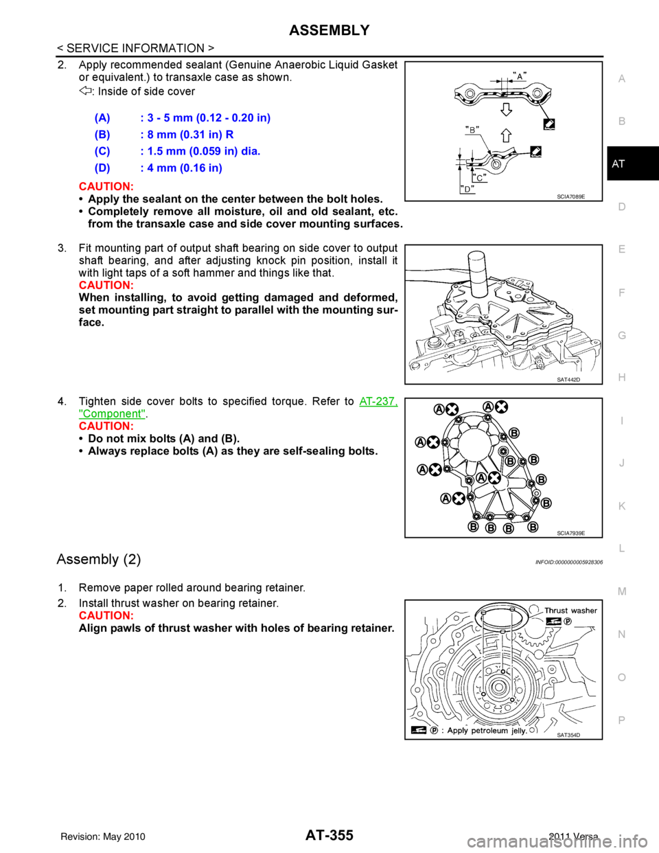
2. Apply recommended sealant (Genuine Anaerobic Liquid Gasket or equivalent.) to transaxle case as shown.
: Inside of side cover
CAUTION:
• Apply the sealant on the center between the bolt holes.
• Completely remove all moisture, oil and old sealant, etc. from the transaxle case and side cover mounting surfaces.
3. Fit mounting part of output shaft bearing on side cover to output shaft bearing, and after adjusting knock pin position, install it
with light taps of a soft hammer and things like that.
CAUTION:
When installing, to avoid getting damaged and deformed,
set mounting part straight to parallel with the mounting sur-
face.
4. Tighten side cover bolts to specified torque. Refer to AT-237,
"Component".
CAUTION:
• Do not mix bolts (A) and (B).
• Always replace bolts (A) as they are self-sealing bolts.
Assembly (2)INFOID:0000000005928306
1. Remove paper rolled around bearing retainer.
2. Install thrust washer on bearing retainer. CAUTION:
Align pawls of thrust washer with holes of bearing retainer.(A) : 3 - 5 mm (0.12 - 0.20 in)
(B) : 8 mm (0.31 in) R
(C) : 1.5 mm (0.059 in) dia.
(D) : 4 mm (0.16 in)
SCIA7089E
SAT442D
SCIA7939E
SAT354D
Revision: May 2010
2011 Versa
Page 384 of 3787
ASSEMBLYAT-367
< SERVICE INFORMATION >
DE
F
G H
I
J
K L
M A
B
AT
N
O P
20. Install O-ring on differential oil port of transaxle case.
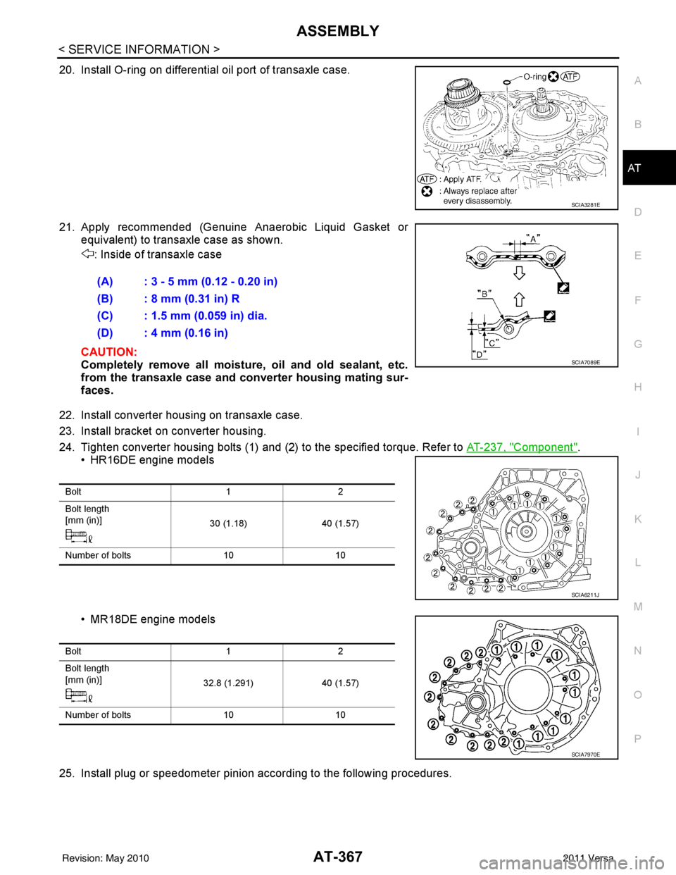
21. Apply recommended (Genuine Anaerobic Liquid Gasket or equivalent) to transaxle case as shown.
: Inside of transaxle case
CAUTION:
Completely remove all moisture, oil and old sealant, etc.
from the transaxle case and converter housing mating sur-
faces.
22. Install converter housing on transaxle case.
23. Install bracket on converter housing.
24. Tighten converter housing bolts (1) and (2) to the specified torque. Refer to AT-237, "
Component".
• HR16DE engine models
• MR18DE engine models
25. Install plug or speedometer pinion according to the following procedures.
SCIA3281E
(A) : 3 - 5 mm (0.12 - 0.20 in)
(B) : 8 mm (0.31 in) R
(C) : 1.5 mm (0.059 in) dia.
(D) : 4 mm (0.16 in)
SCIA7089E
Bolt 12
Bolt length
[mm (in)] 30 (1.18)40 (1.57)
Number of bolts 1010
SCIA6211J
Bolt 12
Bolt length
[mm (in)] 32.8 (1.291)40 (1.57)
Number of bolts 1010
SCIA7970E
Revision: May 2010 2011 Versa
Page 390 of 3787

SERVICE DATA AND SPECIFICATIONS (SDS)AT-373
< SERVICE INFORMATION >
DE
F
G H
I
J
K L
M A
B
AT
N
O P
SERVICE DATA AND SPECIFICATIONS (SDS)
General SpecificationINFOID:0000000005928309
*: Refer to MA-14.
Vehicle Speed at Which Gear Shifting OccursINFOID:0000000005928310
HR16DE engine models
MR18DE engine models
• At half throttle, the accelerator opening is 4/8 of the full opening.
Vehicle Speed at When Lock-up Occurs/ReleasesINFOID:0000000005928311
HR16DE engine models
MR18DE engine models
Engine HR16DEMR18DE
Automatic transaxle model RE4F03B
Automatic transaxle assembly Model code number 3CX3D, 3CX3E3CX0D
Transaxle gear ratio 1st
2.861
2nd 1.562
3rd 1.000
4th 0.697
Reverse 2.310
Final drive 4.072
Recommended fluid Genuine NISSAN Matic S ATF (Continental U.S. and Alaska) or
Canada NISSAN Automatic Transmission Fluid*
Fluid capacity [ (US qt, Imp qt)] 7.7 (8-1/8, 6-3/4)
7.9 (8-3/8, 7)
Throttle position Vehicle speed km/h (MPH)
D1 → D2D2 → D3D3 → D4D4 → D3D3 → D2D2 → D1
Full throttle 49 - 57
(31 - 35) 93 - 101
(58 - 62) 148 - 156
(92 - 96) 144 - 152
(90 - 94) 82 - 90
(51 - 55) 39 - 47
(25 - 29)
Half throttle 35 - 43
(22 - 26) 59 - 67
(37 - 41) 117 - 125
(73 - 77) 59 - 67
(37 - 41) 34 - 42
(22 - 26) 15 - 23
(10 - 14)
Throttle position Vehicle speed km/h (MPH)
D
1 → D2D2 → D3D3 → D4D4 → D3D3 → D2D2 → D1
Full throttle 51 - 59
(32 - 37) 97 - 105
(60 - 65) 154 - 162
(96 - 101) 150 - 158
(93 - 98) 87 - 95
(54 - 59) 40 - 48
(25 - 30)
Half throttle 34 - 42
(21 - 26) 62 - 70
(39 - 43) 124 - 132
(77 - 82) 69 - 77
(43 - 48) 36 - 44
(22 - 27) 19 - 27
(12 - 17)
Throttle position Selector lever position Vehicle speed km/h (MPH)
Lock-up ON Lock-up OFF
2.0/8 “D” position
73 - 81 (46 - 50) 49 - 57 (31 - 35)
“D” position (OD OFF) 86 - 94 (53 - 58) 82 - 90 (51 - 55)
Throttle position Selector lever position Vehicle speed km/h (MPH)
Lock-up ON Lock-up OFF
2.0/8 “D” position
86 - 94 (53 - 58) 59 - 67 (37 - 42)
“D” position (OD OFF) 86 - 94 (53 - 58) 83 - 91 (52 - 57)
Revision: May 2010 2011 Versa
Page 783 of 3787
BODY REPAIRBL-273
< SERVICE INFORMATION >
C
DE
F
G H
J
K L
M A
B
BL
N
O P
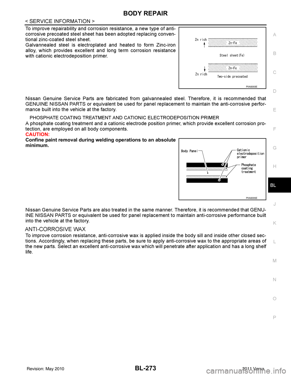
To improve repairability and corrosion resistance, a new type of anti-
corrosive precoated steel sheet has been adopted replacing conven-
tional zinc-coated steel sheet.
Galvannealed steel is electroplated and heated to form Zinc-iron
alloy, which provides excellent and long term corrosion resistance
with cationic electrodeposition primer.
Nissan Genuine Service Parts are fabricated from galvannealed steel. Therefore, it is recommended that
GENUINE NISSAN PARTS or equivalent be used for panel replacement to maintain the anti-corrosive perfor-
mance built into the vehicle at the factory.
PHOSPHATE COATING TREATMENT AND CA TIONIC ELECTRODEPOSITION PRIMER
A phosphate coating treatment and a cationic electrode posit ion primer, which provide excellent corrosion pro-
tection, are employed on all body components.
CAUTION:
Confine paint removal during weld ing operations to an absolute
minimum.
Nissan Genuine Service Parts are also treated in the same manner. Therefore, it is recommended that GENU-
INE NISSAN PARTS or equivalent be used for panel repl acement to maintain anti-corrosive performance built
into the vehicle at the factory.
ANTI-CORROSIVE WAX
To improve corrosion resistance, anti-corrosive wax is applied inside the body sill and inside other closed sec-
tions. Accordingly, when replacing these parts, be sure to apply anti-corrosive wax to the appropriate areas of
the new parts. Select an excellent anti-corrosive wax which will penetrate after application and has a long shelf
life.
PIIA0093E
PIIA0095E
Revision: May 2010 2011 Versa
Page 816 of 3787
BL-306
< SERVICE INFORMATION >
BODY REPAIR
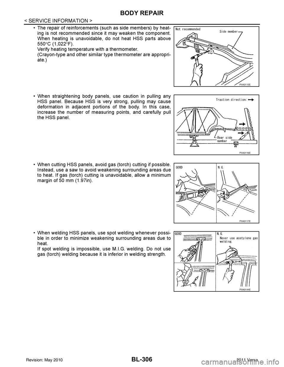
• The repair of reinforcements (such as side members) by heat-ing is not recommended since it may weaken the component.
When heating is unavoidable, do not heat HSS parts above
550° C (1,022° F).
Verify heating temperature with a thermometer.
(Crayon-type and other similar type thermometer are appropri-
ate.)
• When straightening body panels, use caution in pulling any HSS panel. Because HSS is very strong, pulling may cause
deformation in adjacent portions of the body. In this case,
increase the number of measuring points, and carefully pull
the HSS panel.
• When cutting HSS panels, avoid gas (torch) cutting if possible. Instead, use a saw to avoid weakening surrounding areas due
to heat. If gas (torch) cutting is unavoidable, allow a minimum
margin of 50 mm (1.97in).
• When welding HSS panels, use spot welding whenever possi- ble in order to minimize weakening surrounding areas due to
heat.
If spot welding is impossible, use M.I.G. welding. Do not use
gas (torch) welding because it is inferior in welding strength.
PIIA0115E
PIIA0116E
PIIA0117E
PIIA0144E
Revision: May 2010 2011 Versa