Page 1 of 3787

-1
QUICK REFERENCE INDEX
AGENERAL INFORMATIONGIGeneral Information
BENGINEEMEngine Mechanical
LUEngine Lubrication System
COEngine Cooling System
ECEngine Control System
FLFuel System
EXExhaust System
ACCAccelerator Control System
CTRANSMISSION/
TRANSAXLECLClutch System
MTManual Transaxle
ATAutomatic Transaxle
CVTCVT
DDRIVELINE/AXLEFAXFront Axle
RAXRear Axle
ESUSPENSIONFSUFront Suspension
RSURear Suspension
WTRoad Wheels & Tires
FBRAKESBRBrake System
PBParking Brake System
BRCBrake Control System
GSTEERINGPSPower Steering System
STCSteering Control System
HRESTRAINTSSBSeat Belts
SRSSupplemental Restraint System (SRS)
IBODYBLBody, Lock & Security System
GWGlasses, Window System & Mirrors
RFRoof
EIExterior & Interior
IPInstrument Panel
SESeat
JAIR CONDITIONERMTCManual Air Conditioner
KELECTRICALSCStarting & Charging System
LTLighting System
DIDriver Information System
WWWiper, Washer & Horn
BCSBody Control System
LANLAN System
AVAudio Visual, Navigation & Telephone System
ACSAuto Cruise Control System
PGPower Supply, Ground & Circuit Elements
LMAINTENANCEMAMaintenance
Edition: May 2010
Revision: May 2010
Publication No. SM1E-1C11U0
B
D
© 2010 NISSAN NORTH AMERICA, INC.
All rights reserved. No part of this Service Manual may be reproduced or stored in a retrieval system, or transmitted in any
form, or by any means, electronic, mechanical, photo-copying, recording or otherwise, without the prior written permission
of Nissan North America Inc.
A
C
E
F
G
H
I
J
K
L
M
Page 34 of 3787

A/T FLUIDAT-17
< SERVICE INFORMATION >
DE
F
G H
I
J
K L
M A
B
AT
N
O P
A/T FLUID
Checking A/T FluidINFOID:0000000005928070
1. Warm up engine.
2. Check for A/T fluid leakage.
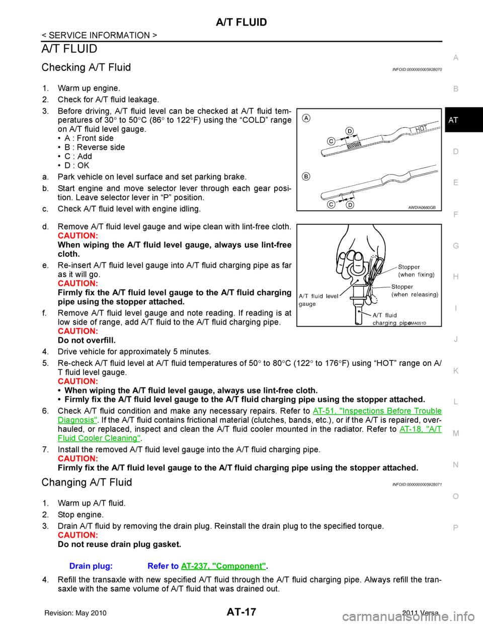
3. Before driving, A/T fluid level can be checked at A/T fluid tem- peratures of 30° to 50°C (86° to 122° F) using the “COLD” range
on A/T fluid level gauge.
• A : Front side
• B : Reverse side
•C : Add
• D : OK
a. Park vehicle on level surface and set parking brake.
b. Start engine and move selector lever through each gear posi- tion. Leave selector lever in “P” position.
c. Check A/T fluid level with engine idling.
d. Remove A/T fluid level gauge and wipe clean with lint-free cloth. CAUTION:
When wiping the A/T fluid l evel gauge, always use lint-free
cloth.
e. Re-insert A/T fluid level gauge into A/T fluid charging pipe as far as it will go.
CAUTION:
Firmly fix the A/T fluid level ga uge to the A/T fluid charging
pipe using the stopper attached.
f. Remove A/T fluid level gauge and note reading. If reading is at low side of range, add A/T fluid to the A/T fluid charging pipe.
CAUTION:
Do not overfill.
4. Drive vehicle for approximately 5 minutes.
5. Re-check A/T fluid level at A/T fluid temperatures of 50° to 80 °C (122° to 176°F) using “HOT” range on A/
T fluid level gauge.
CAUTION:
• When wiping the A/T fluid level gauge, always use lint-free cloth.
• Firmly fix the A/T fluid level ga uge to the A/T fluid charging pipe using the stopper attached.
6. Check A/T fluid condition and make any necessary repairs. Refer to AT-51, "
Inspections Before Trouble
Diagnosis". If the A/T fluid contains frictional material (clutches, bands, etc.), or if the A/T is repaired, over-
hauled, or replaced, inspect and clean the A/T fluid cooler mounted in the radiator. Refer to AT-18, "
A/T
Fluid Cooler Cleaning".
7. Install the removed A/T fluid level gauge into the A/T fluid charging pipe. CAUTION:
Firmly fix the A/T fluid level gaug e to the A/T fluid charging pipe using the stopper attached.
Changing A/T FluidINFOID:0000000005928071
1. Warm up A/T fluid.
2. Stop engine.
3. Drain A/T fluid by removing the drain plug. Re install the drain plug to the specified torque.
CAUTION:
Do not reuse drain plug gasket.
4. Refill the transaxle with new specified A/T fluid through the A/T fluid charging pipe. Always refill the tran- saxle with the same volume of A/T fluid that was drained out.
AWDIA0660GB
SMA051D
Drain plug: Refer to AT-237, "Component".
Revision: May 2010 2011 Versa
Page 38 of 3787
A/T CONTROL SYSTEMAT-21
< SERVICE INFORMATION >
DE
F
G H
I
J
K L
M A
B
AT
N
O P
A/T CONTROL SYSTEM
Cross-Sectional ViewINFOID:0000000005928073
HR16DE engine models
SCIA7651J
1. Converter housing 2. Oil pump3. Brake band
4. Reverse clutch 5. High clutch6. Front planetary gear
7. Low one-way clutch 8. Rear planetary gear9. Forward clutch
10. Overrun clutch 11. Low & reverse brake12. Output gear
13. Band servo piston 14. Reverse clutch drum15. Side cover
16. Idler gear 17. Forward one-way clutch 18. Transaxle case
19. Reduction pinion gear 20. Final gear 21. Differential case
22. Input shaft 23. Torque converter
Revision: May 2010 2011 Versa
Page 39 of 3787
AT-22
< SERVICE INFORMATION >
A/T CONTROL SYSTEM
MR18DE engine models
Shift MechanismINFOID:0000000005928074
CONSTRUCTION
SCIA7938E
1. Converter housing2. Oil pump3. Brake band
4. Reverse clutch 5. High clutch6. Front planetary gear
7. Low one-way clutch 8. Rear planetary gear9. Forward clutch
10. Overrun clutch 11. Low & reverse brake12. Output gear
13. Band servo piston 14. Reverse clutch drum15. Side cover
16. Idler gear 17. Forward one-way clutch 18. Transaxle case
19. Reduction pinion gear 20. Final gear21. Differential case
22. Input shaft 23. Torque converter
Revision: May 2010 2011 Versa
Page 45 of 3787
AT-28
< SERVICE INFORMATION >
A/T CONTROL SYSTEM
“D4” (OD) Position
SAT379J
•High clutch
• Brake band
• Forward clutch (Does not affect power
transmission) Input power is transmitted to front carrier through high clutch.
This front carrier turns around the sun gear which is fixed by brake band and makes
front internal gear (output) turn faster.
Engine brake At D
4 position, there is no one-way clutch in the power transaxle line and engine brake
can be obtained when decelerating.
Revision: May 2010 2011 Versa
Page 46 of 3787
A/T CONTROL SYSTEMAT-29
< SERVICE INFORMATION >
DE
F
G H
I
J
K L
M A
B
AT
N
O P
“R” Position
SAT380J
•
Reverse clutch
• Low & reverse brake Front planetary carrier is stationary because of the operation of low and reverse brake.
Input power is transmitted to front sun gear through reverse clutch, which drives front
internal gear in the opposite direction.
Engine brake As there is no one-way clutch in the power transaxle line, engine brake can be obtained
when decelerating.
Revision: May 2010
2011 Versa
Page 247 of 3787

AT-230
< SERVICE INFORMATION >
ON-VEHICLE SERVICE
REMOVAL AND INSTALLATION
Removal
1. Remove front drive shaft. Refer to FA X - 9.
2. Remove differential side oil seals using a suitable tool. CAUTION:
Be careful not to scratch transaxle case and converter
housing.
Installation
Installation is in the reverse order of removal.
NOTE:
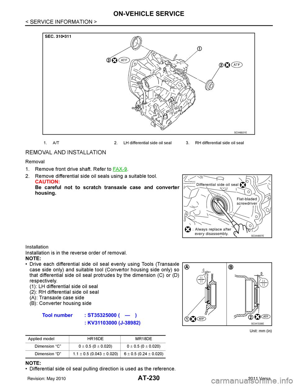
• Drive each differential side oil seal evenly using Tools (Transaxlecase side only) and suitable tool (Convertor housing side only) so
that differential side oil seal prot rudes by the dimension (C) or (D)
respectively.
(1): LH differential side oil seal
(2): RH differential side oil seal
(A): Transaxle case side
(B): Converter housing side
Unit: mm (in)
NOTE:
• Differential side oil seal pulling direction is used as the reference.
1. A/T 2. LH differential side oil seal 3. RH differential side oil seal
SCIA8021E
SCIA4857E
Tool number : ST35325000 ( — )
: KV31103000 (J-38982)
Applied model HR16DEMR18DE
Dimension “C” 0 ± 0.5 (0 ± 0.020) 0 ± 0.5 (0 ± 0.020)
Dimension “D” 1.1 ± 0.5 (0.043 ± 0.020) 6 ± 0.5 (0.24 ± 0.020)
SCIA7226E
Revision: May 2010 2011 Versa
Page 251 of 3787

AT-234
< SERVICE INFORMATION >
TRANSAXLE ASSEMBLY
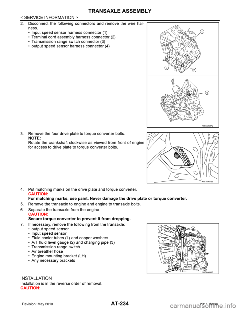
2. Disconnect the following connectors and remove the wire har-ness.
• Input speed sensor harness connector (1)
• Terminal cord assembly harness connector (2)
• Transmission range switch connector (3)
• output speed sensor harness connector (4)
3. Remove the four drive plate to torque converter bolts. NOTE:
Rotate the crankshaft clockwise as viewed from front of engine
for access to drive plate to torque converter bolts.
4. Put matching marks on the drive plate and torque converter. CAUTION:
For matching marks, use paint. Never dama ge the drive plate or torque converter.
5. Remove the transaxle to engine and engine to transaxle bolts.
6. Separate the transaxle from the engine. CAUTION:
Secure torque converter to prevent it from dropping.
7. If necessary, remove the following from the transaxle: • output speed sensor
• Input speed sensor
• Fluid cooler tubes (1) and copper washers
• A/T fluid level gauge (2) and charging pipe (3)
• Transmission range switch
• Air breather hose
• Engine mounting bracket (LH)
• Any necessary brackets
INSTALLATION
Installation is in the reverse order of removal.
CAUTION:
WCIA0647E
WCIA0616E
WCIA0648E
Revision: May 2010 2011 Versa