2011 NISSAN TIIDA Top support
[x] Cancel search: Top supportPage 98 of 3787

TROUBLE DIAGNOSISAT-81
< SERVICE INFORMATION >
DE
F
G H
I
J
K L
M A
B
AT
N
O P
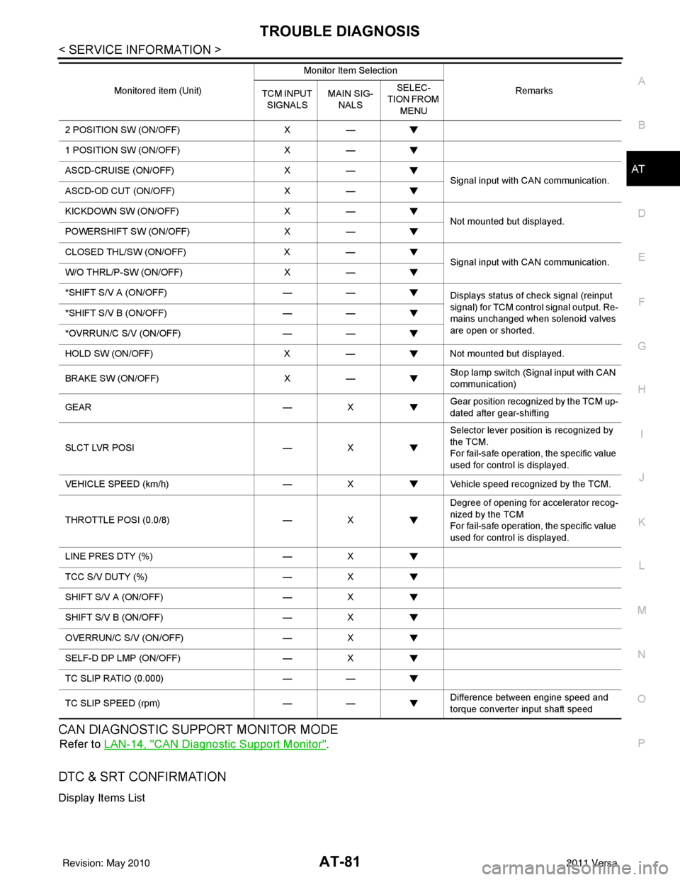
CAN DIAGNOSTIC SUPPORT MONITOR MODE
Refer to LAN-14, "CAN Diagnostic Support Monitor".
DTC & SRT CONFIRMATION
Display Items List
2 POSITION SW (ON/OFF) X—
1 POSITION SW (ON/OFF) X—
ASCD-CRUISE (ON/OFF) X—
Signal input with CAN communication.
ASCD-OD CUT (ON/OFF) X—
KICKDOWN SW (ON/OFF) X—
Not mounted but displayed.
POWERSHIFT SW (ON/OFF) X—
CLOSED THL/SW (ON/OFF) X—
Signal input with CAN communication.
W/O THRL/P-SW (ON/OFF) X—
*SHIFT S/V A (ON/OFF) ——
Displays status of check signal (reinput
signal) for TCM control signal output. Re-
mains unchanged when solenoid valves
are open or shorted.
*SHIFT S/V B (ON/OFF)
——
*OVRRUN/C S/V (ON/OFF) ——
HOLD SW (ON/OFF) X— Not mounted but displayed.
BRAKE SW (ON/OFF) X— Stop lamp switch (Signal input with CAN
communication)
GEAR —X Gear position recognized by the TCM up-
dated after gear-shifting
SLCT LVR POSI —X Selector lever position is recognized by
the TCM.
For fail-safe operation, the specific value
used for control is displayed.
VEHICLE SPEED (km/h) —X Vehicle speed reco gnized by the TCM.
THROTTLE POSI (0.0/8) —X Degree of opening for accelerator recog-
nized by the TCM
For fail-safe operation, the specific value
used for control is displayed.
LINE PRES DTY (%) —X
TCC S/V DUTY (%) —X
SHIFT S/V A (ON/OFF) —X
SHIFT S/V B (ON/OFF) —X
OVERRUN/C S/V (ON/OFF) —X
SELF-D DP LMP (ON/OFF) —X
TC SLIP RATIO (0.000) ——
TC SLIP SPEED (rpm) —— Difference between engine speed and
torque converter input shaft speed
Monitored item (Unit)
Monitor Item Selection
Remarks
TCM INPUT
SIGNALS MAIN SIG-
NALS SELEC-
TION FROM
MENU
Revision: May 2010 2011 Versa
Page 511 of 3787

BL-1
BODY
C
DE
F
G H
J
K L
M
SECTION BL
A
B
BL
N
O P
CONTENTS
BODY, LOCK & SECURITY SYSTEM
SERVICE INFORMATION .. ..........................4
PRECAUTIONS .............................................. .....4
Precaution for Supplemental Restraint System
(SRS) "AIR BAG" and "SEAT BELT PRE-TEN-
SIONER" ............................................................. ......
4
Precaution Necessary for Steering Wheel Rota-
tion After Battery Disconnect ............................... ......
4
Precaution for Procedure without Cowl Top Cover ......5
Precaution for Work ..................................................5
PREPARATION ...................................................6
Special Service Tool ........................................... ......6
Commercial Service Tool ..........................................6
SQUEAK AND RATTLE TROUBLE DIAG-
NOSES ................................................................
7
Work Flow ........................................................... ......7
Generic Squeak and Rattle Troubleshooting ............9
Diagnostic Worksheet .............................................11
HOOD .................................................................13
Fitting Adjustment ............................................... ....13
Removal and Installation .........................................14
Removal and Installation of Hood Lock Control .. ....15
Hood Lock Control Inspection .................................17
RADIATOR CORE SUPPORT ....................... ....19
Removal and Installation .........................................19
FRONT FENDER ................................................21
Removal and Installation .........................................21
POWER DOOR LOCK SYSTEM .................... ....22
Component Parts and Harness Connector Loca-
tion ...................................................................... ....
22
System Description .................................................23
CAN Communication System Description ...............25
Schematic ...............................................................26
Wiring Diagram - D/LOCK - .....................................27
Schematic ...............................................................31
Wiring Diagram - D/LOCK - .....................................32
Terminal and Reference Value for BCM ..................37
Work Flow ............................................................ ....41
CONSULT-III Function (BCM) .................................41
Trouble Diagnosis Symptom Chart ...................... ....43
BCM Power Supply and Ground Circuit Inspection
....
43
Door Switch Check (Hatchback) ..............................44
Door Switch Check (Sedan) ....................................47
Key Switch (Insert) Check .......................................48
Door Lock and Unlock Switch Check ......................49
Front Door Lock Assembly LH (Actuator) Check .....52
Front Door Lock Assembly RH (Actuator) Check ....53
Rear Door Lock Actuator LH/RH Check .............. ....54
Front Door Lock Assembly LH (Key Cylinder
Switch) Check ..........................................................
54
Passenger Select Unlock Relay Circuit Inspection
(With Intelligent Key) ........................................... ....
56
REMOTE KEYLESS ENTRY SYSTEM .............58
Component Parts and Harness Connector Loca-
tion ...........................................................................
58
System Description ..................................................58
CAN Communication System Description ...............60
Schematic ................................................................61
Wiring Diagram - KEYLES - ....................................62
Terminal and Reference Value for BCM ..................65
How to Perform Trouble Diagnosis ...................... ....69
Preliminary Check ...................................................69
CONSULT-III Function (BCM) .................................69
Work Flow ............................................................ ....71
Trouble Diagnosis Symptom Chart ..........................71
Keyfob Battery and Function Check ........................72
ACC Switch Circuit Check .......................................74
Door Switch Check (Hatchback) ..............................74
Door Switch Check (Sedan) ....................................76
Key Switch (Insert) Check .......................................78
Hazard Function Check ...........................................79
Horn Function Check ...............................................79
Interior Lamp and Ignition Keyhole Illumination
Function Check ........................................................
80
Remote Keyless Entry Receiver Check ...................80
Revision: May 2010 2011 Versa
Page 628 of 3787
![NISSAN TIIDA 2011 Service Repair Manual BL-118
< SERVICE INFORMATION >
INTELLIGENT KEY SYSTEM
*: Select “SELECTION FROM MENU”.
ACTIVE TEST
* : Sedan
WORK SUPPORT
BD/TR REQ SWIndicates [ON/OFF] condition of back door request switch.
IGN NISSAN TIIDA 2011 Service Repair Manual BL-118
< SERVICE INFORMATION >
INTELLIGENT KEY SYSTEM
*: Select “SELECTION FROM MENU”.
ACTIVE TEST
* : Sedan
WORK SUPPORT
BD/TR REQ SWIndicates [ON/OFF] condition of back door request switch.
IGN](/manual-img/5/57396/w960_57396-627.png)
BL-118
< SERVICE INFORMATION >
INTELLIGENT KEY SYSTEM
*: Select “SELECTION FROM MENU”.
ACTIVE TEST
* : Sedan
WORK SUPPORT
BD/TR REQ SWIndicates [ON/OFF] condition of back door request switch.
IGN SW Indicates [ON/OFF] condition of ignition switch in ON position.
ACC SW Indicates [ON/OFF] condition of ignition switch in ACC position.
STOP LAMP SW Indicates [ON/OFF] condition of stop lamp switch.
P RANGE SW Indicates [ON/OFF] condition of shift lever park position.
BD OPEN SW Indicates [ON/OFF] condition of back door open switch.
DOOR LOCK SIG* Indicates [ON/OFF] condition of door lock signal from Intelligent Key button.
DOOR UNLOCK SIG* Indicates [ON/OFF] condition of door unlock signal from Intelligent Key button
KEYLESS PANIC* Indicates [ON/OFF] condition of panic signal from Intelligent Key button
DOOR SW DR* Indicates [OPEN/CLOSE] condition of front door sw
itch driver side from BCM via CAN communica-
tion line.
DOOR SW AS* Indicates [OPEN/CLOSE] condition of front door switch passenger side from BCM via CAN commu-
nication line.
DOOR SW RR* Indicates [OPEN/CLOSE] condition of rear door switch RH from BCM via CAN communication line.
DOOR SW RL* Indicates [OPEN/CLOSE] condition of rear door switch LH from BCM via CAN communication line.
VEHICLE SPEED* Indicates [km/h] condition of vehicle speed.
Monitor item
Content
Te s t i t e mD e s c r i p t i o n
DOOR LOCK/UNLOCK This test is able to check door lock/unlock operation.
• The all door lock actuators are unlocked when “ALL UNLK” on CONSULT-III screen is touched.
• The all door lock actuators are locked when “LOCK” on CONSULT-III screen is touched.
ANTENNA This test is able to check Intelligent Key antenna operation.
When the following conditions are met, hazard warning lamps flash.
• Inside key antenna (front console) detects Intelligent Key, when “ROOM ANT1” on CONSULT-
III screen is touched.
• Inside key antenna (instrument panel and rear floor) detects Intelligent Key, when “ROOM
ANT2” on CONSULT-III screen is touched.
• Outside key antenna (driver side) detects Intelligent Key, when “DR ANT” on CONSULT-III screen is touched.
• Outside key antenna (passenger side) detects Intelligent Key, when “AS ANT” on CONSULT-III screen is touched.
• Outside key antenna (rear bumper) detects Intelligent Key, when “BK DR ANT” on CONSULT- III screen is touched.
OUTSIDE BUZZER This test is able to check Intelligent Key warning buzzer operation.
Intelligent Key warning buzzer sounds when “ON” on CONSULT-III screen is touched.
INSIDE BUZZER This test is able to check Intelligent Key warning chime (Instrument panel) operation.
• Take away warning chime sounds when “TAKE OUT” on CONSULT-III screen is touched.
• Ignition switch warning chime sounds when “KNOB” on CONSULT-III screen is touched.
• Ignition key warning chime sounds when “KEY” on CONSULT-III screen is touched.
INDICATOR This test is able to check warning lamp operation.
• “KEY” Warning lamp (Green) illuminates when “BLUE ON” on CONSULT-III screen is touched.
• “KEY” Warning lamp (Red) illuminates when
“RED ON” on CONSULT-III screen is touched.
• “LOCK” Warning lamp illuminates when “KNOB ON” on CONSULT-III screen is touched.
• “KEY” Warning lamp (Green) flashes when “BLUE IND” on CONSULT-III screen is touched.
• “KEY” Warning lamp (RED) flashes when “RED IND” on CONSULT-III screen is touched.
• “P-SHIFT” Warning lamp flashes when “KNOB IND” on CONSULT-III screen is touched.
Revision: May 2010 2011 Versa
Page 778 of 3787

BL-268
< SERVICE INFORMATION >
BODY REPAIR
4. Front pillar inner reinforcement (RH&LH)
5. Lower dash reinforcement
6. 4th crossmember (RH&LH)
7. Front side member rear extension (RH&LH)
8. 3rd crossmember (RH&LH)
9. Front seat outer rear bracket (RH&LH)
10. Front seat inner rear bracket (RH&LH)
11. 2nd crossmember (RH&LH)
12. Front seat outer front bracket (RH&LH)
13. Front seat inner front bracket (RH&LH)
14. Fender bracket (RH&LH)
15. Strut housing assembly RH
16. Cowl top side upper (RH&LH)
17. Front strut housing (RH&LH)
18. Upper torque rod reinforcement
19. Closing plate assembly RH
20. Engine mount reinforcement
21. Strut tower front reinforcement RH
22. Front hoodledge lower RH
23. Frame bracket outer (RH&LH)
24. Front bumper support bracket (RH&LH)
25. Closing plate (RH&LH)
26. Front suspension rear bracket (RH&LH)
27. Front side member outrigger (RH&LH)
28. Front side member assembly (RH&LH)
29. Front side member (RH&LH)
30. Frame bracket (RH&LH)
31. Closing plate assembly LH
32. Hoodledge connector (RH&LH)
33. Radiator core side support (RH&LH)
34. Radiator core support upper (RH&LH)
35. Hoodledge upper (RH&LH)
36. Hoodledge reinforcement assembly (RH&LH)
37. Dash side (RH&LH)
38. Dash side assembly (RH& LH)
39. Front floor reinforcement (RH&LH)
40. Front floor front (RH&LH)
41. Front floor center
42. Rear seat crossmember
43. Rear center crossmember
44. Rear seat upper crossmember
45. Rear side member (RH&LH)
46. Sill inner extension (RH&LH)
47. Rear side member extension (RH&LH)
48. Rear side member assembly (RH & LH)
49. Rear floor front
50. Rear floor front assembly
51. Rear floor side (RH&LH)
52. Rear floor rear
Revision: May 20102011 Versa
Page 826 of 3787

BL-316
< SERVICE INFORMATION >
BODY REPAIR
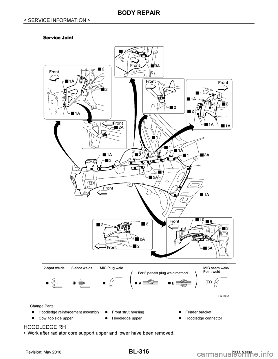
HOODLEDGE RH
• Work after radiator core support upper and lower have been removed.
Change Parts�z Hoodledge reinforcement assembly �zFront strut housing �zFender bracket
�z Cowl top side upper �zHoodledge upper �zHoodledge connector
LIIA2893E
Revision: May 2010 2011 Versa
Page 827 of 3787

BODY REPAIRBL-317
< SERVICE INFORMATION >
C
DE
F
G H
J
K L
M A
B
BL
N
O P
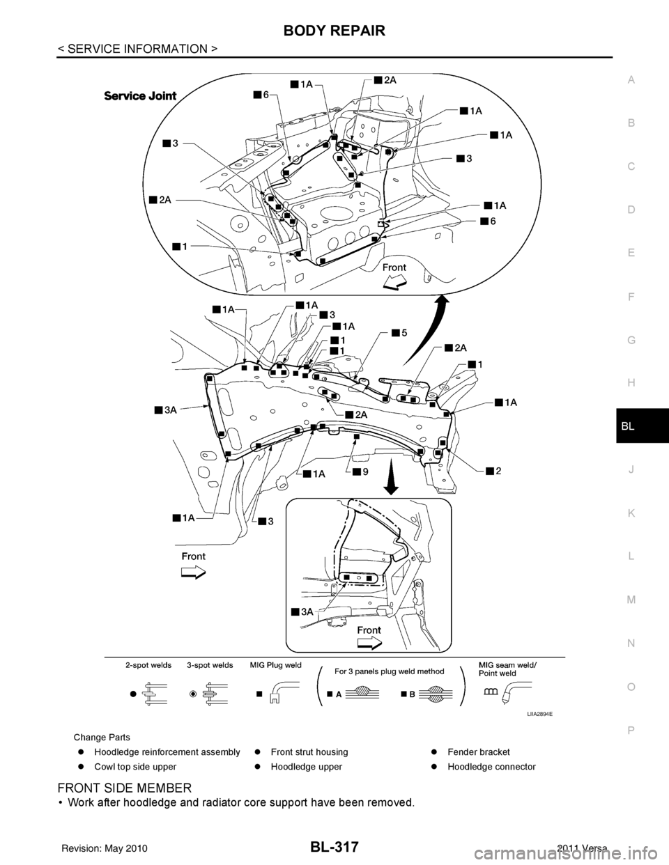
FRONT SIDE MEMBER
• Work after hoodledge and radiator core support have been removed.
Change Parts �z Hoodledge reinforcement assembly �zFront strut housing �zFender bracket
�z Cowl top side upper �zHoodledge upper �zHoodledge connector
LIIA2894E
Revision: May 2010 2011 Versa
Page 908 of 3787
![NISSAN TIIDA 2011 Service Repair Manual TROUBLE DIAGNOSISBRC-19
< SERVICE INFORMATION > [ABS]
C
D
E
G H
I
J
K L
M A
B
BRC
N
O P
Note 1: Confirm tire pressure is normal.
Note 2: ON/OFF timing of ABS warning lamp
ON: For approximately 2 secon NISSAN TIIDA 2011 Service Repair Manual TROUBLE DIAGNOSISBRC-19
< SERVICE INFORMATION > [ABS]
C
D
E
G H
I
J
K L
M A
B
BRC
N
O P
Note 1: Confirm tire pressure is normal.
Note 2: ON/OFF timing of ABS warning lamp
ON: For approximately 2 secon](/manual-img/5/57396/w960_57396-907.png)
TROUBLE DIAGNOSISBRC-19
< SERVICE INFORMATION > [ABS]
C
D
E
G H
I
J
K L
M A
B
BRC
N
O P
Note 1: Confirm tire pressure is normal.
Note 2: ON/OFF timing of ABS warning lamp
ON: For approximately 2 seconds after ignition switch is turned ON, or when a malfunction is detected.
OFF: Approximately 2 seconds after ignition switch is turned ON (when system is in normal operation).
CONSULT-III Function (ABS)INFOID:0000000005928445
CONSULT-III can display each diagnostic item using the diagnostic test modes shown following.
Monitor item Display content Data monitor
Note: Error inspection
checklist
Condition Reference value in
normal operation
FR RH SENSOR
FR LH SENSOR
RR RH SENSOR
RR LH SENSOR Wheel speedVehicle stopped
0 [km/h (MPH)]
BRC-25, "
Wheel Sensor
System"Vehicle running (Note 1) Almost in accor-
dance with speed-
ometer display
(within
±10%)
BATTERY VOLT Battery voltage sup-
plied to ABS actuator
and electric unit (con-
trol unit)Ignition switch ON
10 to 16VBRC-28, "
ABS Control
Unit Power and Ground
Systems Inspection"
STOP LAMP SW
Stop lamp switch oper-
ationBrake pedal depressed ON
—
Brake pedal not depressed OFF
ABS WARN LAMP ABS warning lamp ON
condition (Note 2)ABS warning lamp ON ON
BRC-17, "
Basic Inspec-
tion"ABS warning lamp OFF OFF
MOTOR RELAY Operation status of mo-
tor and motor relayIgnition switch ON or running
(ABS not activated)
OFF
BRC-27, "
Actuator Motor,
Motor Relay, and Circuit
Inspection"Ignition switch ON or engine
running (ABS activated) ON
ACTUATOR RLY Actuator relay opera-
tion statusVehicle stopped (Ignition
switch ON)
OFF
BRC-27, "
Actuator Motor,
Motor Relay, and Circuit
Inspection"Vehicle stopped (Engine run-
ning) ON
FR LH IN SOL
FR LH OUT SOL
FR RH IN SOL
FR RH OUT SOL
RR RH IN SOL
RR RH OUT SOL
RR LH IN SOL
RR LH OUT SOL Solenoid valve opera-
tionActuator (solenoid) is active
(“ACTIVE TEST” with CON-
SULT-III) or actuator relay is in-
active (in fail-safe mode).
ON
BRC-26, "
Solenoid Valve
System Inspection"When actuator (solenoid) is not
active and actuator relay is ac-
tive (ignition switch ON). OFF
ABS SIGNAL
EBD SIGNAL Signal statusABS active
EBD active
ON
ABS system
EBD system
ABS not active
EBD not active OFF
ABS FAIL SIG
EBD FAIL SIG Fail signal statusABS fail
EBD fail
ON
ABS system
EBD system
ABS normal
EBD normal OFF
Diagnostic mode
Description
SELF DIAGNOSTIC RESULT Displays ABS actuator and electric unit (control unit) self-diagnosis results. DATA MONITOR Displays ABS actuator and electric unit (control unit) input/output data in real time.
CAN DIAG SUPPORT MNTR The result of transmit/receive diagnosis of CAN communication can be read. ACTIVE TEST Operation of electrical loads can be checked by sending drive signal to them.
Revision: May 2010 2011 Versa
Page 949 of 3787
![NISSAN TIIDA 2011 Service Repair Manual BRC-60
< SERVICE INFORMATION >[VDC/TCS/ABS]
TROUBLE DIAGNOSIS
Note 1: Confirm tire pressure is normal.
Note 2: On and Off timing for warning lamp and indicator lamp.
CONSULT-III Function (ABS)INFOID:0 NISSAN TIIDA 2011 Service Repair Manual BRC-60
< SERVICE INFORMATION >[VDC/TCS/ABS]
TROUBLE DIAGNOSIS
Note 1: Confirm tire pressure is normal.
Note 2: On and Off timing for warning lamp and indicator lamp.
CONSULT-III Function (ABS)INFOID:0](/manual-img/5/57396/w960_57396-948.png)
BRC-60
< SERVICE INFORMATION >[VDC/TCS/ABS]
TROUBLE DIAGNOSIS
Note 1: Confirm tire pressure is normal.
Note 2: On and Off timing for warning lamp and indicator lamp.
CONSULT-III Function (ABS)INFOID:0000000005928483
CONSULT-III can display each diagnostic item us
ing the diagnostic test modes shown following.
SELF-DIAGNOSIS
Description
If an error is detected in the system, the ABS warning lamp will turn on. In this case, perform self-diagnosis as
follows:
Operation Procedure
1. Turn ignition switch OFF.
2. Connect CONSULT-III To the data link connector.
3. Turn ignition switch ON.
4. Start engine and drive at approximately 30 km/h (19 MPH) for approximately 1 minute.
5. After stopping the vehicle, with the engine running, t ouch “ABS”, “SELF-DIAG RESULTS” in order on the
CONSULT-III screen.
USV[FL-RR]
USV[FR-RL]
HSV[FL-RR]
HSV[FR-RL] VDC switch-over valve
statusWhen actuator (switch-over
valve) is active (“ACTIVE
TEST” with CONSULT-III) or
actuator relay is inactive (when
in fail-safe mode).
On
BRC-72, "
Solenoid and
VDC Change-Over Valve
System Inspection"
When actuator (switch-over
valve) is not active and actua-
tor relay is active (ignition
switch ON). Off
V/R OUTPUT Solenoid valve relay
activatedWhen solenoid valve relay is
active (ignition switch OFF)
On
When solenoid valve relay is
not active (in fail-safe mode) Off
M/R OUTPUT Actuator motor and mo-
tor relay activatedWhen actuator motor and mo-
tor relay are active (“ACTIVE
TEST” with CONSULT-III)
On
BRC-73, "
Actuator Motor,
Motor Relay, and Circuit
Inspection"When actuator motor and mo-
tor relay are inactive Off
ENGINE RPM With engine running With engine stopped
0 rpm
BRC-68, "
Engine System
Inspection"Engine running Almost in accor-
dance with ta-
chometer display
Monitor item
Display content Data monitor
Note: Error inspection
checklist
Condition Reference value in
normal operation
ABS diagnostic mo de Description
WORK SUPPORT Supports inspection and adjustment
s. Commands are transmitted to the ABS actuator and electric unit
(control unit) for setting the status suitable for required operation, input/output signals are received from
the ABS actuator and electric unit (control unit) and received data is displayed.
SELF DIAGNOSTIC RESULT Displays ABS ac tuator and electric unit (control unit) self-diagnosis results.
DATA MONITOR Displays ABS actuator and electric unit (control unit) input/output data in real time.
CAN DIAG SUPPORT MNTR The result of transmit/receive diagnosis of CAN communication can be read. ACTIVE TEST Operation of electrical loads can be checked by sending drive signal to them.
FUNCTION TEST Conducted by CONS ULT-III instead of a technician to determine whether each system is "OK" or "NG".
ECU IDENTIFICATION ABS actuator and electric unit (control unit) part number can be read.
Revision: May 2010 2011 Versa