2011 NISSAN TIIDA Top support
[x] Cancel search: Top supportPage 3535 of 3787

RF-12
< FUNCTION DIAGNOSIS >
TROUBLE DIAGNOSIS
• to sunroof motor assembly terminal 1
• through sunroof switch terminal 3
• through sunroof switch terminal 2
• through grounds M57 and M61.
Then the sunroof will tilt up/slide closed.
TILT DOWN/SLIDE OPEN OPERATION
When down/open switch is pressed, ground is supplied
• to sunroof motor assembly terminal 5
• through sunroof switch terminal 1
• through sunroof switch terminal 2
• through grounds M57 and M61.
Then the sunroof will tilt down/slide open.
AUTO OPERATION
The power sunroof AUTO feature makes it possible to slide open and slide closed or tilt up and tilt down the
sunroof without holding the sunroof switch in the UP/CLOSE or DOWN/OPEN position.
RETAINED POWER OPERATION
When the ignition switch is turned to OFF position from ON position, power is supplied for 45 seconds
• through BCM terminal 68
• to sunroof motor assembly terminal 9.
When power is supplied, the sunroof can be operated.
The retained power operation is canceled when the front door LH or RH is opened.
RAP signal period can be changed by CONSULT-III. Refer to RF-17, "
Work Support" .
ANTI-PINCH FUNCTION
The CPU (central processing unit) of sunroof motor as sembly monitors the sunroof motor operation and the
sunroof position (fully-closed or other ) by the signals from sunroof motor.
When sunroof motor detects an interruption during the following slide close and tilt down operation, sunroof
switch controls the motor for open and the sunroof will oper ate until it reaches full up position (during tilt down
operation) or 125 mm (4.92 in) or more in an open direction (during slide close operation).
• close operation and tilt down when igniti on switch is in the ON position.
• close operation and tilt down during retained power operation.
INITIALIZATION FAILURE CONDITIONS
Initialization and teaching of system should be conducted if the following conditions exist:
• sunroof will only move in the UP/CLOSE direction, having a step by step motion
• sunroof does not have any auto operation.
INITIALIZATION PROCEDURE
If the sunroof does not open or close automatically, use the following procedure to return sunroof operation to
normal.
NOTE:
If the sunroof switch is released at any time during step 3, the procedure must be started over again. Leave
the ignition switch ON for at least 2 seconds after this procedure.
1. Push the ignition switch to the ON position.
2. Hold the sunroof switch in the tilt up position. Release the switch when the s unroof has reached the full tilt
up position.
3. Within 5 seconds of releasing the switch in step 2, hold the sunroof switch in the tilt up position again. The sunroof will move from the open position and back to t he close position. Release the switch only when
the sunroof has reached the full closed position.
RE-TEACHING CONDITIONS
Re-teaching of system should be conducted if any of the following conditions exist:
• the sunroof is manually operated using the sunroof wrench with the battery discharged or disconnected.
• the sunroof is manually operated using the sunroof wrench with the key switch in the OFF position and
retained power timed out (after approximat ely 45 seconds or with a front door open).
• the sunroof motor assembly is replaced with a new one.
• the sunroof motor is removed from the sunroof assembly and operated before it is reinstalled.
• the sunroof motor is removed from the sunroof assembly and the glass panel position is changed.
RE-TEACHING PROCEDURE
1. Using the UP/CLOSE switch, move the sunroof toward the tilt position until it stops.
Revision: May 2010 2011 Versa
Page 3540 of 3787
TROUBLE DIAGNOSISRF-17
< FUNCTION DIAGNOSIS >
C
DE
F
G H
J
K L
M A
B
RF
N
O P
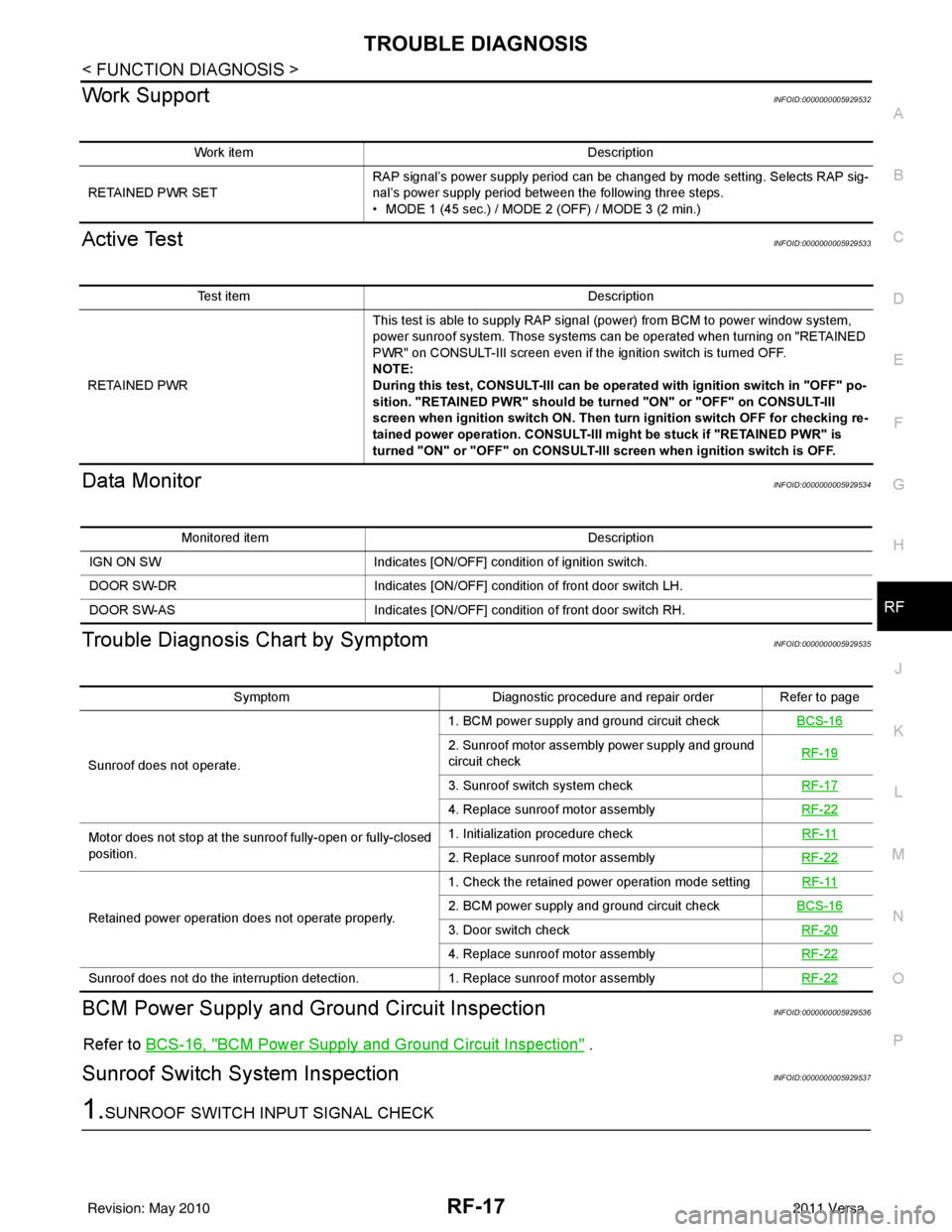
Work SupportINFOID:0000000005929532
Active TestINFOID:0000000005929533
Data MonitorINFOID:0000000005929534
Trouble Diagnosis Chart by SymptomINFOID:0000000005929535
BCM Power Supply and Gr ound Circuit InspectionINFOID:0000000005929536
Refer to BCS-16, "BCM Power Supply and Ground Circuit Inspection" .
Sunroof Switch System InspectionINFOID:0000000005929537
1.SUNROOF SWITCH INPUT SIGNAL CHECK
Work item Description
RETAINED PWR SET RAP signal’s power supply period can be changed by mode setting. Selects RAP sig-
nal’s power supply period between the following three steps.
• MODE 1 (45 sec.) / MODE 2 (OFF) / MODE 3 (2 min.)
Test item
Description
RETAINED PWR This test is able to supply RAP signal (power) from BCM to power window system,
power sunroof system. Those systems can be operated when turning on "RETAINED
PWR" on CONSULT-III screen even if the ignition switch is turned OFF.
NOTE:
During this test, CONSULT-III can be operated with ignition switch in "OFF" po-
sition. "RETAINED PWR" should be turned "ON" or "OFF" on CONSULT-III
screen when ignition switch ON. Then turn ignition switch OFF for checking re-
tained power operation. CONSULT-III might be stuck if "RETAINED PWR" is
turned "ON" or "OFF" on CONSULT-III screen when ignition switch is OFF.
Monitored item
Description
IGN ON SW Indicates [ON/OFF] condition of ignition switch.
DOOR SW-DR Indicates [ON/OFF] condition of front door switch LH.
DOOR SW-AS Indicates [ON/OFF] condition of front door switch RH.
SymptomDiagnostic procedure and repair order Refer to page
Sunroof does not operate. 1. BCM power supply and ground circuit check
BCS-16
2. Sunroof motor assembly power supply and ground
circuit check RF-19
3. Sunroof switch system check
RF-17
4. Replace sunroof motor assemblyRF-22
Motor does not stop at the sunroof fully-open or fully-closed
position. 1. Initialization procedure check
RF-11
2. Replace sunroof motor assemblyRF-22
Retained power operation does not operate properly. 1. Check the retained power operation mode setting
RF-112. BCM power supply and ground circuit checkBCS-16
3. Door switch check RF-20
4. Replace sunroof motor assemblyRF-22
Sunroof does not do the interruption detection. 1. Replace sunroof motor assemblyRF-22
Revision: May 2010 2011 Versa
Page 3695 of 3787
![NISSAN TIIDA 2011 Service Repair Manual STC-8
< SYSTEM DESCRIPTION >[EPS]
DIAGNOSIS SYSTEM (EPS CONTROL UNIT)
DIAGNOSIS SYSTEM
(EPS CONTROL UNIT)
CONSULT-III FunctionINFOID:0000000005931228
FUNCTION
CONSULT-III can display each diagnostic](/manual-img/5/57396/w960_57396-3694.png "NISSAN TIIDA 2011 Service Repair Manual STC-8
< SYSTEM DESCRIPTION >[EPS]
DIAGNOSIS SYSTEM (EPS CONTROL UNIT)
DIAGNOSIS SYSTEM
(EPS CONTROL UNIT)
CONSULT-III FunctionINFOID:0000000005931228
FUNCTION
CONSULT-III can display each diagnostic")
STC-8
< SYSTEM DESCRIPTION >[EPS]
DIAGNOSIS SYSTEM (EPS CONTROL UNIT)
DIAGNOSIS SYSTEM
(EPS CONTROL UNIT)
CONSULT-III FunctionINFOID:0000000005931228
FUNCTION
CONSULT-III can display each diagnostic item us ing the diagnostic test modes shown following.
ECU IDENTIFICATION
Displays the part number stored in the control unit.
SELF-DIAG RESULTS MODE
Display Item List
Refer to STC-24, "DTC Index".
CAUTION:
If “CAN COMM CIRCUIT [U1000]” is disp layed with other DTCs, first perform the trouble diagnosis for
CAN communication line.
DATA MONITOR MODE
Display Item List
*1: Almost in accordance with the value of MOTOR SIG. It is not a malfunction though these values are not accorded when steerin g
quickly.
*2: It is not a malfunction, though it might not be corresponding just after ignition switch in turned ON. Diagnostic test mode
Function
ECU identification Steering column assembly number can be read.
Self diagnostic result Self-diagnostic results can be read and erased quickly.
CAN diag support MNTR The results of transmit/receive diagnosis of CAN communication can be read.
Data monitor Input/Output data in the EPS control unit can be read.
Monitor item (Unit) Remarks
BATTERY VOLT (V) Displays the power supply voltage for EPS control unit.
TORQUE SENSOR (Nm) Displays steering wheel turning force detected by torque sensor.
MOTOR CURRENT (A) Displays the current value consumed by EPS motor.
MOTOR SIG (A)
*1Displays the current commanded value to EPS motor.
VEHICLE SPEED (km/h) or (MPH)
*2Vehicle speed is displayed from vehicle speed signal via CAN communication.
WARNING LAMP (On/Off) EPS warning lamp control status is displayed.
ENGINE STATUS (Stop/Run) Engine speed is displayed from engine status signal via CAN communication.
Revision: May 2010 2011 Versa
Page 3759 of 3787

FRONT WIPER AND WASHER SYSTEMWW-13
< SERVICE INFORMATION >
C
DE
F
G H
I
J
L
M A
B
WW
N
O P
ACTIVE TEST
Display Item List
CONSULT-III Function (IPDM E/R)INFOID:0000000005929216
CONSULT-III can display each diagnostic item using the diagnostic test modes shown following.
DATA MONITOR
All Signals, Main Signals, Selection From Menu
NOTE:
FR WIPER LOW “ON/OFF” Displays “FRONT WIPER LOW (ON)/Other (OFF)” status as judged from combination switch
(wiper switch) signal.
FR WIPER INT “ON/OFF”Displays “FRONT WIPER INT (ON)
/Other (OFF)” status as judged from combination switch
(wiper switch) signal.
FR WASHER SW “ON/OFF” Displays “FRONT WASHER Swit
ch (ON)/Other (OFF)” status as judged from combination
switch (wiper switch) signal.
INT VOLUME “1 - 7”Displays intermittent operation dial position setting (1 - 7) as judged from combination switch
(wiper switch) signal.
FR WIPER STOP “ON/OFF” Displays “Stopped (ON)/Operati ng (OFF)” status as judged from auto-stop signal.
VEHICLE SPEED “km/h” Displays vehicle speed stat us as judged from vehicle speed signal.
RR WIPER ON “ON/OFF”Displays “REAR WIPER (ON)/Other (OFF)” status as judged from combination switch (wiper
switch) signal.
RR WIPER INT “ON/OFF” Displays “REAR WIPER INT (ON)/Other (OFF)” status as judged from combination switch (wip-
er switch) signal.
RR WASHER SW “ON/OFF” Displays “FRONT WASHER Swit
ch (ON)/Other (OFF)” status as judged from combination
switch (wiper switch) signal.
RR WIPER STOP “ON/OFF” Displays “Stopp ed (ON)/Operating (OFF)” status as judged from auto-stop switch 1.
RR WIPER STP2 “ON/OFF” Displays “Stopp ed (ON)/Operating (OFF)” status as judged from auto-stop switch 2.
Monitor item
Contents
Test item Display on CONSULT-III screen Description
Front wiper output FR WIPEROperates front wiper in (INT), (LO), or (HI).
Rear wiper output RR WIPEROperates rear wiper in (ON) or (OFF)
IPDM E/R diagnostic Mode Description
SELF DIAGNOSTIC RESULT Displays IPDM E/R self-diagnosis results.
DATA MONITOR Displays IPDM E/R input/output data in real time.
CAN DIAG SUPPORT MNTR The result of transmit/receive diagnosis of CAN communication can be read. ACTIVE TEST Operation of electrical loads can be checked by sending drive signal to them.
ALL SIGNALS Monitors all items.
MAIN SIGNALS Monitor the predetermined item.
SELECTION FROM MENU Selects items and monitors them.
Item name CONSULT-III
screen display Display or unit Monitor item selection
Description
ALL
SIGNALS MAIN
SIGNALS SELECTION
FROM MENU
FR wiper request FR WIP REQ STOP/1LOW/
LOW/HI×× ×
Signal status input from BCM
Wiper auto stop WIP AUTO STOP ACT P/STOP P ×× ×Output status of IPDM E/R
Wiper protection WIP PROT OFF/BLOCK ×× ×Control status of IPDM E/R
Revision: May 2010 2011 Versa