2011 NISSAN TIIDA Top support
[x] Cancel search: Top supportPage 2473 of 3787
![NISSAN TIIDA 2011 Service Repair Manual ENGINE ASSEMBLYEM-83
< REMOVAL AND INSTALLATION > [HR16DE]
C
D
E
F
G H
I
J
K L
M A
EM
NP
O
• If items or work required are not covered by the engine section, follow the procedures in the applica-
bl](/manual-img/5/57396/w960_57396-2472.png "NISSAN TIIDA 2011 Service Repair Manual ENGINE ASSEMBLYEM-83
< REMOVAL AND INSTALLATION > [HR16DE]
C
D
E
F
G H
I
J
K L
M A
EM
NP
O
• If items or work required are not covered by the engine section, follow the procedures in the applica-
bl")
ENGINE ASSEMBLYEM-83
< REMOVAL AND INSTALLATION > [HR16DE]
C
D
E
F
G H
I
J
K L
M A
EM
NP
O
• If items or work required are not covered by the engine section, follow the procedures in the applica-
ble sections.
• Always use the support poin t specified for lifting.
• Use either 2-pole lift type or separate type lift as best you can. If board-on type is used for unavoid-
able reasons, support at the rear axle jacking point with a transmission jack or similar tool before
starting work, in preparation for the backward shif t of center of gravity.
• For supporting points fo r lifting and jacking point at rear axle, refer to GI-38, "
Garage Jack and
Safety Stand and 2-Pole Lift".
REMOVAL
Outline
Remove the engine and the transaxle assembly from t he vehicle downward. Separate the engine and the tran-
saxle.
Preparation
1. Remove the hood assembly. Refer to BL-14, "Removal and Installation".
2. Remove the cowl top cover and cowl top extension assembly. Refer to EI-24, "
Removal and Installation".
3. Release fuel pressure. Refer to EC-499, "
Inspection".
4. Drain engine coolant from radiator. Refer to CO-11, "
Changing Engine Coolant".
CAUTION:
• Perform this step when the engine is cold.
• Never spill engine coolant on drive belt.
5. Remove the following parts. • Engine under cover. Refer to EI-15, "
Removal and Installation".
• Front road wheels and tires. Refer to WT-7, "
Adjustment".
• Front fender protector (RH and LH). Refer to EI-26, "
Removal and Installation".
• Battery and battery tray. Refer to SC-7, "
Removal and Installation".
• Drive belt. Refer to EM-14, "
Removal and Installation".
• Air duct and air cleaner case assembly. Refer to EM-25, "
Exploded View".
• Radiator hose (upper and lower). Refer to CO-16, "
Component".
• Disconnect cooling fan controller wiring harness.
• Remove coolant reservoir tank.
• Remove fan shroud and cooling fan assembly. Refer to CO-18, "
Component (Models with A/C)" or CO-
18, "Component (Models without A/C)".
Engine Room LH
1. Disconnect all connections of engine harness around the engine mounting insulator (LH), and then tem-
porarily secure the engine harness into the engine side.
CAUTION:
Protect connectors using a resin bag against foreign materials.
2. Remove ground cable at transaxle side.
3. Disconnect fuel feed hose at engine side. Refer to EM-33, "
Exploded View".
4. Disconnect EVAP purge hose and brake booster vacuum hose.
5. Disconnect heater hoses, and install plugs them to prevent engine coolant from draining. Refer to CO-16,
"Component".
6. Disconnect control linkage from transaxle. Refer to AT-213, "
A/T Shift Selector Removal and Installation"
(A/T), MT-14, "Exploded View" (M/T).
7. Disconnect the clutch tube at tr ansmission side (if equipped). Refer to CL-15, "
Removal and Installation".
Engine Room RH
1. Remove ground cable between front cover and vehicle.
2. Remove generator and generator br acket (A/C models). Refer to SC-25, "
Removal and Installation".
3. Remove A/C compressor with piping connected from t he engine. Temporarily secure it on the vehicle side
with a rope to avoid putting load on it (if equipped). Refer to MTC-78, "
Removal and Installation of Com-
pressor - HR16DE".
Vehicle Underbody
1. Remove front wheel sensor (LH and RH) for ABS from steering knuckle (if equipped). Refer to BRC-33,
"Removal and Installation" (ABS) or BRC-86, "Removal and Installation" (VDC/TCS/ABS).
Revision: May 2010 2011 Versa
Page 2475 of 3787
![NISSAN TIIDA 2011 Service Repair Manual ENGINE ASSEMBLYEM-85
< REMOVAL AND INSTALLATION > [HR16DE]
C
D
E
F
G H
I
J
K L
M A
EM
NP
O
4. Remove engine mounting insulator (RH) (1), engine mounting
bracket (RH) (2) and engine mounting stay (3).](/manual-img/5/57396/w960_57396-2474.png "NISSAN TIIDA 2011 Service Repair Manual ENGINE ASSEMBLYEM-85
< REMOVAL AND INSTALLATION > [HR16DE]
C
D
E
F
G H
I
J
K L
M A
EM
NP
O
4. Remove engine mounting insulator (RH) (1), engine mounting
bracket (RH) (2) and engine mounting stay (3).")
ENGINE ASSEMBLYEM-85
< REMOVAL AND INSTALLATION > [HR16DE]
C
D
E
F
G H
I
J
K L
M A
EM
NP
O
4. Remove engine mounting insulator (RH) (1), engine mounting
bracket (RH) (2) and engine mounting stay (3).
5. Remove engine mounting insulator (LH) (4) through bolt secur- ing nut (A).
6. Carefully lower jack, or raise lift to remove the engine and the transaxle assembly. CAUTION:
• Make sure that no part interferes with the vehicle side.
• Before and during this lifting, alw ays check if any harnesses are left connected.
• During the removal, always be careful to prevent the vehicle from falling off the lift due to
changes in the center of gravity.
• If necessary, support the vehicle by setting jack or suitable tool at the rear.
Separation
1. Remove starter motor. Refer to SC-19, "Removal and Installation HR16DE".
2. Lift with a hoist and separate the engine from the transaxle assembly. Refer to EM-82, "
Exploded View".
INSTALLATION
Installation is in the reverse order of removal.
• Do not allow engine oil to get on engine mounting insulator. Be careful not to damage engine mounting insu-
lator.
• Make sure that each mounting insulator is seated properly, and tighten nuts and bolts.
• Tighten engine mounting insulator (RH) bolts in the numerical
order shown.
InspectionINFOID:0000000005930964
INSPECTION AFTER INSTALLATION
• Before starting engine, check oil/fluid levels incl uding engine coolant and engine oil. If less than required
quantity, fill to the specified level. Refer to MA-14, "
Fluids and Lubricants".
• Use procedure below to check for fuel leakage.
• Turn ignition switch ON (with engine stopped). With fuel pressure applied to fuel piping, check for fuel leak-
age at connection points.
• Start engine. With engine speed increased, check again for fuel leakage at connection points.
• Run engine to check for unusual noise and vibration.
• Warm up engine thoroughly to make sure there is no leak age of fuel, exhaust gas, or any oils/fluids including
engine oil and engine coolant.
• Bleed air from passages in lines and hoses, such as in cooling system.
• After cooling down engine, again check oil/fluid levels including engine oil and engine coolant. Refill to spec- ified level, if necessary.
• Summary of the inspection items:
JPBIA0512ZZ
: Vehicle front
JPBIA0280ZZ
Item Before starting engine Engine runningAfter engine stopped
Engine coolant LevelLeakage Level
Revision: May 2010 2011 Versa
Page 2588 of 3787
![NISSAN TIIDA 2011 Service Repair Manual EM-198
< SERVICE INFORMATION >[MR18DE]
ENGINE ASSEMBLY
• Use either 2-pole lift type or separate type lift as
best you can. If board-on type is used for unavoid-
able reasons, support at the rear a](/manual-img/5/57396/w960_57396-2587.png "NISSAN TIIDA 2011 Service Repair Manual EM-198
< SERVICE INFORMATION >[MR18DE]
ENGINE ASSEMBLY
• Use either 2-pole lift type or separate type lift as
best you can. If board-on type is used for unavoid-
able reasons, support at the rear a")
EM-198
< SERVICE INFORMATION >[MR18DE]
ENGINE ASSEMBLY
• Use either 2-pole lift type or separate type lift as
best you can. If board-on type is used for unavoid-
able reasons, support at the rear axle jacking point with a transmission jack or similar tool before
starting work, in preparation for the backward shift of center of gravity.
• For supporting points for lifting and jacking point at rear axle, refer to GI-38, "
Garage Jack and
Safety Stand and 2-Pole Lift".
REMOVAL
Remove the engine and the transaxle assembly from t he vehicle downward. Separate the engine and the tran-
saxle.
1. Remove engine under cover. Refer to EI-15, "
Removal and Installation".
2. Drain engine coolant from radiator. Refer to CO-36, "
Changing Engine Coolant".
CAUTION:
• Perform this step when the engine is cold.
• Do not spill engine coolant on drive belt.
3. Drain clutch fluid (M/T models). Refer to CL-9, "
Air Bleeding Procedure".
4. Remove front fender protector (RH and LH). Refer to EI-26
.
5. Remove exhaust front tube. Refer to EX-10
.
6. Remove drive shafts (LH and RH) from steering knuckle. Refer to FA X - 9
.
7. Remove transaxle joint bolts which pierce at oil pan (upper) lower rear side. Refer to AT-233
(A/T models),
CVT-180, "
Removal and Installation" (CVT models) or MT-61, "Removal and Installation" (M/T models).
8. Remove rear torque rod (1). NOTE:
A/T model shown CVT and M/T models similar.
9. Remove hood assembly. Refer to BL-13
.
10. Remove cowl top cover and cowl top extension assembly. Refer to EI-24
.
11. Release fuel pressure. Refer to EC-582, "
Fuel Pressure Check".
12. Remove battery and battery tray. Refer to SC-5
.
13. Remove drive belt; Refer to EM-132, "
Component".
14. Remove engine room cover.
15. Remove air duct and air cleaner case assembly. Refer to EM-135
.
16. Remove cooling fan assembly. Refer to CO-44, "
Removal and Installation".
17. Remove radiator hose (upper and lower). Refer to CO-40
.
18. Disconnect A/T fluid cooler hoses or CVT water hoses. Refer to CO-40, "
Component" (A/T) or CVT-175,
"WATER HOSE : Exploded View" (CVT).
NOTE:
Cap or plug opening(s) to prevent fluid from spilling.
19. Disconnect all connections of engine harness around the engine mounting insulator (LH), and then tem- porarily secure the engine harness into the engine side.
CAUTION:
Protect connectors using a resin bag to protect against foreign materials during the operation.
20. Disconnect fuel feed hose at engine side. Refer to EM-154, "
Component".
NOTE:
Cap or plug opening(s) to revent fluid from spilling.
21. Disconnect heater hoses. Refer to CO-50, "
Component".
NOTE:
Cap or plug opening(s) to revent fluid from spilling.
LBIA0460E
Revision: May 2010 2011 Versa
Page 2593 of 3787
![NISSAN TIIDA 2011 Service Repair Manual CYLINDER BLOCKEM-203
< SERVICE INFORMATION > [MR18DE]
C
D
E
F
G H
I
J
K L
M A
EM
NP
O
Disassembly and AssemblyINFOID:0000000005931033
DISASSEMBLY
1. Remove engine and transaxle assembly from vehicle,](/manual-img/5/57396/w960_57396-2592.png "NISSAN TIIDA 2011 Service Repair Manual CYLINDER BLOCKEM-203
< SERVICE INFORMATION > [MR18DE]
C
D
E
F
G H
I
J
K L
M A
EM
NP
O
Disassembly and AssemblyINFOID:0000000005931033
DISASSEMBLY
1. Remove engine and transaxle assembly from vehicle,")
CYLINDER BLOCKEM-203
< SERVICE INFORMATION > [MR18DE]
C
D
E
F
G H
I
J
K L
M A
EM
NP
O
Disassembly and AssemblyINFOID:0000000005931033
DISASSEMBLY
1. Remove engine and transaxle assembly from vehicle, separate transaxle from engine. Refer to
EM-197.
2. Install engine to engine stand as follows;
a. Remove flywheel (M/T models) or drive plate (1) (A/T or CVT models).
• Secure flywheel (M/T models) or drive plate (A/T or CVT mod-els) using Tool (A), and remove bolts.
CAUTION:
Be careful not to damage or scratch drive plate (A/T or CVT
models) and contact surface for clutch disc of flywheel (M/T
models).
NOTE:
Figure shows drive plate (1) (A/T or CVT models)
b. Lift the engine with a hoist to install it onto widely use engine stand. CAUTION:
• Use the engine stand that has a load capacity [approximately 135 kg (298 lb) or more] large
enough for supporting the engine weight.
• If the load capacity of stand is not adequate, remove the following parts beforehand to reduce the poten-
tial risk of overturning stand.
- Exhaust manifold; Refer to EM-141
.
- Rocker cover; Refer to EM-151
.
NOTE:
The figure shows an example of widely used engine stand (A)
that can support mating surface of transaxle with flywheel (M/T
models) or drive plate (A/T or CVT models) removed.
CAUTION:
Before removing the hanging chains, make sure the engine
stand is stable and there is no risk of overturning.
3. Remove oil pan (upper and lower). Refer to EM-144
.
4. Remove cylinder head. Refer to EM-186
.
5. Remove thermostat housing. Refer to CO-47
.
6. Remove knock sensor. CAUTION:
Carefully handle knock sensor avoiding shocks.
7. Remove crankshaft position sensor (POS) cover and crankshaft position sensor (POS).
7. Oil pressure switch 8. Top ring 9. Second ring
10. Oil ring 11. Snap ring 12. Piston
13. Piston pin 14. Connecting rod 15. Thrust bearing
16. Connecting rod bearing upper 17. Main bearing upper 18. Crankshaft key
19. Main bearing lower 20. Connecting rod bearing lower 21. Connecting rod bearing cap
22. Connecting rod bolt 23. Main bearing cap 24. Main bearing cap bolt
25. Crankshaft 26. Pilot converter (A/T or CVT models) 27. Signal plate
28. Rear oil seal 29. Drive plate (A/T or CVT models) 30. Reinforcement plate (A/T or CVT
models)
31. Flywheel (M/T models) 32. Block heater (Canada only) A. Refer to EM-203
Tool number : KV 11105210 (J-44716)
PBIC3226J
PBIC3227J
Revision: May 2010 2011 Versa
Page 2707 of 3787
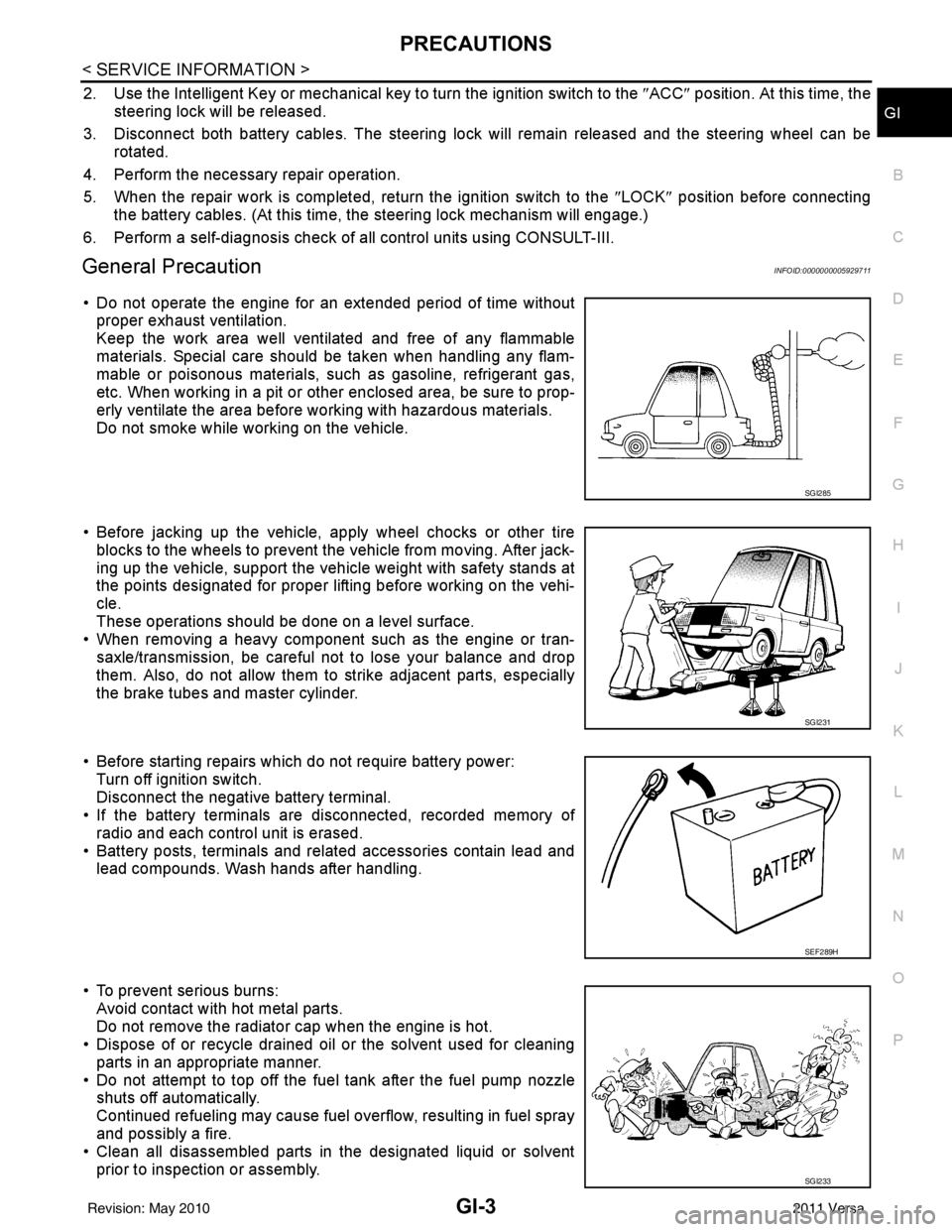
PRECAUTIONSGI-3
< SERVICE INFORMATION >
C
DE
F
G H
I
J
K L
M B
GI
N
O P
2. Use the Intelligent Key or mechanical key to turn the ignition switch to the ″ACC ″ position. At this time, the
steering lock will be released.
3. Disconnect both battery cables. The steering lock will remain released and the steering wheel can be
rotated.
4. Perform the necessary repair operation.
5. When the repair work is completed, return the ignition switch to the ″LOCK ″ position before connecting
the battery cables. (At this time, the steering lock mechanism will engage.)
6. Perform a self-diagnosis check of al l control units using CONSULT-III.
General PrecautionINFOID:0000000005929711
• Do not operate the engine for an extended period of time without
proper exhaust ventilation.
Keep the work area well ventilated and free of any flammable
materials. Special care should be taken when handling any flam-
mable or poisonous materials, such as gasoline, refrigerant gas,
etc. When working in a pit or ot her enclosed area, be sure to prop-
erly ventilate the area before working with hazardous materials.
Do not smoke while working on the vehicle.
• Before jacking up the vehicle, apply wheel chocks or other tire blocks to the wheels to prevent t he vehicle from moving. After jack-
ing up the vehicle, support the vehicle weight with safety stands at
the points designated for proper lifting before working on the vehi-
cle.
These operations should be done on a level surface.
• When removing a heavy component such as the engine or tran-
saxle/transmission, be careful not to lose your balance and drop
them. Also, do not allow them to strike adjacent parts, especially
the brake tubes and master cylinder.
• Before starting repairs which do not require battery power: Turn off ignition switch.
Disconnect the negative battery terminal.
• If the battery terminals are disconnected, recorded memory of
radio and each control unit is erased.
• Battery posts, terminals and related accessories contain lead and lead compounds. Wash hands after handling.
• To prevent serious burns: Avoid contact with hot metal parts.
Do not remove the radiator cap when the engine is hot.
• Dispose of or recycle drained oil or the solvent used for cleaning
parts in an appropriate manner.
• Do not attempt to top off the fuel tank after the fuel pump nozzle shuts off automatically.
Continued refueling may cause fuel overflow, resulting in fuel spray
and possibly a fire.
• Clean all disassembled parts in the designated liquid or solvent
prior to inspection or assembly.
SGI285
SGI231
SEF289H
SGI233
Revision: May 2010 2011 Versa
Page 3279 of 3787
![NISSAN TIIDA 2011 Service Repair Manual MT-58
< SERVICE INFORMATION >[RS6F94R]
CONTROL LINKAGE
CONTROL LINKAGE
Component of Contro
l Device and CableINFOID:0000000005929693
Removal and InstallationINFOID:0000000005929694
REMOVAL
1. Remove b](/manual-img/5/57396/w960_57396-3278.png "NISSAN TIIDA 2011 Service Repair Manual MT-58
< SERVICE INFORMATION >[RS6F94R]
CONTROL LINKAGE
CONTROL LINKAGE
Component of Contro
l Device and CableINFOID:0000000005929693
Removal and InstallationINFOID:0000000005929694
REMOVAL
1. Remove b")
MT-58
< SERVICE INFORMATION >[RS6F94R]
CONTROL LINKAGE
CONTROL LINKAGE
Component of Contro
l Device and CableINFOID:0000000005929693
Removal and InstallationINFOID:0000000005929694
REMOVAL
1. Remove battery. Refer to SC-7, "Removal and Installation".
2. Remove air duct (front), air duct (Inlet) and air cleaner case. Refer to EM-135, "
Removal and Installation".
3. Remove shift selector cable from control shaft shift lever.
4. Remove select cable according to the following.
a. Move stopper (1) to the unlocked position.
1. Shift selector handle 2. Shift selector3. M/T shift selector assembly
4. Select cable 5. Shift selector cable6. Lock plate
7. Clutch housing 8. Cable bracket9. Tapping bolt
10. Cable support bracket 11. Adapter plate
WCIA0626E
SCIA7842E
Revision: May 2010 2011 Versa
Page 3280 of 3787
![NISSAN TIIDA 2011 Service Repair Manual CONTROL LINKAGEMT-59
< SERVICE INFORMATION > [RS6F94R]
D
E
F
G H
I
J
K L
M A
B
MT
N
O P
b. Pull the release button (1) of select cable (2) and then remove it from control shaft select lever (3).
5. Mo](/manual-img/5/57396/w960_57396-3279.png "NISSAN TIIDA 2011 Service Repair Manual CONTROL LINKAGEMT-59
< SERVICE INFORMATION > [RS6F94R]
D
E
F
G H
I
J
K L
M A
B
MT
N
O P
b. Pull the release button (1) of select cable (2) and then remove it from control shaft select lever (3).
5. Mo")
CONTROL LINKAGEMT-59
< SERVICE INFORMATION > [RS6F94R]
D
E
F
G H
I
J
K L
M A
B
MT
N
O P
b. Pull the release button (1) of select cable (2) and then remove it from control shaft select lever (3).
5. Move shift selector to neutral position.
6. Remove shift selector handle.
7. Remove center console assembly. Refer to IP-12, "
Removal and
Installation".
8. Remove M/T shift selector assembly bolts.
9. Remove exhaust front tube, cent er muffler and heat plate. Refer
to EX-10, "
Removal and Installation".
10. Remove cable support bracket.
11. Remove select cable and shift selector cable from cable bracket.
12. Remove M/T shift selector assembly from the vehicle.
INSTALLATION
Installation is in the reverse order of removal.
NOTE:
Self tapping bolts are used to attach cables to the clutch housing.
• Securely assemble each cable and lever of control shaft.
• Be careful about the installation direction, and push shift selector handle onto shift selector.
CAUTION:
Do not reuse shift selector handle.
• Make sure that the front/rear claws (1) of M/T shift selector assem- bly are in contact with flange of the floor (2).
• When shift selector is selected to 1st-2nd side and 5th-6th side, confirm shift lever returns to neutral position smoothly.
• When shift selector is shifted to each position, make sure there is
no binding or disconnection in each boot.
• Move stopper (1) to lock position when installing the shift cable onto the control shaft shift lever.
WCIA0606E
SCIA7630E
PCIB1510E
SCIA7846E
Revision: May 2010 2011 Versa
Page 3438 of 3787

PG-18
< SERVICE INFORMATION >
IPDM E/R (INTELLIGENT POWER DISTRIBUTION MODULE ENGINE ROOM)
IPDM E/R STATUS CONTROL
In order to save power, IPDM E/R switches status by itself based on each operating condition.
1. CAN communication status • CAN communication is normally performed with other control units.
• Individual unit control by IPDM E/R is normally performed.
• When sleep request signal is received from BCM, mode is switched to sleep waiting status.
2. Sleep waiting status • Process to stop CAN communication is activated.
• All systems controlled by IPDM E/R are stopped. When 1 second has elapsed after CAN communica-tion with other control units is st opped, mode switches to sleep status.
3. Sleep status • IPDM E/R operates in low current-consumption mode.
• CAN communication is stopped.
• When a change in CAN communication signal is detec ted, mode switches to CAN communication sta-
tus.
• When a change in ignition switch signal is detected, mode switches to CAN communication status.
CAN Communication System DescriptionINFOID:0000000005928344
Refer to LAN-7, "System Diagram".
Function of Detecting I gnition Relay MalfunctionINFOID:0000000005928345
• When the integrated ignition relay is stuck in a "closed contact" position and cannot be turned OFF, IPDM E/
R turns ON tail and parking lamps for 10 minutes to indicate IPDM E/R malfunction.
• When the state of the integrated ignition relay does not agree with the state of the ignition switch signal
received via CAN communication, the IPDM E/R activates the tail lamp relay.
NOTE:
When the ignition switch is turned ON, the tail lamps are OFF.
CONSULT-III Function (IPDM E/R)INFOID:0000000005928346
CONSULT-III can display each diagnostic item us ing the diagnostic test modes shown following.
SELF-DIAGNOSTIC RESULTS
Display Item List
Rear window defoggerRear window defogger relay OFF
A/C compressor A/C relay is OFF
Front fog lamps Front fog lamp relay OFF
Controlled system
Fail-safe mode
Ignition switch signalIgnition relay status Tail lamp relay
ON ON —
OFF OFF —
ON OFF —
OFF ON ON (10 minutes)
IPDM E/R diagnostic Mode Description
SELF-DIAG RESULTS Displays IPDM E/R self-diagnosis results. DATA MONITOR Displays IPDM E/R input/output data in real time.
CAN DIAG SUPPORT MNTR The result of transmit/receive diagnosis of CAN communication can be read. ACTIVE TEST Operation of electrical loads can be checked by sending drive signal to them.
Revision: May 2010 2011 Versa