Page 769 of 3787

NATS (NISSAN ANTI-THEFT SYSTEM)BL-259
< SERVICE INFORMATION >
C
DE
F
G H
J
K L
M A
B
BL
N
O P
1.CONFIRM SELF-DIAGNOSTIC RESULTS
Confirm SELF-DIAGNOSTIC RESULTS “CHAIN OF ECM-IMMU” displayed on CONSULT-III screen.
NOTE:
In rare case, “CHAIN OF ECM-IMMU” might be stored during key registration procedure, even if the system is
not malfunctioning.
Is
“CHAIN OF ECM-IMMU” displayed?
Yes >> GO TO 2
No >> GO TO BL-257, "
Trouble Diagnosis" .
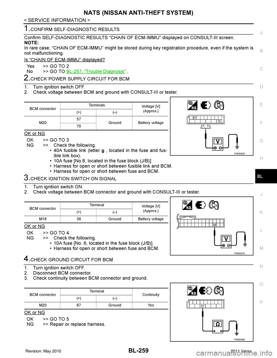
2.CHECK POWER SUPPLY CIRCUIT FOR BCM
1. Turn ignition switch OFF.
2. Check voltage between BCM and ground with CONSULT-III or tester.
OK or NG
OK >> GO TO 3
NG >> Check the following. • 40A fusible link (letter g , located in the fuse and fus-
ible link box).
• 10A fuse [No.8, located in the fuse block (J/B)].
• Harness for open or short between fusible link and BCM.
• Harness for open or short between fuse and BCM.
3.CHECK IGNITION SWITCH ON SIGNAL
1. Turn ignition switch ON.
2. Check voltage between BCM connector and ground with CONSULT-III or tester.
OK or NG
OK >> GO TO 4
NG >> Check the following. • 10A fuse [No. 6, located in the fuse block (J/B)].
• Harness for open or short between fuse and BCM.
4.CHECK GROUND CIRCUIT FOR BCM
1. Turn ignition switch OFF.
2. Disconnect BCM connector.
3. Check continuity between BCM connector and ground.
OK or NG
OK >> GO TO 5
NG >> Repair or replace harness.
BCM connector Te r m i n a l s
Voltage [V]
(Approx.)
(+) (–)
M20 57
Ground Battery voltage
70
PIIB6582E
BCM connector Terminal
Voltage [V]
(Approx.)
(+) (–)
M18 38Ground Battery voltage
PIIB6587E
BCM connector Terminal
Continuity
(+) (–)
M20 67 Ground Yes
PIIB6588E
Revision: May 2010 2011 Versa
Page 772 of 3787

BL-262
< SERVICE INFORMATION >
NATS (NISSAN ANTI-THEFT SYSTEM)
“ID DISCORD IMM-ECM”:
Registered ID of BCM is in discord with that of ECM.
Is
“ID DISCORD IMM-ECM” displayed?
Ye s > > G O T O 2
No >> GO TO BL-257, "
Trouble Diagnosis" .
2.PERFORM INITIALIZATION WITH CONSULT-III
Perform initialization with CONSULT-III. Re-register all NATS ignition key IDs.
For initialization, refer to “CONSULT-III Operation Manual NATS”.
NOTE:
If the initialization is not completed or ma lfunctions, CONSULT-III shows message on the screen.
Can the system be initialized?
Yes >> • Start engine. (END) • (System initialization had not been completed.)
No >> ECM is malfunctioning. • Replace ECM.
• Perform initialization with CONSULT-III
For initialization, refer to “CONSULT-III Operation Manual NATS”
Diagnosis Procedure 4INFOID:0000000005929443
“COMBINATION METER (SECURITY) DOES NOT LIGHT UP”
1.CHECK FUSE
Check 10A fuse [No.13, located in the fuse block (J/B)]
OK or NG
OK >> GO TO 2
NG >> Replace fuse.
2.CHECK COMBINATION METER (SECURITY)
1. Install 10A fuse.
2. Start engine and turn ignition switch OFF.
3. Check if the combination meter (security) lights up.
OK or NG
OK >> Inspection End.
NG >> GO TO 3
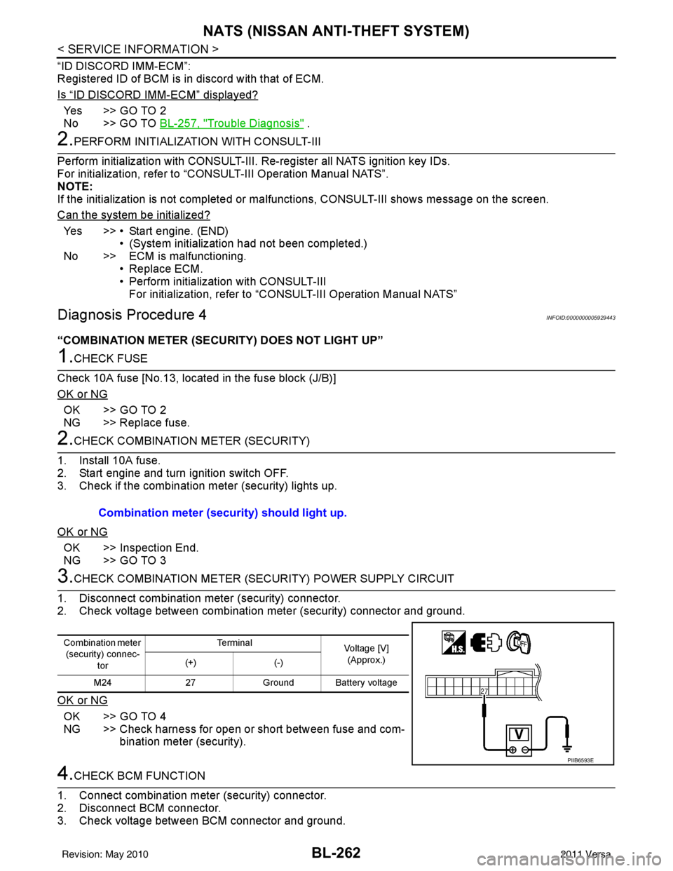
3.CHECK COMBINATION METER (SECURITY) POWER SUPPLY CIRCUIT
1. Disconnect combination meter (security) connector.
2. Check voltage between combination meter (security) connector and ground.
OK or NG
OK >> GO TO 4
NG >> Check harness for open or short between fuse and com- bination meter (security).
4.CHECK BCM FUNCTION
1. Connect combination meter (security) connector.
2. Disconnect BCM connector.
3. Check voltage between BCM connector and ground. Combination meter (security) should light up.
Combination meter
(security) connec-
tor Te r m i n a l
Voltage [V]
(Approx.)
(+) (-)
M24 27Ground Battery voltage
PIIB6593E
Revision: May 2010 2011 Versa
Page 865 of 3787

BR-18
< SERVICE INFORMATION >
BRAKE MASTER CYLINDER
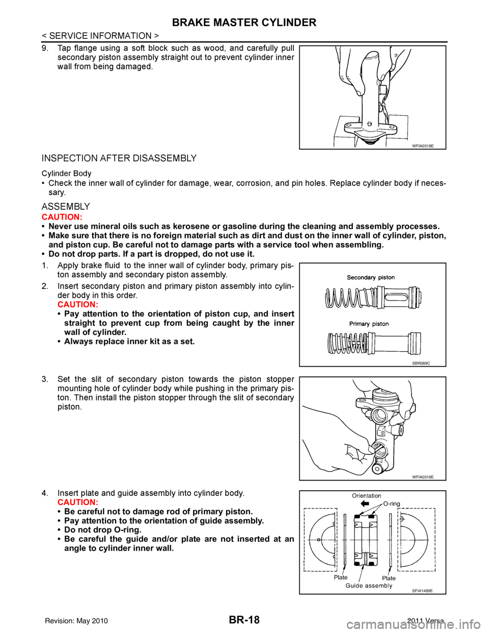
9. Tap flange using a soft block such as wood, and carefully pullsecondary piston assembly straight out to prevent cylinder inner
wall from being damaged.
INSPECTION AFTER DISASSEMBLY
Cylinder Body
• Check the inner wall of cylinder for damage, wear, corrosion, and pin holes. Replace cylinder body if neces-sary.
ASSEMBLY
CAUTION:
• Never use mineral oils such as kerosene or g asoline during the cleaning and assembly processes.
• Make sure that there is no foreign material such as dirt and dust on the inner wall of cylinder, piston,
and piston cup. Be careful not to damage parts with a service tool when assembling.
• Do not drop parts. If a part is dropped, do not use it.
1. Apply brake fluid to the inner wall of cylinder body, primary pis- ton assembly and secondary piston assembly.
2. Insert secondary piston and primary piston assembly into cylin- der body in this order.
CAUTION:
• Pay attention to the orientation of piston cup, and insert
straight to prevent cup from being caught by the inner
wall of cylinder.
• Always replace inner kit as a set.
3. Set the slit of secondary piston towards the piston stopper mounting hole of cylinder body while pushing in the primary pis-
ton. Then install the piston stopper through the slit of secondary
piston.
4. Insert plate and guide assembly into cylinder body. CAUTION:
• Be careful not to damage rod of primary piston.
• Pay attention to the orientation of guide assembly.
• Do not drop O-ring.
• Be careful the guide and/or plate are not inserted at an
angle to cylinder inner wall.
WFIA0518E
SBR089C
WFIA0516E
SFIA1469E
Revision: May 2010 2011 Versa
Page 878 of 3787

FRONT DISC BRAKEBR-31
< SERVICE INFORMATION >
C
DE
G H
I
J
K L
M A
B
BR
N
O P
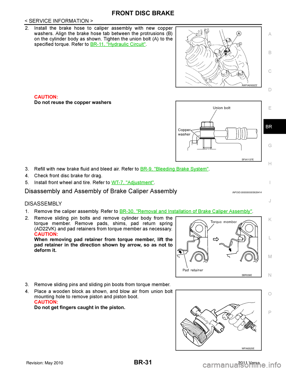
2. Install the brake hose to caliper assembly with new copper washers. Align the brake hose tab between the protrusions (B)
on the cylinder body as shown. Tighten the union bolt (A) to the
specified torque. Refer to BR-11, "
Hydraulic Circuit".
CAUTION:
Do not reuse the copper washers
3. Refill with new brake fluid and bleed air. Refer to BR-9, "
Bleeding Brake System".
4. Check front disc brake for drag.
5. Install front wheel and tire. Refer to WT-7, "
Adjustment".
Disassembly and Assembly of Brake Caliper AssemblyINFOID:0000000005928414
DISASSEMBLY
1. Remove the caliper assembly. Refer to BR-30, "Removal and Installation of Brake Caliper Assembly".
2. Remove sliding pin bolts and remove cylinder body from the torque member. Remove pads, shims, pad return spring
(AD22VK) and pad retainers from torque member as necessary.
CAUTION:
When removing pad retainer from torque member, lift the
pad retainer in the direction shown by arrow, so as not to
deform it.
3. Remove sliding pins and sliding pin boots from torque member.
4. Place a wooden block as shown, and blow air from union bolt mounting hole to remove piston and piston boot.
CAUTION:
Do not get fingers caught in the piston.
AWFIA0502ZZ
SFIA1137E
SBR556E
WFIA0525E
Revision: May 2010 2011 Versa
Page 1008 of 3787
CO-8
< SYMPTOM DIAGNOSIS >[HR16DE]
OVERHEATING CAUSE ANALYSIS
Except cool-
ing system
parts mal-
function—
Overload on engine Abusive driving
High engine rpm under no
load
Driving in low gear for ex-
tended time
Driving at extremely high
speed
Power train system mal-
function
—
Installed improper size
wheels and tires
Dragging brakes
Improper ignition timing
Blocked or restricted air
flow Blocked bumper
Installed front bumper fas-
cia cover
—
Blocked radiator grille Mud contamination or paper
clogging
Blocked radiator Blocked air flow
Blocked condenser
Installed large fog lamp
Symptom
Check items
Revision: May 2010 2011 Versa
Page 1009 of 3787
DESCRIPTIONCO-9
< FUNCTION DIAGNOSIS > [HR16DE]
C
D
E
F
G H
I
J
K L
M A
CO
NP
O
FUNCTION DIAGNOSIS
DESCRIPTION
Engine Cooling SystemINFOID:0000000005930775
AWBIA0155ZZ
1. Cylinder head
2. Cylinder block3. Water pump
4. Thermostat 5. Water inlet6. Water bypass
7. Water outlet A. From radiatorB. To radiator
C. From electric throttle control actuator D. From heater E. To heater
F. To electric throttle control actuator Thermostat openThermostat closed
Revision: May 2010 2011 Versa
Page 1010 of 3787
CO-10
< FUNCTION DIAGNOSIS >[HR16DE]
DESCRIPTION
Engine Cooling System Schematic
INFOID:0000000005930776
AWBIA0784ZZ
1. Reservoir tank 2. Radiator3. Water inlet
4. Thermostat 5. Water bypass6. Water jacket
7. Water pump 8. Cylinder block 9. Cylinder head
10. Water outlet 11. Electric throttle control actuator 12. Heater
A. Thermostat open B. Thermostat closed C. Constant
Revision: May 2010 2011 Versa
Page 1011 of 3787
![NISSAN TIIDA 2011 Service Repair Manual ENGINE COOLANTCO-11
< ON-VEHICLE MAINTENANCE > [HR16DE]
C
D
E
F
G H
I
J
K L
M A
CO
NP
O
ON-VEHICLE MAINTENANCE
ENGINE COOLANT
InspectionINFOID:0000000005930777
LEVEL CHECK
• Check if the reservoir t NISSAN TIIDA 2011 Service Repair Manual ENGINE COOLANTCO-11
< ON-VEHICLE MAINTENANCE > [HR16DE]
C
D
E
F
G H
I
J
K L
M A
CO
NP
O
ON-VEHICLE MAINTENANCE
ENGINE COOLANT
InspectionINFOID:0000000005930777
LEVEL CHECK
• Check if the reservoir t](/manual-img/5/57396/w960_57396-1010.png)
ENGINE COOLANTCO-11
< ON-VEHICLE MAINTENANCE > [HR16DE]
C
D
E
F
G H
I
J
K L
M A
CO
NP
O
ON-VEHICLE MAINTENANCE
ENGINE COOLANT
InspectionINFOID:0000000005930777
LEVEL CHECK
• Check if the reservoir tank engine coolant level is within the “MIN”
to “MAX” range when engine is cool.
• Adjust the engine coolant level as necessary.
CHECKING COOLING SYSTEM FOR LEAKS
To check for leaks, apply pressure to the cooling system using suit-
able tool and Tool.
WARNING:
Never remove the radiator cap wh en the engine is hot. Serious
burns could occur from high pressure coolant escaping from
the radiator.
CAUTION:
Higher pressure than specified may cause radiator damage.
Changing Engine CoolantINFOID:0000000005930778
WARNING:
• To avoid being scalded, do not change engine coolant when engine is hot.
• Wrap a thick cloth around radiator cap and carefully remove the cap. First, turn the cap a quarter of a
turn to release built-up pressure. Then turn the cap all the way.
CAUTION:
• Do not spill engine coolant on drive belt.
DRAINING ENGINE COOLANT
1. Open radiator drain plug (1) at the bottom of radiator, and then remove radiator cap.
• Front
When draining all of engine coolant in the system, open
water drain plug on cylinder block. Refer to EM-90
.
CAUTION:
• Perform this step when engine is cold.
• Do not spill engine coolant on drive belt.
2. Remove reservoir tank as necessary, and drain engi ne coolant and clean reservoir tank before installing.
Refer to CO-16, "
Component".
3. Check drained engine coolant for contaminants such as rust, corrosion or discoloration.
SMA412B
Tool number : EG17650301 (J-33984-A)
Testing pressure : 157 kPa (1.6 kg/cm
2, 23 psi)
WBIA0568E
PBIC3799E
Revision: May 2010 2011 Versa