2011 NISSAN TIIDA washer nozzle
[x] Cancel search: washer nozzlePage 675 of 3787
DOOR
BL-165
< SERVICE INFORMATION >
C
D E
F
G H
J
K L
M A
B
BL
N
O P
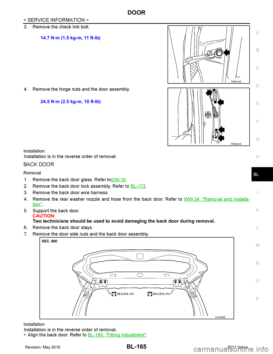
3. Remove the check link bolt.
4. Remove the hinge nuts and the door assembly.
Installation
Installation is in the reverse order of removal.
BACK DOOR
Removal
1. Remove the back door glass. Refer to GW-16.
2. Remove the back door lock assembly. Refer to BL-173
.
3. Remove the back door wire harness.
4. Remove the rear washer nozzle and hose from the back door. Refer to WW-34, "
Removal and Installa-
tion".
5. Support the back door. CAUTION:
Two technicians should be used to avoid damaging the back door during removal.
6. Remove the back door stays.
7. Remove the door side nuts and the back door assembly.
Installation
Installation is in the reverse order of removal.
• Align the back door. Refer to BL-160, "
Fitting Adjustment".
14.7 N·m (1.5 kg-m, 11 ft-lb)
PIIB6543E
24.5 N·m (2.5 kg-m, 18 ft-lb)
PIIB6522E
LIIA2639E
Revision: May 2010
2011 Versa
Page 3747 of 3787
WW-1
ELECTRICAL
C
DE
F
G H
I
J
L
M
SECTION WW
A
B
WW
N
O P
CONTENTS
WIPER, WASHER & HORN
SERVICE INFORMATION .. ..........................2
PRECAUTION ................................................ .....2
Precaution for Supplemental Restraint System
(SRS) "AIR BAG" and "SEAT BELT PRE-TEN-
SIONER" ............................................................. ......
2
Precaution Necessary for Steering Wheel Rota-
tion After Battery Disconnect ............................... ......
2
Precaution for Procedure without Cowl Top Cover ......3
PREPARATION ...................................................4
Special Service Tool ........................................... ......4
FRONT WIPER AND WASHER SYSTEM ..........5
Component Parts and Harness Connector Loca-
tion ...................................................................... ......
5
System Description ...................................................5
CAN Communication System Description .................7
Schematic .................................................................8
Wiring Diagram - WIPER - ........................................9
Terminal and Reference Value for BCM .................12
Terminal and Reference Value for IPDM E/R .........12
How to Proceed with Trouble Diagnosis .................12
Preliminary Check ...................................................12
CONSULT-III Function (BCM) .................................12
CONSULT-III Function (IPDM E/R) .........................13
Front Wiper Does Not Operate ...............................14
Front Wiper Does Not Return to Stop Position (Af-
ter Front Wiper Operates for 10 Seconds, They
Stop for 20 Seconds, and After Repeating the Op-
eration Five Times, They Become Inoperative) ......
16
Only Front Wiper Low Does Not Operate ...............17
Only Front Wiper High Does Not Operate ...............18
Only Front Wiper Intermittent Does Not Operate ....19
Front Wiper Intermittent Operation Switch Posi-
tion Cannot Be Adjusted .........................................
20
Wiper Does Not Wipe When Front Washer Oper-
ates .........................................................................
20
Front Wiper Does Not Stop .....................................20
Removal and Installation of Front Wiper Arms ........20
Adjustment of Wiper Arm Stop Location .............. ....21
Removal and Installation of Front Wiper Drive As-
sembly .....................................................................
22
Removal and Installation of Front Washer Nozzle ....22
Inspection for Washer Nozzle ..................................23
Washer Nozzle Adjustment ................................. ....24
Washer Tube Layout ...............................................24
Removal and Installation of Front Wiper and
Washer Switch .........................................................
25
Inspection of Front Wiper and Washer Switch Cir-
cuit ...........................................................................
25
Removal and Installation of Washer Tank ...............25
Removal and Installation of Front Washer Motor ....26
REAR WIPER AND WASHER SYSTEM ..........27
Component Parts and Harness Connector Loca-
tion ....................................................................... ....
27
System Description ..................................................27
Wiring Diagram - WIP/R - ........................................29
Terminal and Reference Value for BCM ..................31
How to Proceed with Trou ble Diagnosis ..................31
Preliminary Check ............................................... ....31
CONSULT-III Function (BCM) .................................31
Rear Wiper Does Not Operate ............................ ....31
Rear Wiper Stop Position Is Incorrect .....................33
Only Rear Wiper Does Not Operate ........................34
Only Rear Wiper Intermittent Does Not Operate .....34
Wiper Does Not Wipe When Rear Washer Oper-
ates ..........................................................................
34
Removal and Installation .........................................34
Washer Nozzle Adjustment .....................................37
POWER SOCKET .............................................38
Wiring Diagram - P/SCKT - .....................................38
Removal and Installation .........................................38
HORN ................................................................40
Wiring Diagram - HORN - ........................................40
Removal and Installation .........................................40
Revision: May 2010 2011 Versa
Page 3768 of 3787
WW-22
< SERVICE INFORMATION >
FRONT WIPER AND WASHER SYSTEM
Removal and Installation of Front Wiper Drive Assembly
INFOID:0000000005929227
REMOVAL
1. Operate the front wiper motor, and stop at the auto stop position.
2. Remove wiper arms. Refer to WW-20, "
Removal and Installation of Front Wiper Arms" .
3. Remove cowl top cover. Refer to EI-24
.
4. Disconnect wiper motor connector.
5. Remove front wiper drive assembly bolts, and remove front wiper drive assembly.
INSTALLATION
1. Install front wiper drive assembly.
2. Connect wiper motor connector. Turn combination switch (wiper switch) on to operate wiper motor, then turn combination switch (wiper switch) off (auto stop).
3. Install cowl top cover. Refer to EI-24
.
4. Install the wiper arms. Refer to WW-20, "
Removal and Installation of Front Wiper Arms" .
Removal and Installation of Front Washer NozzleINFOID:0000000005929228
REMOVAL
1. Remove cowl top cover. Refer to EI-24, "Removal and Installation" .
2. Remove washer tube.
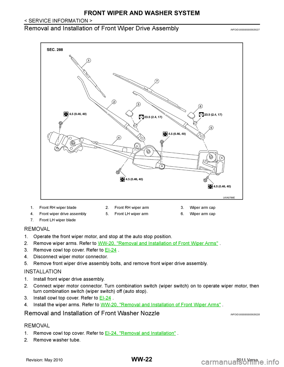
1. Front RH wiper blade 2. Front RH wiper arm 3. Wiper arm cap
4. Front wiper drive assembly 5. Front LH wiper arm 6. Wiper arm cap
7. Front LH wiper blade
LKIA0786E
Revision: May 2010 2011 Versa
Page 3769 of 3787
FRONT WIPER AND WASHER SYSTEMWW-23
< SERVICE INFORMATION >
C
DE
F
G H
I
J
L
M A
B
WW
N
O P
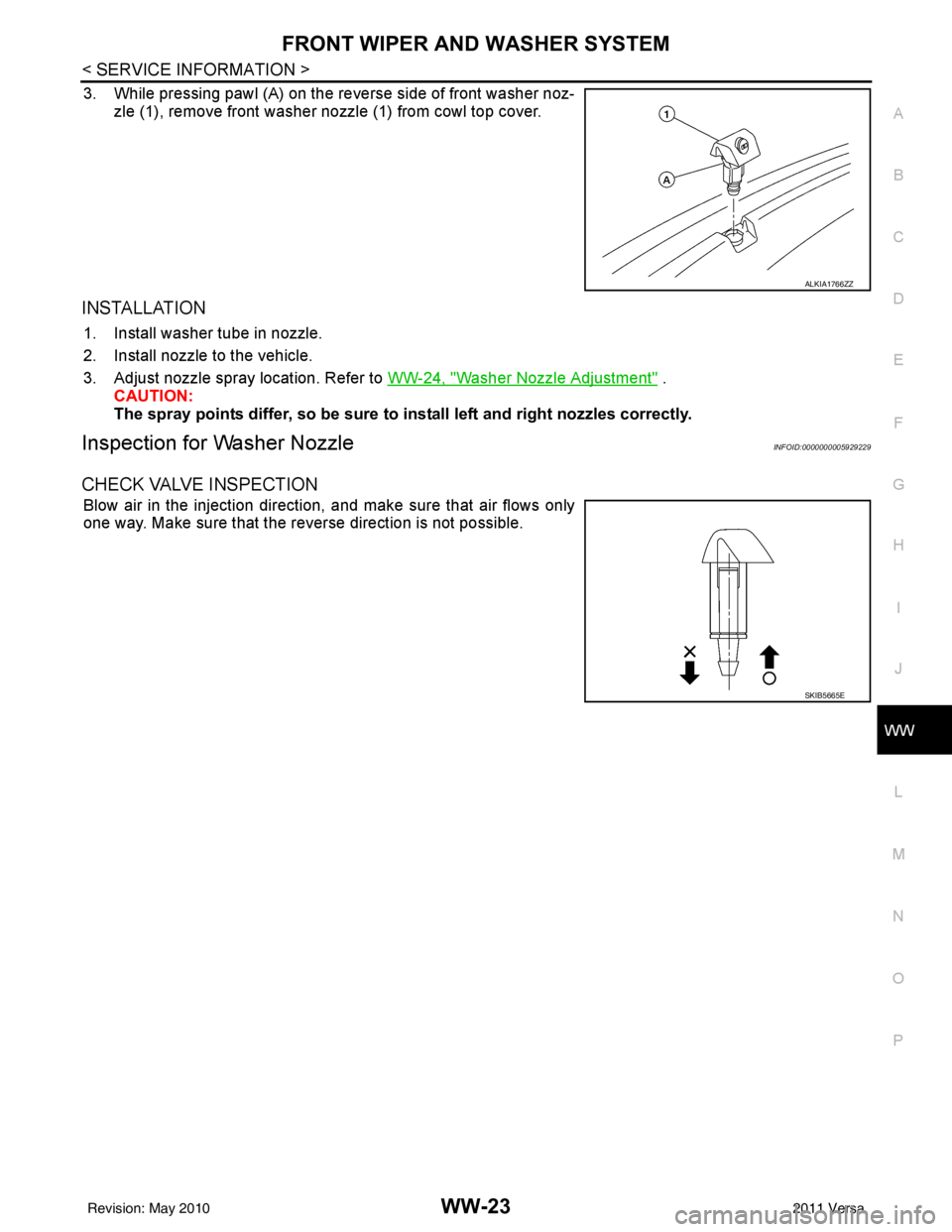
3. While pressing pawl (A) on the reverse side of front washer noz- zle (1), remove front washer nozzle (1) from cowl top cover.
INSTALLATION
1. Install washer tube in nozzle.
2. Install nozzle to the vehicle.
3. Adjust nozzle spray location. Refer to WW-24, "
Washer Nozzle Adjustment" .
CAUTION:
The spray points differ, so be sure to install left and right nozzles correctly.
Inspection for Washer NozzleINFOID:0000000005929229
CHECK VALVE INSPECTION
Blow air in the injection direction, and make sure that air flows only
one way. Make sure that the reverse direction is not possible.
ALKIA1766ZZ
SKIB5665E
Revision: May 2010 2011 Versa
Page 3770 of 3787
WW-24
< SERVICE INFORMATION >
FRONT WIPER AND WASHER SYSTEM
Washer Nozzle Adjustment
INFOID:0000000005929230
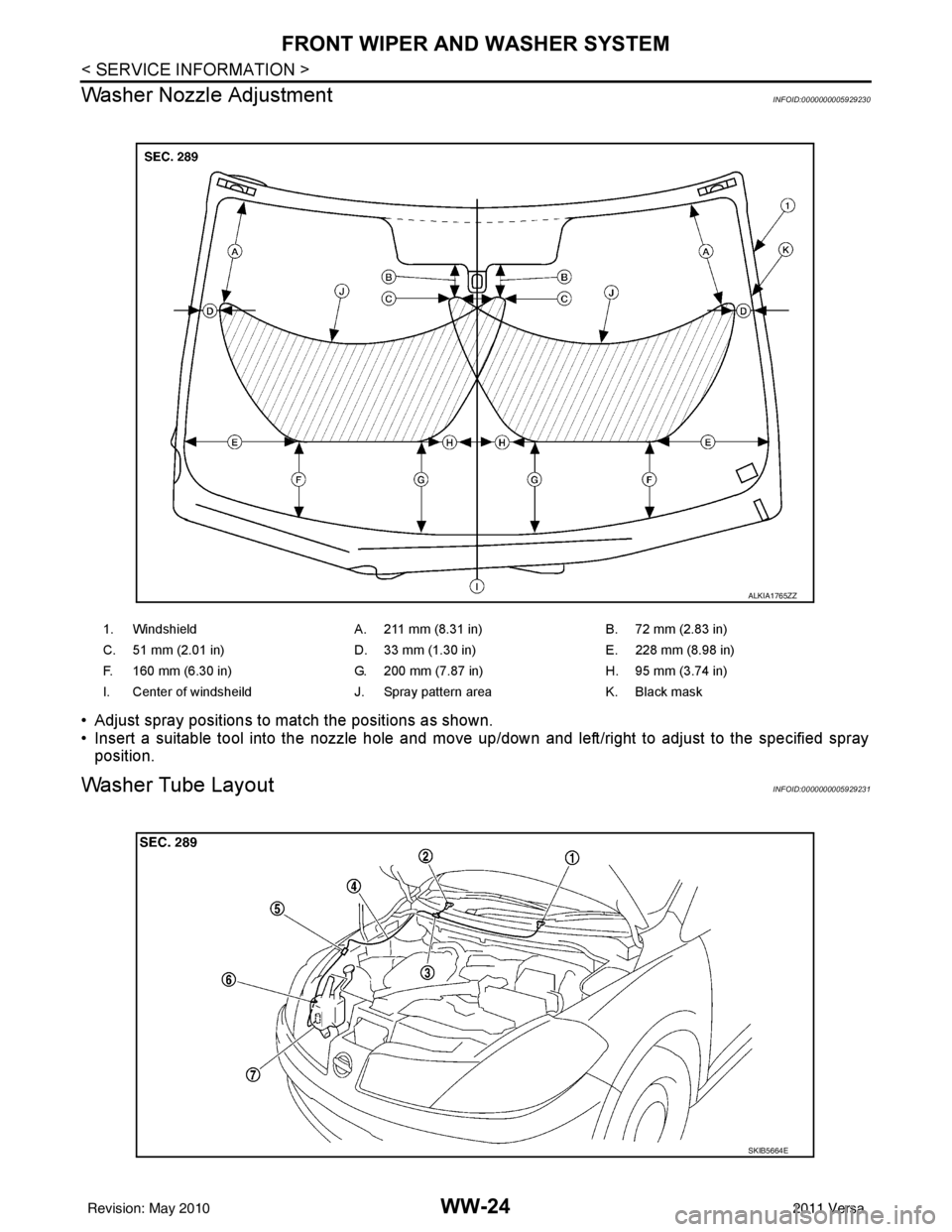
• Adjust spray positions to match the positions as shown.
• Insert a suitable tool into the nozzle hole and move up/down and left/right to adjust to the specified spray position.
Washer Tube LayoutINFOID:0000000005929231
1. Windshield A. 211 mm (8.31 in)B. 72 mm (2.83 in)
C. 51 mm (2.01 in) D. 33 mm (1.30 in)E. 228 mm (8.98 in)
F. 160 mm (6.30 in) G. 200 mm (7.87 in)H. 95 mm (3.74 in)
I. Center of windsheild J. Spray pattern areaK. Black mask
ALKIA1765ZZ
SKIB5664E
Revision: May 2010 2011 Versa
Page 3771 of 3787
FRONT WIPER AND WASHER SYSTEMWW-25
< SERVICE INFORMATION >
C
DE
F
G H
I
J
L
M A
B
WW
N
O P
Removal and Installation of Front Wiper and Washer SwitchINFOID:0000000005929232
REMOVAL
1. Remove the steering column cover. Refer to IP-11 .
2. Disconnect the wiper and washer switch connector.
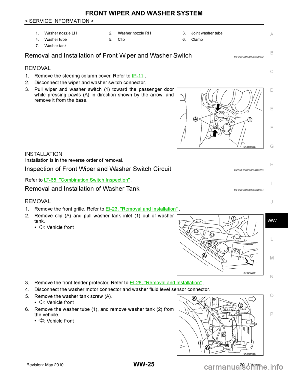
3. Pull wiper and washer switch (1) toward the passenger door while pressing pawls (A) in direction shown by the arrow, and
remove it from the base.
INSTALLATION
Installation is in the reverse order of removal.
Inspection of Front Wiper and Washer Switch CircuitINFOID:0000000005929233
Refer to LT-65, "Combination Switch Inspection" .
Removal and Installation of Washer TankINFOID:0000000005929234
REMOVAL
1. Remove the front grille. Refer to EI-23, "Removal and Installation" .
2. Remove clip (A) and pull washer tank inlet (1) out of washer tank.
• : Vehicle front
3. Remove the front fender protector. Refer to EI-26, "
Removal and Installation" .
4. Disconnect the washer motor connector and washer fluid level sensor connector.
5. Remove the washer tank screw (A). • : Vehicle front
6. Remove the washer tube (1), and remove washer tank (2) from the vehicle.
• : Vehicle front
1. Washer nozzle LH 2. Washer nozzle RH 3. Joint washer tube
4. Washer tube 5. Clip 6. Clamp
7. Washer tank
SKIB5666E
SKIB5667E
SKIB5668E
Revision: May 2010 2011 Versa
Page 3782 of 3787
WW-36
< SERVICE INFORMATION >
REAR WIPER AND WASHER SYSTEM
Removal
1. Remove wiper arm. Refer to "REAR WIPER ARM" .
2. Raise arm cap.
3. Remove the rear wiper motor nut, remove the rear wiper arm and blade.
4. Remove the back door lower finisher. Refer to EI-40, "
Removal and Installation" .
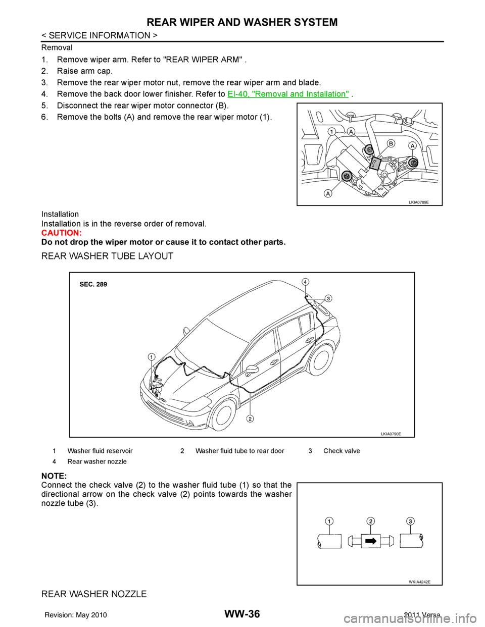
5. Disconnect the rear wiper motor connector (B).
6. Remove the bolts (A) and remove the rear wiper motor (1).
Installation
Installation is in the reverse order of removal.
CAUTION:
Do not drop the wiper motor or cause it to contact other parts.
REAR WASHER TUBE LAYOUT
NOTE:
Connect the check valve (2) to the washer fluid tube (1) so that the
directional arrow on the check valve (2) points towards the washer
nozzle tube (3).
REAR WASHER NOZZLE
LKIA0789E
1 Washer fluid reservoir 2 Washer fluid tube to rear door 3 Check valve
4 Rear washer nozzle
LKIA0790E
WKIA4242E
Revision: May 2010 2011 Versa
Page 3783 of 3787
REAR WIPER AND WASHER SYSTEMWW-37
< SERVICE INFORMATION >
C
DE
F
G H
I
J
L
M A
B
WW
N
O P
Removal
1. Remove the back door side garnish. Refer to
EI-40, "Removal and Installation" .
2. Disconnect rear washer tube from rear washer nozzle.
3. Release retaining clips and remove washer nozzle.
Installation
Installation is in the reverse order of removal.
NOTE:
• Do not pinch the rear washer tube when installing the back door side garnish.
• Inspect rear washer nozzle for proper spray pattern, adjust as necessary. Refer to WW-37, "
Washer Nozzle
Adjustment".
WASHER FLUID RESERVOIR
Refer to WW-25, "Removal and Installation of Washer Tank" .
WIPER AND WASHER SWITCH
Refer to WW-25, "Removal and Installation of Front Wiper and Washer Switch" .
WASHER MOTOR
Refer to WW-26, "Removal and Installation of Front Washer Motor" .
Washer Nozzle AdjustmentINFOID:0000000005929249
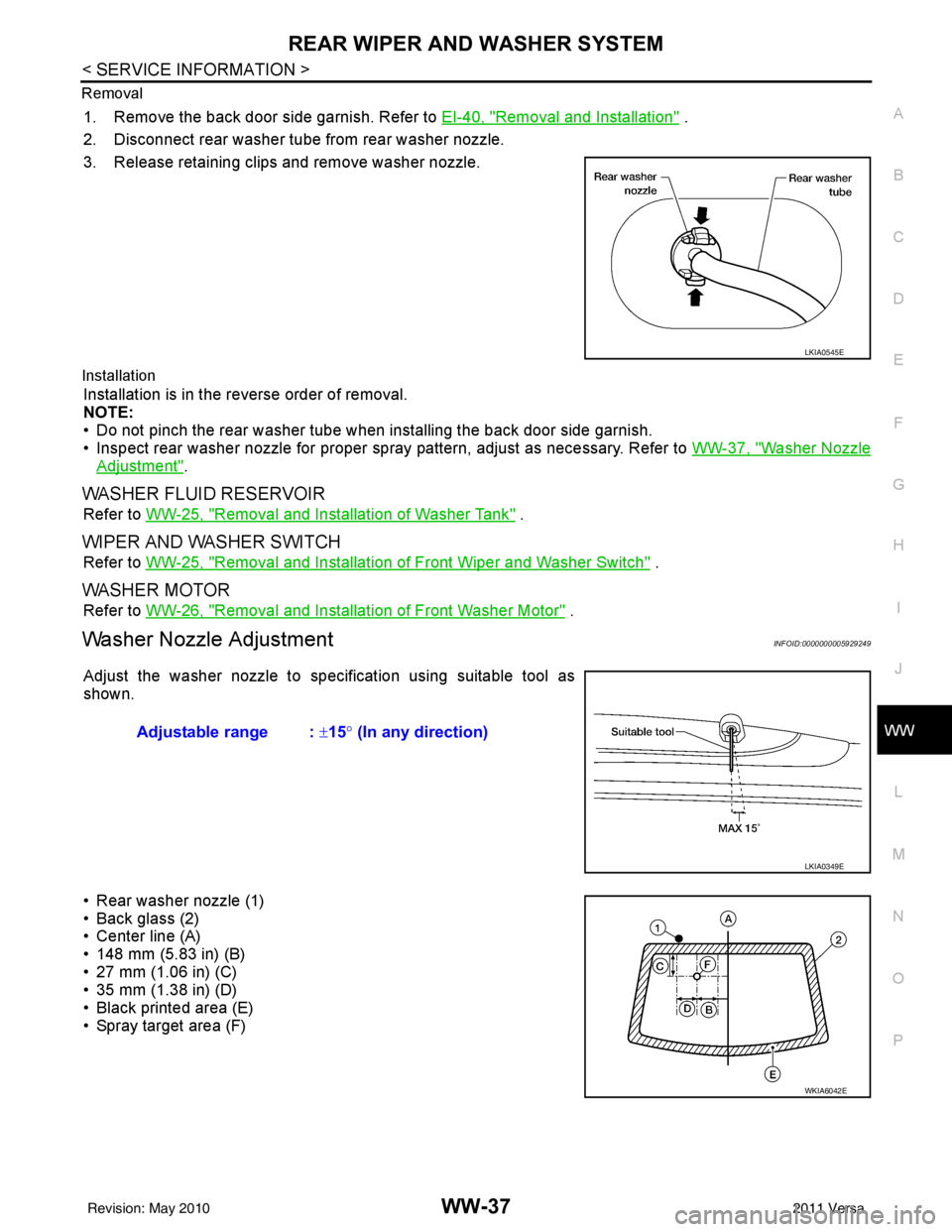
Adjust the washer nozzle to specification using suitable tool as
shown.
• Rear washer nozzle (1)
• Back glass (2)
• Center line (A)
• 148 mm (5.83 in) (B)
• 27 mm (1.06 in) (C)
• 35 mm (1.38 in) (D)
• Black printed area (E)
• Spray target area (F)
LKIA0545E
Adjustable range : ±15° (In any direction)
LKIA0349E
WKIA6042E
Revision: May 2010 2011 Versa