2011 NISSAN TIIDA Front suspension
[x] Cancel search: Front suspensionPage 1 of 3787

-1
QUICK REFERENCE INDEX
AGENERAL INFORMATIONGIGeneral Information
BENGINEEMEngine Mechanical
LUEngine Lubrication System
COEngine Cooling System
ECEngine Control System
FLFuel System
EXExhaust System
ACCAccelerator Control System
CTRANSMISSION/
TRANSAXLECLClutch System
MTManual Transaxle
ATAutomatic Transaxle
CVTCVT
DDRIVELINE/AXLEFAXFront Axle
RAXRear Axle
ESUSPENSIONFSUFront Suspension
RSURear Suspension
WTRoad Wheels & Tires
FBRAKESBRBrake System
PBParking Brake System
BRCBrake Control System
GSTEERINGPSPower Steering System
STCSteering Control System
HRESTRAINTSSBSeat Belts
SRSSupplemental Restraint System (SRS)
IBODYBLBody, Lock & Security System
GWGlasses, Window System & Mirrors
RFRoof
EIExterior & Interior
IPInstrument Panel
SESeat
JAIR CONDITIONERMTCManual Air Conditioner
KELECTRICALSCStarting & Charging System
LTLighting System
DIDriver Information System
WWWiper, Washer & Horn
BCSBody Control System
LANLAN System
AVAudio Visual, Navigation & Telephone System
ACSAuto Cruise Control System
PGPower Supply, Ground & Circuit Elements
LMAINTENANCEMAMaintenance
Edition: May 2010
Revision: May 2010
Publication No. SM1E-1C11U0
B
D
© 2010 NISSAN NORTH AMERICA, INC.
All rights reserved. No part of this Service Manual may be reproduced or stored in a retrieval system, or transmitted in any
form, or by any means, electronic, mechanical, photo-copying, recording or otherwise, without the prior written permission
of Nissan North America Inc.
A
C
E
F
G
H
I
J
K
L
M
Page 778 of 3787

BL-268
< SERVICE INFORMATION >
BODY REPAIR
4. Front pillar inner reinforcement (RH&LH)
5. Lower dash reinforcement
6. 4th crossmember (RH&LH)
7. Front side member rear extension (RH&LH)
8. 3rd crossmember (RH&LH)
9. Front seat outer rear bracket (RH&LH)
10. Front seat inner rear bracket (RH&LH)
11. 2nd crossmember (RH&LH)
12. Front seat outer front bracket (RH&LH)
13. Front seat inner front bracket (RH&LH)
14. Fender bracket (RH&LH)
15. Strut housing assembly RH
16. Cowl top side upper (RH&LH)
17. Front strut housing (RH&LH)
18. Upper torque rod reinforcement
19. Closing plate assembly RH
20. Engine mount reinforcement
21. Strut tower front reinforcement RH
22. Front hoodledge lower RH
23. Frame bracket outer (RH&LH)
24. Front bumper support bracket (RH&LH)
25. Closing plate (RH&LH)
26. Front suspension rear bracket (RH&LH)
27. Front side member outrigger (RH&LH)
28. Front side member assembly (RH&LH)
29. Front side member (RH&LH)
30. Frame bracket (RH&LH)
31. Closing plate assembly LH
32. Hoodledge connector (RH&LH)
33. Radiator core side support (RH&LH)
34. Radiator core support upper (RH&LH)
35. Hoodledge upper (RH&LH)
36. Hoodledge reinforcement assembly (RH&LH)
37. Dash side (RH&LH)
38. Dash side assembly (RH& LH)
39. Front floor reinforcement (RH&LH)
40. Front floor front (RH&LH)
41. Front floor center
42. Rear seat crossmember
43. Rear center crossmember
44. Rear seat upper crossmember
45. Rear side member (RH&LH)
46. Sill inner extension (RH&LH)
47. Rear side member extension (RH&LH)
48. Rear side member assembly (RH & LH)
49. Rear floor front
50. Rear floor front assembly
51. Rear floor side (RH&LH)
52. Rear floor rear
Revision: May 20102011 Versa
Page 831 of 3787
BODY REPAIRBL-321
< SERVICE INFORMATION >
C
DE
F
G H
J
K L
M A
B
BL
N
O P
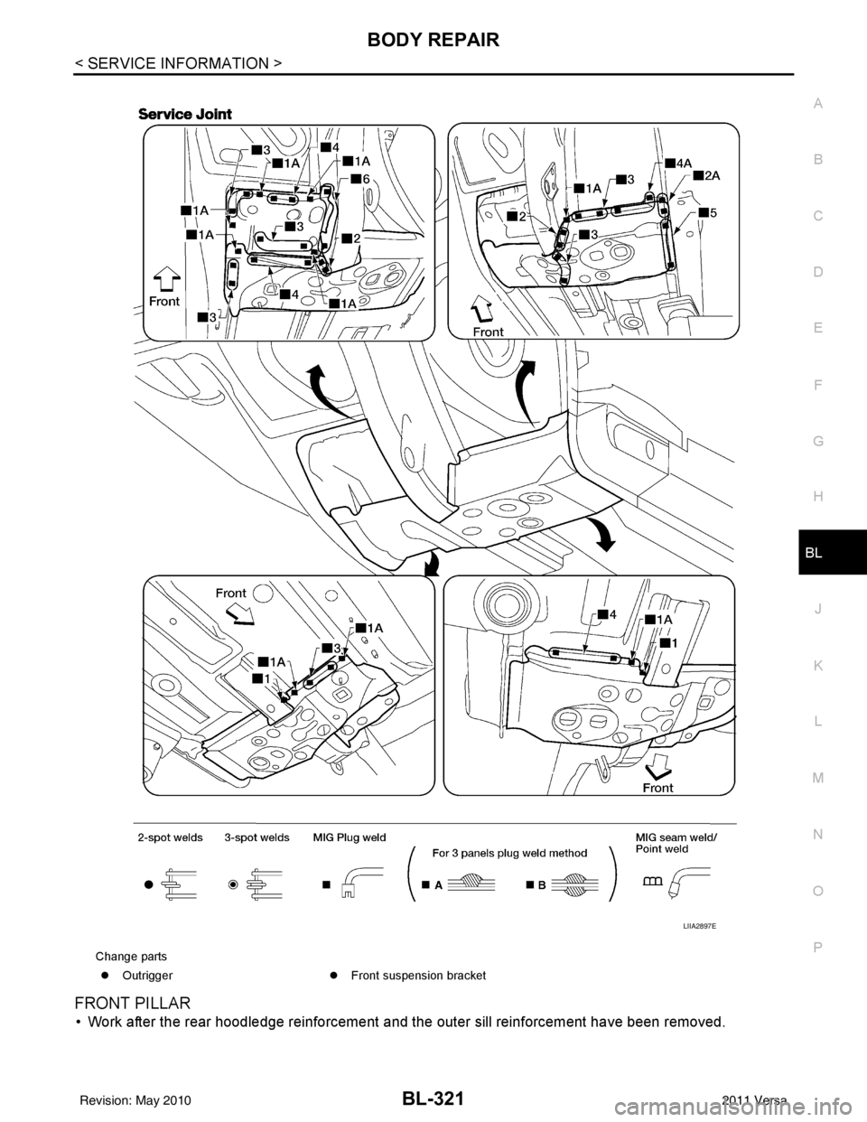
FRONT PILLAR
• Work after the rear hoodledge reinforcement and the outer sill reinforcement have been removed.
Change parts z Outrigger zFront suspension bracket
LIIA2897E
Revision: May 2010 2011 Versa
Page 923 of 3787
![NISSAN TIIDA 2011 Service Repair Manual BRC-34
< SERVICE INFORMATION >[ABS]
WHEEL SENSORS
• When installing front wheel senso
r, press rubber grommets of strut bracket and body all the way in
until they get locked, and be careful not to](/manual-img/5/57396/w960_57396-922.png "NISSAN TIIDA 2011 Service Repair Manual BRC-34
< SERVICE INFORMATION >[ABS]
WHEEL SENSORS
• When installing front wheel senso
r, press rubber grommets of strut bracket and body all the way in
until they get locked, and be careful not to")
BRC-34
< SERVICE INFORMATION >[ABS]
WHEEL SENSORS
• When installing front wheel senso
r, press rubber grommets of strut bracket and body all the way in
until they get locked, and be careful not to apply a twist to harness. Harness should not be twisted
after installation. (Install it with harness paint mark on body side grommet facing front of vehicle,
and the strut side grommet facing outside of vehicle.)
REAR WHEEL SENSOR
Removal
CAUTION:
• As much as possible, avoid rotating wheel sensor when removing it . Pull wheel sensors out without
pulling on sensor harness.
• Take care to avoid damaging wheel sensor edges or rotor teeth. Remove wheel sensor first before
removing front or rear wheel hub. This is to avoid damage to wheel sensor wiring and loss of sensor
function.
1. Disconnect the rear wheel sensor connector.
2. Remove the rear wheel sensor.
Installation
Installation is in the reverse order of removal.
CAUTION:
• When installing, make sure there is no foreign material such as iron chips on and in the mounting
hole of the wheel sensor. Make sure no foreign material has been caught in the sensor rotor. Remove
any foreign material and clean the mount.
• When installing rear wheel sensor, press rubber grommets of suspension arm bracket and harness
of side member all the way in until they get locked , and be careful not to apply a twist to harness.
Harness should not be twisted af ter installation. (Aim the paint mark upward of vehicle.)
Revision: May 2010 2011 Versa
Page 974 of 3787
![NISSAN TIIDA 2011 Service Repair Manual ON-VEHICLE SERVICEBRC-85
< SERVICE INFORMATION > [VDC/TCS/ABS]
C
D
E
G H
I
J
K L
M A
B
BRC
N
O P
ON-VEHICLE SERVICE
Adjustment of Steering Angle Sensor Neutral PositionINFOID:0000000005928506
After re](/manual-img/5/57396/w960_57396-973.png "NISSAN TIIDA 2011 Service Repair Manual ON-VEHICLE SERVICEBRC-85
< SERVICE INFORMATION > [VDC/TCS/ABS]
C
D
E
G H
I
J
K L
M A
B
BRC
N
O P
ON-VEHICLE SERVICE
Adjustment of Steering Angle Sensor Neutral PositionINFOID:0000000005928506
After re")
ON-VEHICLE SERVICEBRC-85
< SERVICE INFORMATION > [VDC/TCS/ABS]
C
D
E
G H
I
J
K L
M A
B
BRC
N
O P
ON-VEHICLE SERVICE
Adjustment of Steering Angle Sensor Neutral PositionINFOID:0000000005928506
After removing/installing or replacing ABS actuator and electric unit (control unit), steering angle sensor, steer-
ing and suspension components which affect wheel alignment or after adjusting wheel alignment, be sure to
adjust neutral position of steering angle sensor before running vehicle.
NOTE:
Adjustment of steering angle sensor neutral position requires CONSULT-III.
1. Stop vehicle with front wheels in straight-ahead position.
2. Connect CONSULT-III to data link connector on vehicle, and turn ignition switch ON (do not start engine).
3. Touch “ABS”, “WORK SUPPORT” and “ST ANGLE SENSOR ADJUSTMENT” on CONSULT-III screen in
this order.
4. Touch “START”. CAUTION:
Do not touch steering wheel whil e adjusting steering angle sensor.
5. After approximately 10 seconds, touch “END”. (After approximately 60 seconds, it ends automatically.)
6. Turn ignition switch OFF, then turn it ON again.
7. Run vehicle with front wheels in straight-ahead position, then stop.
8. Select “DATA MONITOR”, “SELECTION FROM MENU”, and “STR ANGLE SIG” on CONSULT-III screen.
Then check that “STR ANGLE SIG” is within 0 ±2.5 deg. If value is more than specification, repeat steps 1
to 5.
9. Erase memory of ABS actuator and electric unit (control unit) and ECM.
10. Turn ignition switch to OFF.
Revision: May 2010 2011 Versa
Page 976 of 3787
![NISSAN TIIDA 2011 Service Repair Manual WHEEL SENSORSBRC-87
< SERVICE INFORMATION > [VDC/TCS/ABS]
C
D
E
G H
I
J
K L
M A
B
BRC
N
O P
• When installing front wheel sensor, press rubber gr ommets of strut bracket and body all the way in
unti](/manual-img/5/57396/w960_57396-975.png "NISSAN TIIDA 2011 Service Repair Manual WHEEL SENSORSBRC-87
< SERVICE INFORMATION > [VDC/TCS/ABS]
C
D
E
G H
I
J
K L
M A
B
BRC
N
O P
• When installing front wheel sensor, press rubber gr ommets of strut bracket and body all the way in
unti")
WHEEL SENSORSBRC-87
< SERVICE INFORMATION > [VDC/TCS/ABS]
C
D
E
G H
I
J
K L
M A
B
BRC
N
O P
• When installing front wheel sensor, press rubber gr ommets of strut bracket and body all the way in
until they get locked, and be careful not to apply a twist to harness. Harness should not be twisted
after installation. (Install it with harness paint mark on body side grommet facing front of vehicle,
and the strut side grommet facing outside of vehicle.)
REAR WHEEL SENSOR
Removal
CAUTION:
• As much as possible, avoid rotating wheel sensor when removing it . Pull wheel sensors out without
pulling on sensor harness.
• Take care to avoid damaging wheel sensor edges or rotor teeth. Remove wheel sensor first before removing front or rear wheel hub. This is to avo id damage to wheel sensor wiring and loss of sensor
function.
1. Disconnect the rear wheel sensor connector.
2. Remove the rear wheel sensor.
Installation
Installation is in the reverse order of removal.
CAUTION:
• When installing, make sure there is no foreign mate rial such as iron chips on and in the mounting
hole of the wheel sensor. Make sure no foreign material has been caught in the sensor rotor. Remove
any foreign material and clean the mount.
• When installing rear wheel sensor, press rubber grommets of suspension arm bracket and harness
of side member all the way in until they get locked , and be careful not to apply a twist to harness.
Harness should not be twisted after installati on. (Aim the paint mark upward of vehicle.)
Revision: May 2010 2011 Versa
Page 2647 of 3787
NOISE, VIBRATION AND HARSHNESS (NVH) TROUBLESHOOTINGFAX-5
< SERVICE INFORMATION >
CEF
G H
I
J
K L
M A
B
FA X
N
O P
NOISE, VIBRATION AND HARSHN ESS (NVH) TROUBLESHOOTING
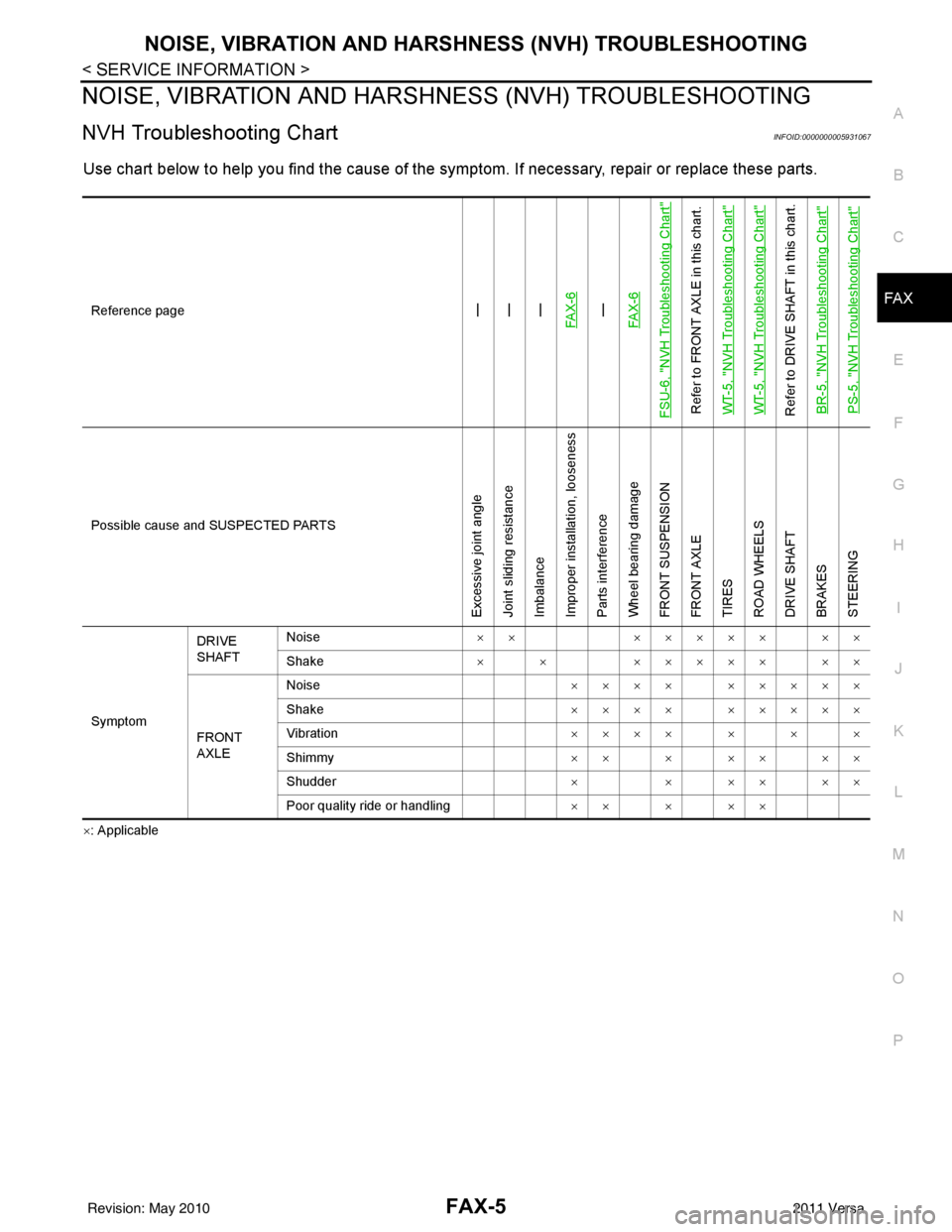
NVH Troubleshooting ChartINFOID:0000000005931067
Use chart below to help you find the cause of the symptom. If necessary, repair or replace these parts.
×: ApplicableReference page
—
—
—
FAX-6—
FAX-6
FSU-6, "
NVH Troubleshooting Chart
"
Refer to FRONT AXLE in this chart.
WT-5, "
NVH Troubleshooting Chart
"
WT-5, "
NVH Troubleshooting Chart
"
Refer to DRIVE SHAFT in this chart. BR-5, "
NVH Troubleshooting Chart
"
PS-5, "
NVH Troubleshooting Chart
"
Possible cause and SUSPECTED PARTS
Excessive joint angle
Joint sliding resistance
Imbalance
Improper installation, looseness
Parts interference
Wheel bearing damage
FRONT SUSPENSION
FRONT AXLE
TIRES
ROAD WHEELS
DRIVE SHAFT
BRAKES
STEERING
SymptomDRIVE
SHAFT
Noise
××××××× ××
Shake × × ××××× ××
FRONT
AXLE Noise
×××× ×××××
Shake ×××× ×××××
Vibration ×××××××
Shimmy ×××××××
Shudder × × ×× ××
Poor quality ride or handling ×××××
Revision: May 2010 2011 Versa
Page 2648 of 3787
FAX-6
< SERVICE INFORMATION >
FRONT WHEEL HUB AND KNUCKLE
FRONT WHEEL HUB AND KNUCKLE
On-Vehicle Inspection and ServiceINFOID:0000000005931068
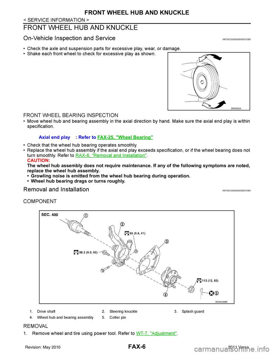
• Check the axle and suspension parts for excessive play, wear, or damage.
• Shake each front wheel to check for excessive play as shown.
FRONT WHEEL BEARING INSPECTION
• Move wheel hub and bearing assembly in the axial direction by hand. Make sure the axial end play is within
specification.
• Check that the wheel hub bearing operates smoothly.
• Replace the wheel hub assembly if the axial end play exceeds specification, or if the wheel bearing does not turn smoothly. Refer to RAX-6, "
Removal and Installation".
CAUTION:
The wheel hub assembly does not requ ire maintenance. If any of the following symptoms are noted,
replace the wheel hub assembly.
• Growling noise is emitted from the wheel hub bearing during operation.
• Wheel hub bearing drags or turns roughly.
Removal and InstallationINFOID:0000000005931069
COMPONENT
REMOVAL
1. Remove wheel and tire using power tool. Refer to WT-7, "Adjustment".
SMA525A
Axial end play : Refer to FAX-25, "Wheel Bearing"
1. Drive shaft 2. Steering knuckle3. Splash guard
4. Wheel hub and bearing assembly 5. Cotter pin
WDIA0366E
Revision: May 2010 2011 Versa