2011 NISSAN TIIDA cowl
[x] Cancel search: cowlPage 2334 of 3787

EI-4
< PRECAUTION >
PRECAUTIONS
5. When the repair work is completed, return the ignition switch to the ″LOCK ″ position before connecting
the battery cables. (At this time, the steering lock mechanism will engage.)
6. Perform a self-diagnosis check of a ll control units using CONSULT-III.
PrecautionINFOID:0000000005929547
• When removing or disassembling any part, be careful not to damage or deform it. Protect parts which may
get in the way with cloth.
• When removing parts with a screwdriver or other tool, protect parts by wrapping them with vinyl or tape.
• Keep removed parts protected with cloth.
• If a clip is deformed or damaged, replace it.
• If an unreusable part is removed, replace it with a new one.
• Tighten bolts and nuts firmly to the specified torque.
• After re-assembly has been completed, make sure each part functions correctly.
• Remove stains in the following way.
- Water-soluble stains:
Dip a cloth in warm water, and squeeze tightly. After wiping the stain, wipe with a soft dry cloth.
- Oil stain:
Dissolve a synthetic detergent in warm water (density of 2 to 3% or less), dip the cloth, then clean off the
stain with the cloth. Next, dip the soft cloth in fr esh water, and then squeeze it tightly. Then clean off the
detergent completely. Then wipe the area with a soft dry cloth.
• Do not use any organic solvent, such as thinner or benzine.
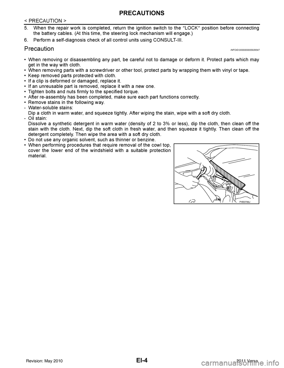
• When performing procedures that require removal of the cowl top, cover the lower end of the windshield with a suitable protection
material.
PIIB3706J
Revision: May 2010 2011 Versa
Page 2354 of 3787

EI-24
< ON-VEHICLE REPAIR >
COWL TOP
COWL TOP
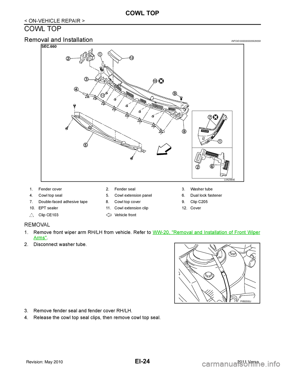
Removal and InstallationINFOID:0000000005929559
REMOVAL
1. Remove front wiper arm RH/LH from vehicle. Refer to WW-20, "Removal and Installation of Front Wiper
Arms".
2. Disconnect washer tube.
3. Remove fender seal and fender cover RH/LH.
4. Release the cowl top seal clips, then remove cowl top seal.
LIIA2565E
1. Fender cover 2. Fender seal3. Washer tube
4. Cowl top seal 5. Cowl extension panel6. Dual lock fastener
7. Double-faced adhesive tape 8. Cowl top cover 9. Clip C205
10. EPT sealer 11. Cowl extension clip12. Cover
Clip CE103 Vehicle front
PIIB2555J
Revision: May 2010 2011 Versa
Page 2355 of 3787

COWL TOPEI-25
< ON-VEHICLE REPAIR >
C
DE
F
G H
J
K L
M A
B
EI
N
O P
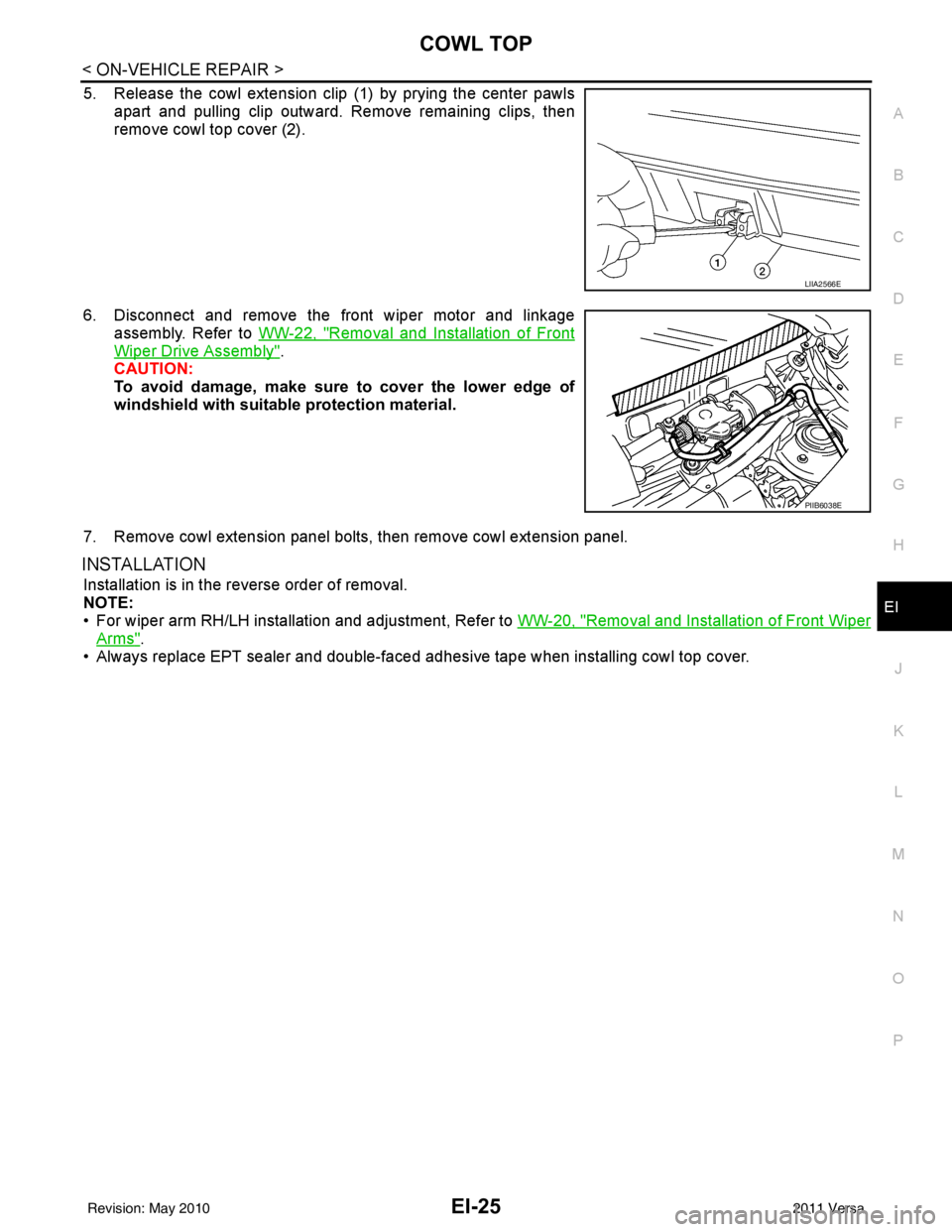
5. Release the cowl extension clip (1) by prying the center pawls apart and pulling clip outward. Remove remaining clips, then
remove cowl top cover (2).
6. Disconnect and remove the front wiper motor and linkage assembly. Refer to WW-22, "
Removal and Installation of Front
Wiper Drive Assembly".
CAUTION:
To avoid damage, make sure to cover the lower edge of
windshield with suitable protection material.
7. Remove cowl extension panel bolts, then remove cowl extension panel.
INSTALLATION
Installation is in the reverse order of removal.
NOTE:
• For wiper arm RH/LH installation and adjustment, Refer to WW-20, "
Removal and Installation of Front Wiper
Arms".
• Always replace EPT sealer and double-faced adhesive tape when installing cowl top cover.
LIIA2566E
PIIB6038E
Revision: May 2010 2011 Versa
Page 2391 of 3787

EM-1
ENGINE
C
DE
F
G H
I
J
K L
M
SECTION EM
A
EM
N
O P
CONTENTS
ENGINE MECHANICAL
HR16DE
PRECAUTION ....... ........................................
4
PRECAUTIONS .............................................. .....4
Precaution for Supplemental Restraint System
(SRS) "AIR BAG" and "SEAT BELT PRE-TEN-
SIONER" ............................................................. ......
4
Precaution for Procedure without Cowl Top Cover ......4
Precaution for Drain Coolant .....................................4
Precaution for Disconnecting Fuel Piping ........... ......4
Precaution for Removal and Disassembly ................5
Precaution for Inspection, Repair and Replace-
ment .................................................................... ......
5
Precaution for Assembly and Installation ..................5
Parts Requiring Angular Tightening ..........................5
Precaution for Liquid Gasket ............................... ......5
PREPARATION ............................................7
PREPARATION .............................................. .....7
Special Service Tools .......................................... ......7
Commercial Service Tools ........................................8
SYMPTOM DIAGNOSIS ..............................11
NOISE, VIBRATION AND HARSHNESS
(NVH) TROUBLESHOOTING ........................ ....
11
NVH Troubleshooting - Engine Noise ................. ....11
Use the Chart Below to Help You Find the Cause
of the Symptom .......................................................
12
ON-VEHICLE MAINTENANCE ....................13
DRIVE BELTS ................................................ ....13
Checking ............................................................. ....13
Tension Adjustment ................................................13
Removal and Installation .........................................14
AIR CLEANER FILTER .................................. ....16
Removal and Installation .........................................16
SPARK PLUG ...................................................17
Exploded View ..................................................... ....17
Removal and Installation .........................................17
CAMSHAFT VALVE CLEARANCE ..................19
Inspection and Adjustment ......................................19
COMPRESSION PRESSURE ...........................22
Inspection ................................................................22
ON-VEHICLE REPAIR .................................23
DRIVE BELT IDLER PULLEY ..........................23
Exploded View ..................................................... ....23
Removal and Installation .........................................23
AIR CLEANER AND AIR DUCT .......................25
Exploded View .........................................................25
Removal and Installation .........................................25
Inspection ................................................................26
INTAKE MANIFOLD .........................................27
Exploded View .........................................................27
Removal and Installation .........................................27
EXHAUST MANIFOLD ......................................30
Exploded View .........................................................30
Removal and Installation .........................................30
FUEL INJECTOR AND FUEL TUBE ................33
Exploded View .........................................................33
Removal and Installation .........................................33
Inspection ................................................................37
OIL PAN (LOWER) ...........................................39
Exploded View .........................................................39
Removal and Installation .........................................39
Inspection ................................................................41
OIL PAN (UPPER) AND OIL STRAINER .........42
Component ..............................................................42
Removal and Installation .........................................42
Inspection ................................................................45
Revision: May 2010 2011 Versa
Page 2392 of 3787

EM-2
IGNITION COIL, SPARK PLUG AND ROCK-
ER COVER .........................................................
46
Exploded View ........................................................46
Removal and Installation ........................................46
TIMING CHAIN ............................................... ...49
Exploded View ..................................................... ...49
Removal and Installation ........................................49
Inspection ...............................................................57
CAMSHAFT .......................................................59
Exploded View ..................................................... ...59
Removal and Installation ........................................59
Inspection ...............................................................65
OIL SEAL ...........................................................70
VALVE OIL SEAL .................................................. ...70
VALVE OIL SEAL : Removal and Installation .........70
FRONT OIL SEAL .................................................. ...70
FRONT OIL SEAL : Removal and Installation ........71
REAR OIL SEAL .................................................... ...71
REAR OIL SEAL : Removal and Installation ..........71
CYLINDER HEAD ........................................... ...73
Removal and Installation ..................................... ...73
Disassembly and Assembly ....................................76
REMOVAL AND INSTALLATION ...............82
ENGINE ASSEMBLY ...................................... ...82
Exploded View ..................................................... ...82
Removal and Installation ........................................82
Inspection ...............................................................85
DISASSEMBLY AND ASSEMBLY .............87
ENGINE STAND SETTING ............................. ...87
Setting ................................................................. ...87
ENGINE UNIT ....................................................88
Disassembly ........................................................ ...88
Assembly ................................................................88
CYLINDER BLOCK ...........................................89
Exploded View ..................................................... ...89
Disassembly and Assembly ....................................90
Inspection ...............................................................97
HOW TO SELECT PISTON AND BEARING ...106
Description ........................................................... ..106
Connecting Rod Bearing .......................................106
Main Bearing .........................................................108
SERVICE DATA AND SPECIFICATIONS
(SDS) ........................................................ ..
111
SERVICE DATA AND SPECIFICATIONS
(SDS) ............................................................... .
111
General Specification .......................................... ..111
Drive Belts ............................................................ .111
Spark Plug ............................................................112
Exhaust Manifold ..................................................112
Camshaft ...............................................................112
Cylinder Head .......................................................114
Cylinder Block .......................................................116
Connecting Rod Bearing .......................................119
Main Bearing .........................................................120
MR18DE
SERVICE INFORMATION .. .......................
122
PRECAUTIONS .............................................. ..122
Precaution for Supplemental Restraint System
(SRS) "AIR BAG" and "SEAT BELT PRE-TEN-
SIONER" .............................................................. .
122
Precaution Necessary for Steering Wheel Rota-
tion After Battery Disconnect ................................
122
Precaution for Procedure without Cowl Top Cover .123
Precaution for Drain Coolant .................................123
Precaution for Disconnecting Fuel Piping ............ .123
Precaution for Removal and Disassembly ............123
Precaution for Inspection, Repair and Replace-
ment ......................................................................
123
Precaution for Assembly and Installation ............. .123
Parts Requiring Angular Tightening ......................124
Precaution for Liquid Gasket .................................124
PREPARATION ................................................126
Special Service Tool ............................................ .126
Commercial Service Tool ......................................128
NOISE, VIBRATION AND HARSHNESS
(NVH) TROUBLESHOOTING ...........................
130
NVH Troubleshooting - Engine Noise .................. .130
Use the Chart Below to Help You Find the Cause
of the Symptom .................................................... .
131
DRIVE BELTS ..................................................132
Component .......................................................... .132
Checking Drive Belts .............................................132
Tension Adjustment ..............................................132
Removal and Installation .......................................132
Component .......................................................... .133
Removal and Installation of Drive Belt Auto Ten-
sioner ....................................................................
133
AIR CLEANER AND AIR DUCT .......................135
Component .......................................................... .135
Removal and Installation .......................................135
Changing Air Cleaner Filter ...................................136
INTAKE MANIFOLD ....................................... ..137
Component .......................................................... .137
Removal and Installation .......................................137
Inspection ............................................................. .139
EXHAUST MANIFOLD .....................................141
Component .......................................................... .141
Removal and Installation .......................................141
Revision: May 2010 2011 Versa
Page 2394 of 3787
![NISSAN TIIDA 2011 Service Repair Manual EM-4
< PRECAUTION >[HR16DE]
PRECAUTIONS
PRECAUTION
PRECAUTIONS
Precaution for Supplemental Restraint Syst
em (SRS) "AIR BAG" and "SEAT BELT
PRE-TENSIONER"
INFOID:0000000005930910
The Supplemental Res NISSAN TIIDA 2011 Service Repair Manual EM-4
< PRECAUTION >[HR16DE]
PRECAUTIONS
PRECAUTION
PRECAUTIONS
Precaution for Supplemental Restraint Syst
em (SRS) "AIR BAG" and "SEAT BELT
PRE-TENSIONER"
INFOID:0000000005930910
The Supplemental Res](/manual-img/5/57396/w960_57396-2393.png)
EM-4
< PRECAUTION >[HR16DE]
PRECAUTIONS
PRECAUTION
PRECAUTIONS
Precaution for Supplemental Restraint Syst
em (SRS) "AIR BAG" and "SEAT BELT
PRE-TENSIONER"
INFOID:0000000005930910
The Supplemental Restraint System such as “A IR BAG” and “SEAT BELT PRE-TENSIONER”, used along
with a front seat belt, helps to reduce the risk or severity of injury to the driver and front passenger for certain
types of collision. This system includes seat belt switch inputs and dual stage front air bag modules. The SRS
system uses the seat belt switches to determine the front air bag deployment, and may only deploy one front
air bag, depending on the severity of a collision and w hether the front occupants are belted or unbelted.
Information necessary to service the system safely is included in the SRS and SB section of this Service Man-
ual.
WARNING:
• To avoid rendering the SRS inopera tive, which could increase the risk of personal injury or death in
the event of a collision which would result in air bag inflation, all maintenance must be performed by
an authorized NISSAN/INFINITI dealer.
• Improper maintenance, including incorrect removal and installation of the SRS can lead to personal
injury caused by unintent ional activation of the system. For re moval of Spiral Cable and Air Bag
Module, see the SRS section.
• Do not use electrical test equipmen t on any circuit related to the SRS unless instructed to in this
Service Manual. SRS wiring harn esses can be identified by yellow and/or orange harnesses or har-
ness connectors.
PRECAUTIONS WHEN USING POWER TOOLS (AIR OR ELECTRIC) AND HAMMERS
WARNING:
• When working near the Airbag Diagnosis Sensor Unit or other Airbag System sensors with the Igni-
tion ON or engine running, DO NOT use air or electri c power tools or strike near the sensor(s) with a
hammer. Heavy vibration could activate the sensor( s) and deploy the air bag(s), possibly causing
serious injury.
• When using air or electric power tools or hammers , always switch the Ignition OFF, disconnect the
battery, and wait at least 3 minu tes before performing any service.
Precaution for Procedure without Cowl Top CoverINFOID:0000000005930912
When performing the procedure after removing cowl top cover, cover
the lower end of windshield.
Precaution for Drain CoolantINFOID:0000000005930913
• Drain coolant when engine is cooled.
Precaution for Disconnecting Fuel PipingINFOID:0000000005930914
• Before starting work, make sure no fire or spark producing items are in the work area.
• Release fuel pressure before disassembly.
• After disconnecting pipes, plug openings to stop fuel leakage.
PIIB3706J
Revision: May 2010 2011 Versa
Page 2420 of 3787
![NISSAN TIIDA 2011 Service Repair Manual EM-30
< ON-VEHICLE REPAIR >[HR16DE]
EXHAUST MANIFOLD
EXHAUST MANIFOLD
Exploded ViewINFOID:0000000005930939
Removal and InstallationINFOID:0000000005930940
REMOVAL
1. Remove the cowl. Refer to
EI-24, NISSAN TIIDA 2011 Service Repair Manual EM-30
< ON-VEHICLE REPAIR >[HR16DE]
EXHAUST MANIFOLD
EXHAUST MANIFOLD
Exploded ViewINFOID:0000000005930939
Removal and InstallationINFOID:0000000005930940
REMOVAL
1. Remove the cowl. Refer to
EI-24,](/manual-img/5/57396/w960_57396-2419.png)
EM-30
< ON-VEHICLE REPAIR >[HR16DE]
EXHAUST MANIFOLD
EXHAUST MANIFOLD
Exploded ViewINFOID:0000000005930939
Removal and InstallationINFOID:0000000005930940
REMOVAL
1. Remove the cowl. Refer to
EI-24, "Removal and Installation".
2. Remove heat insulator.
3. Remove exhaust front tube. Refer to EX-5, "
Component".
4. Remove the harness bracket of air fuel ratio sensor 1 from the cylinder head.
5. Remove exhaust manifold covers.
6. Remove the air fuel ratio sensor 1.
1. Exhaust manifold cover 2. Exhaust manifold cover3. Harness bracket
4. Air fuel ratio sensor 1 5. Exhaust manifold stay6. Exhaust manifold
7. Gasket 8. Stud bolt9. Heat insulator
: Engine front
PBIC4750E
Revision: May 2010 2011 Versa
Page 2473 of 3787
![NISSAN TIIDA 2011 Service Repair Manual ENGINE ASSEMBLYEM-83
< REMOVAL AND INSTALLATION > [HR16DE]
C
D
E
F
G H
I
J
K L
M A
EM
NP
O
• If items or work required are not covered by the engine section, follow the procedures in the applica-
bl NISSAN TIIDA 2011 Service Repair Manual ENGINE ASSEMBLYEM-83
< REMOVAL AND INSTALLATION > [HR16DE]
C
D
E
F
G H
I
J
K L
M A
EM
NP
O
• If items or work required are not covered by the engine section, follow the procedures in the applica-
bl](/manual-img/5/57396/w960_57396-2472.png)
ENGINE ASSEMBLYEM-83
< REMOVAL AND INSTALLATION > [HR16DE]
C
D
E
F
G H
I
J
K L
M A
EM
NP
O
• If items or work required are not covered by the engine section, follow the procedures in the applica-
ble sections.
• Always use the support poin t specified for lifting.
• Use either 2-pole lift type or separate type lift as best you can. If board-on type is used for unavoid-
able reasons, support at the rear axle jacking point with a transmission jack or similar tool before
starting work, in preparation for the backward shif t of center of gravity.
• For supporting points fo r lifting and jacking point at rear axle, refer to GI-38, "
Garage Jack and
Safety Stand and 2-Pole Lift".
REMOVAL
Outline
Remove the engine and the transaxle assembly from t he vehicle downward. Separate the engine and the tran-
saxle.
Preparation
1. Remove the hood assembly. Refer to BL-14, "Removal and Installation".
2. Remove the cowl top cover and cowl top extension assembly. Refer to EI-24, "
Removal and Installation".
3. Release fuel pressure. Refer to EC-499, "
Inspection".
4. Drain engine coolant from radiator. Refer to CO-11, "
Changing Engine Coolant".
CAUTION:
• Perform this step when the engine is cold.
• Never spill engine coolant on drive belt.
5. Remove the following parts. • Engine under cover. Refer to EI-15, "
Removal and Installation".
• Front road wheels and tires. Refer to WT-7, "
Adjustment".
• Front fender protector (RH and LH). Refer to EI-26, "
Removal and Installation".
• Battery and battery tray. Refer to SC-7, "
Removal and Installation".
• Drive belt. Refer to EM-14, "
Removal and Installation".
• Air duct and air cleaner case assembly. Refer to EM-25, "
Exploded View".
• Radiator hose (upper and lower). Refer to CO-16, "
Component".
• Disconnect cooling fan controller wiring harness.
• Remove coolant reservoir tank.
• Remove fan shroud and cooling fan assembly. Refer to CO-18, "
Component (Models with A/C)" or CO-
18, "Component (Models without A/C)".
Engine Room LH
1. Disconnect all connections of engine harness around the engine mounting insulator (LH), and then tem-
porarily secure the engine harness into the engine side.
CAUTION:
Protect connectors using a resin bag against foreign materials.
2. Remove ground cable at transaxle side.
3. Disconnect fuel feed hose at engine side. Refer to EM-33, "
Exploded View".
4. Disconnect EVAP purge hose and brake booster vacuum hose.
5. Disconnect heater hoses, and install plugs them to prevent engine coolant from draining. Refer to CO-16,
"Component".
6. Disconnect control linkage from transaxle. Refer to AT-213, "
A/T Shift Selector Removal and Installation"
(A/T), MT-14, "Exploded View" (M/T).
7. Disconnect the clutch tube at tr ansmission side (if equipped). Refer to CL-15, "
Removal and Installation".
Engine Room RH
1. Remove ground cable between front cover and vehicle.
2. Remove generator and generator br acket (A/C models). Refer to SC-25, "
Removal and Installation".
3. Remove A/C compressor with piping connected from t he engine. Temporarily secure it on the vehicle side
with a rope to avoid putting load on it (if equipped). Refer to MTC-78, "
Removal and Installation of Com-
pressor - HR16DE".
Vehicle Underbody
1. Remove front wheel sensor (LH and RH) for ABS from steering knuckle (if equipped). Refer to BRC-33,
"Removal and Installation" (ABS) or BRC-86, "Removal and Installation" (VDC/TCS/ABS).
Revision: May 2010 2011 Versa