2011 NISSAN TIIDA cowl
[x] Cancel search: cowlPage 2766 of 3787

GW-12
< SERVICE INFORMATION >
WINDSHIELD GLASS
WINDSHIELD GLASS
Removal and InstallationINFOID:0000000005929465
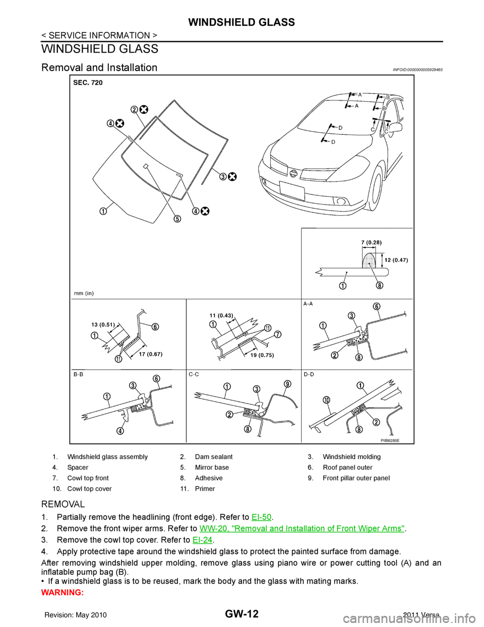
REMOVAL
1. Partially remove the headlining (front edge). Refer to EI-50.
2. Remove the front wiper arms. Refer to WW-20, "
Removal and Installation of Front Wiper Arms".
3. Remove the cowl top cover. Refer to EI-24
.
4. Apply protective tape around the windshield glas s to protect the painted surface from damage.
After removing windshield upper molding, remove glass using piano wire or power cutting tool (A) and an
inflatable pump bag (B).
• If a windshield glass is to be reused, mark the body and the glass with mating marks.
WARNING:
PIIB6285E
1. Windshield glass assembly 2. Dam sealant 3. Windshield molding
4. Spacer 5. Mirror base 6. Roof panel outer
7. Cowl top front 8. Adhesive 9. Front pillar outer panel
10. Cowl top cover 11. Primer
Revision: May 2010 2011 Versa
Page 3222 of 3787

MT-1
TRANSMISSION/TRANSAXLE
DE
F
G H
I
J
K L
M
SECTION MT
A
B
MT
N
O P
CONTENTS
MANUAL TRANSAXLE
RS5F91R
SERVICE INFORMATION .. ..........................
3
PRECAUTIONS .............................................. .....3
Precaution for Supplemental Restraint System
(SRS) "AIR BAG" and "SEAT BELT PRE-TEN-
SIONER" ............................................................. ......
3
Precaution Necessary for Steering Wheel Rota-
tion After Battery Disconnect ............................... ......
3
Precaution for Procedure without Cowl Top Cover ......4
Service Notice or Precaution .....................................4
PREPARATION ...................................................5
Special Service Tools ........................................ ......5
Commercial Service Tools .......................................7
NOISE, VIBRATION AND HARSHNESS
(NVH) TROUBLESHOOTING .............................
8
NVH Troubleshooting Chart ................................ ......8
DESCRIPTION ....................................................9
System Diagram .................................................. ......9
System Description ...................................................9
M/T OIL ...............................................................11
Draining ...................................................................11
Refilling ...................................................................11
Inspection ................................................................11
SIDE OIL SEAL ..................................................12
Removal and Installation .........................................12
POSITION SWITCH ........................................ ....13
Checking ............................................................. ....13
CONTROL LINKAGE .........................................14
Exploded View .................................................... ....14
Removal and Installation .........................................14
Inspection ............................................................ ....15
AIR BREATHER HOSE ......................................16
Exploded View .................................................... ....16
Removal and Installation ..................................... ....16
TRANSAXLE ASSEMBLY ................................17
Exploded View .........................................................17
Removal and Installation .........................................17
Disassembly and Assembly .....................................18
INPUT SHAFT AND GEAR ...............................36
Disassembly and Assembly .....................................36
MAINSHAFT AND GEAR .................................37
Disassembly and Assembly .....................................37
FINAL DRIVE ....................................................41
Disassembly and Assembly .....................................41
SHIFT CONTROL ..............................................42
Inspection ................................................................42
SERVICE DATA AND SPECIFICATIONS
(SDS) .................................................................
43
General Specification ..............................................43
RS6F94R
SERVICE INFORMATION .. .........................
44
PRECAUTIONS .................................................44
Precaution for Supplemental Restraint System
(SRS) "AIR BAG" and "SEAT BELT PRE-TEN-
SIONER" ............................................................. ....
44
Precaution Necessary for Steering Wheel Rota-
tion After Battery Disconnect ...................................
44
Precaution for Procedure without Cowl Top Cover ....45
Precaution ...............................................................45
PREPARATION .................................................46
Special Service Tool ................................................46
Commercial Service Tool ........................................48
NOISE, VIBRATION AND HARSHNESS
(NVH) TROUBLESHOOTING ...........................
51
NVH Troubleshooting Chart ....................................51
Revision: May 2010 2011 Versa
Page 3225 of 3787
![NISSAN TIIDA 2011 Service Repair Manual MT-4
< SERVICE INFORMATION >[RS5F91R]
PRECAUTIONS
5. When the repair work is completed, return the ignition switch to the
″LOCK ″ position before connecting
the battery cables. (At this time, the NISSAN TIIDA 2011 Service Repair Manual MT-4
< SERVICE INFORMATION >[RS5F91R]
PRECAUTIONS
5. When the repair work is completed, return the ignition switch to the
″LOCK ″ position before connecting
the battery cables. (At this time, the](/manual-img/5/57396/w960_57396-3224.png)
MT-4
< SERVICE INFORMATION >[RS5F91R]
PRECAUTIONS
5. When the repair work is completed, return the ignition switch to the
″LOCK ″ position before connecting
the battery cables. (At this time, the steering lock mechanism will engage.)
6. Perform a self-diagnosis check of a ll control units using CONSULT-III.
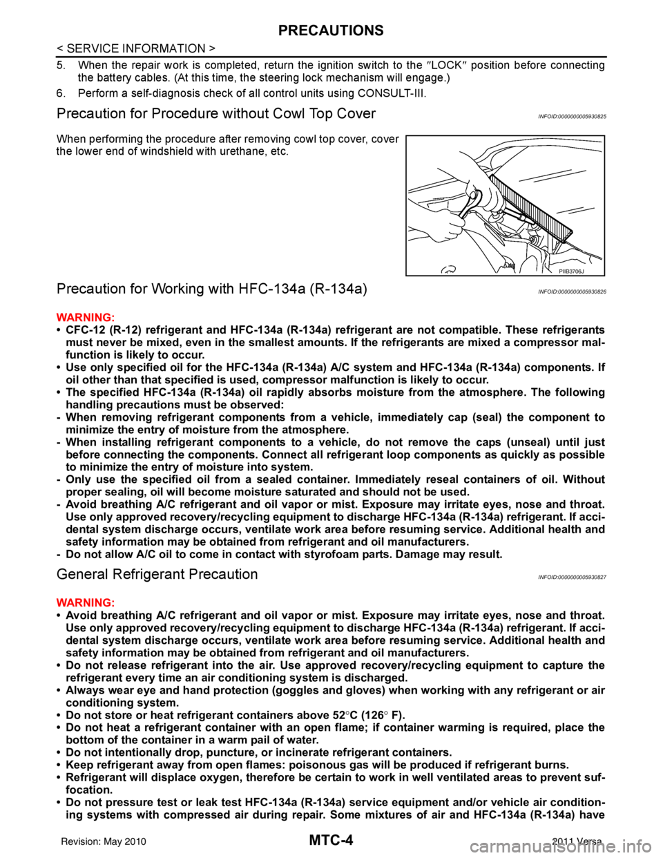
Precaution for Procedure without Cowl Top CoverINFOID:0000000005929655
When performing the procedure after removing cowl top cover, cover
the lower end of windshield with urethane, etc.
Service Notice or PrecautionINFOID:0000000005929656
•Use recommended brake fluid when adding flui d to the clutch reservoir tank. Refer to MA-14.
• Never reuse fluid drained from clutch system.
• Be careful not to splash brake fluid on painted areas.
• Use new brake fluid to clean or wash all part s of master cylinder and operating cylinder.
• Never use mineral oils such as gasoline or kerosene. It will ruin the rubber parts of the hydraulic sys-
tem.
• If transaxle assembly is removed from the vehicle , always replace CSC (Concentric slave cylinder).
Return CSC to original position to remove transaxle assembly. Dust on clutch disc sliding parts may
damage CSC seal and may cause clutch fluid leakage.
• Do not disassemble clutch master cylinder and CSC.
WARNING:
After cleaning clutch disc, clean it with a dust collector. Do not use compressed air.
PIIB3706J
Revision: May 2010 2011 Versa
Page 3266 of 3787
![NISSAN TIIDA 2011 Service Repair Manual PRECAUTIONSMT-45
< SERVICE INFORMATION > [RS6F94R]
D
E
F
G H
I
J
K L
M A
B
MT
N
O P
5. When the repair work is completed, return the ignition switch to the ″LOCK ″ position before connecting
the NISSAN TIIDA 2011 Service Repair Manual PRECAUTIONSMT-45
< SERVICE INFORMATION > [RS6F94R]
D
E
F
G H
I
J
K L
M A
B
MT
N
O P
5. When the repair work is completed, return the ignition switch to the ″LOCK ″ position before connecting
the](/manual-img/5/57396/w960_57396-3265.png)
PRECAUTIONSMT-45
< SERVICE INFORMATION > [RS6F94R]
D
E
F
G H
I
J
K L
M A
B
MT
N
O P
5. When the repair work is completed, return the ignition switch to the ″LOCK ″ position before connecting
the battery cables. (At this time, the steering lock mechanism will engage.)
6. Perform a self-diagnosis check of al l control units using CONSULT-III.
Precaution for Procedure without Cowl Top CoverINFOID:0000000005929682
When performing the procedure after removing cowl top cover, cover
the lower end of windshield with urethane, etc.
PrecautionINFOID:0000000005929683
• If transaxle assembly is removed from the vehicle, always replace CSC (Concentric Slave Cylinder).
Installed CSC returns to the original position when removing transaxle assembly. Dust on clutch disc sliding
parts may damage CSC seal, and may cause clutch fluid leakage.
• Do not reuse transaxle oil.
• Drain, fill and check transaxle oil with the vehicle on level surface.
• During removal or installation, keep inside of transaxle clear of dust or dirt.
• Check for the correct installation orientation prior to removal or disassembly. If matching marks are required, be certain they do not interfere with the function of the parts they are applied to.
• In principle, tighten bolts or nuts gradually in several steps working diagonally from inside to outside. If tight- ening sequence is specified, follow it.
• Be careful not to damage the sliding surfaces and mating surfaces of parts.
PIIB3706J
Revision: May 2010 2011 Versa
Page 3317 of 3787

MTC-1
AIR CONDITIONER
C
DE
F
G H
I
K L
M
SECTION MTC
A
B
MTC
N
O P
CONTENTS
MANUAL AIR CONDITIONER
SERVICE INFORMATION .. ..........................3
PRECAUTIONS .............................................. .....3
Precaution for Supplemental Restraint System
(SRS) "AIR BAG" and "SEAT BELT PRE-TEN-
SIONER" ............................................................. ......
3
Precaution Necessary for Steering Wheel Rota-
tion After Battery Disconnect ............................... ......
3
Precaution for Procedure without Cowl Top Cover ......4
Precaution for Working with HFC-134a (R-134a) ......4
General Refrigerant Precaution ................................4
Oil Precaution ............................................................5
Precaution for Refrigerant Connection ......................5
Precaution for Service of Compressor ................ ......8
Precaution for Service Equipment ....................... ......8
Precaution for Leak Detection Dye ...........................9
PREPARATION ..................................................11
HFC-134a (R-134a) Service Tool and Equipment ....11
Commercial Service Tool ........................................14
REFRIGERATION SYSTEM ..............................15
Refrigerant Cycle ................................................ ....15
Refrigerant System Protection ................................15
Component Part Location ................................... ....16
OIL ......................................................................17
Maintenance of Oil Quantity in Compressor ....... ....17
AIR CONDITIONER CONTROL .........................19
Control Operation ................................................ ....19
Discharge Air Flow ..................................................20
System Description .................................................20
TROUBLE DIAGNOSIS .....................................22
CONSULT-III Function (BCM) ............................. ....22
How to Perform Trouble Diagnosis for Quick and
Accurate Repair ......................................................
23
Component Parts and Harness Connector Loca-
tion ...................................................................... ....
23
Schematic ...............................................................26
Wiring Diagram - Heater - .......................................27
Wiring Diagram - A/C,M - .................................... ....28
Operational Check ...................................................31
Mode Door ...............................................................32
Air Mix Door .............................................................33
Intake Door ..............................................................34
Front Blower Motor Circuit .......................................34
Magnet Clutch Circuit (If Equipped) ..................... ....38
Insufficient Cooling ..................................................46
Insufficient Heating ..................................................53
Noise .......................................................................54
CONTROLLER ..................................................56
Removal and Installation .........................................56
Disassembly and Assembly .....................................57
THERMO CONTROL AMPLIFIER ....................58
Removal and Installation .........................................58
A/C UNIT ASSEMBLY ......................................59
Removal and Installation .........................................59
Disassembly and Assembly .....................................61
BLOWER MOTOR ............................................63
Removal and Installation .........................................63
INTAKE DOOR ..................................................64
Intake Door Cable Adjustment .................................64
AIR MIX DOOR .................................................65
Air Mix Door Cable Adjustment ...............................65
MODE DOOR ....................................................66
Mode Door Cable Adjustment .................................66
BLOWER FAN RESISTOR ...............................67
Removal and Installation .........................................67
HEATER CORE .................................................68
Removal and Installation .........................................68
DUCTS AND GRILLES .....................................69
Removal and Installation .........................................69
Revision: May 2010 2011 Versa
Page 3320 of 3787

MTC-4
< SERVICE INFORMATION >
PRECAUTIONS
5. When the repair work is completed, return the ignition switch to the ″LOCK ″ position before connecting
the battery cables. (At this time, the steering lock mechanism will engage.)
6. Perform a self-diagnosis check of a ll control units using CONSULT-III.
Precaution for Procedure without Cowl Top CoverINFOID:0000000005930825
When performing the procedure after removing cowl top cover, cover
the lower end of windshield with urethane, etc.
Precaution for Working with HFC-134a (R-134a)INFOID:0000000005930826
WARNING:
• CFC-12 (R-12) refrigerant and HFC-134a (R-134a) re frigerant are not compatible. These refrigerants
must never be mixed, even in the smallest amounts. If the refrigerants are mixed a compressor mal-
function is likely to occur.
• Use only specified oil for the HFC-134a (R-134a) A/C system and HFC-134a (R-134a) components. If
oil other than that specifi ed is used, compressor malf unction is likely to occur.
• The specified HFC-134a (R-134a) oi l rapidly absorbs moisture from the atmosphere. The following
handling precautions must be observed:
- When removing refrigerant components from a vehicle, immediately cap (seal) the component to
minimize the entry of moisture from the atmosphere.
- When installing refrigerant co mponents to a vehicle, do not remove the caps (unseal) until just
before connecting the components. Connect all refrigerant loop components as quickly as possible
to minimize the entry of moisture into system.
- Only use the specified oil from a sealed container. Immediately reseal containers of oil. Without proper sealing, oil will become moisture saturat ed and should not be used.
- Avoid breathing A/C refrigerant and oil vapor or mist. Exposure may irrita te eyes, nose and throat.
Use only approved recovery/recycling equipment to discharge HFC-134a (R-134a) refrigerant. If acci-
dental system discharge occurs, ventilate work area before resuming service. Additional health and
safety information may be obtained fr om refrigerant and oil manufacturers.
- Do not allow A/C oil to come in contact with styrofoam parts. Damage may result.
General Refrigerant PrecautionINFOID:0000000005930827
WARNING:
• Avoid breathing A/C refrigerant and oil vapor or mist. Exposure may irritate eyes, nose and throat.
Use only approved recovery/recycling equipment to discharge HFC-134a (R-134a) refrigerant. If acci-
dental system discharge occurs, ventilate work area before resuming service. Additional health and
safety information may be obtained fr om refrigerant and oil manufacturers.
• Do not release refrigerant into th e air. Use approved recovery/recycling equipment to capture the
refrigerant every time an air conditioning system is discharged.
• Always wear eye and hand protection (goggles and gloves) when worki ng with any refrigerant or air
conditioning system.
• Do not store or heat refrigerant containers above 52 °C (126° F).
• Do not heat a refrigerant container with an open flame; if container warming is required, place the
bottom of the container in a warm pail of water.
• Do not intentionally drop, puncture, or incinerate refrigerant containers.
• Keep refrigerant away from open flames: poisonou s gas will be produced if refrigerant burns.
• Refrigerant will displace oxygen, therefore be certa in to work in well ventilated areas to prevent suf-
focation.
• Do not pressure test or leak test HFC-134a (R-134a) service equipment and/or vehicle air condition-
ing systems with compressed air during repair. Some mixtures of air and HFC-134a (R-134a) have
PIIB3706J
Revision: May 2010 2011 Versa
Page 3375 of 3787

A/C UNIT ASSEMBLYMTC-59
< SERVICE INFORMATION >
C
DE
F
G H
I
K L
M A
B
MTC
N
O P
A/C UNIT ASSEMBLY
Removal and InstallationINFOID:0000000005930860
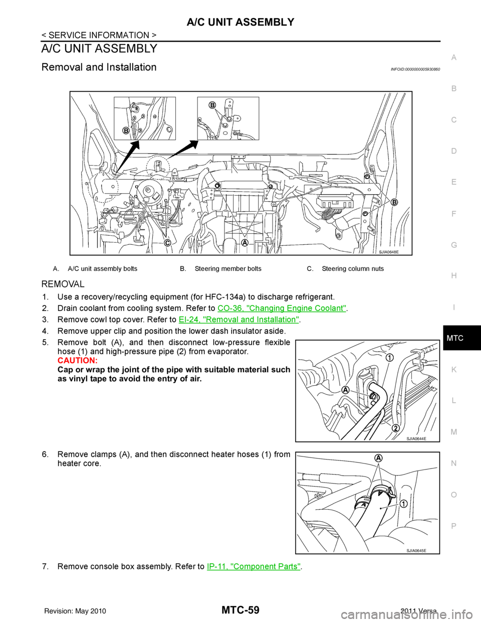
REMOVAL
1. Use a recovery/recycling equipment (f or HFC-134a) to discharge refrigerant.
2. Drain coolant from cooling system. Refer to CO-36, "
Changing Engine Coolant".
3. Remove cowl top cover. Refer to EI-24, "
Removal and Installation".
4. Remove upper clip and position the lower dash insulator aside.
5. Remove bolt (A), and then disconnect low-pressure flexible hose (1) and high-pressure pipe (2) from evaporator.
CAUTION:
Cap or wrap the joint of the pi pe with suitable material such
as vinyl tape to avoid the entry of air.
6. Remove clamps (A), and then disconnect heater hoses (1) from heater core.
7. Remove console box assembly. Refer to IP-11, "
Component Parts".
A. A/C unit assembly boltsB. Steering member boltsC. Steering column nuts
SJIA0648E
SJIA0644E
SJIA0645E
Revision: May 2010 2011 Versa
Page 3403 of 3787

REFRIGERANT LINESMTC-87
< SERVICE INFORMATION >
C
DE
F
G H
I
K L
M A
B
MTC
N
O P
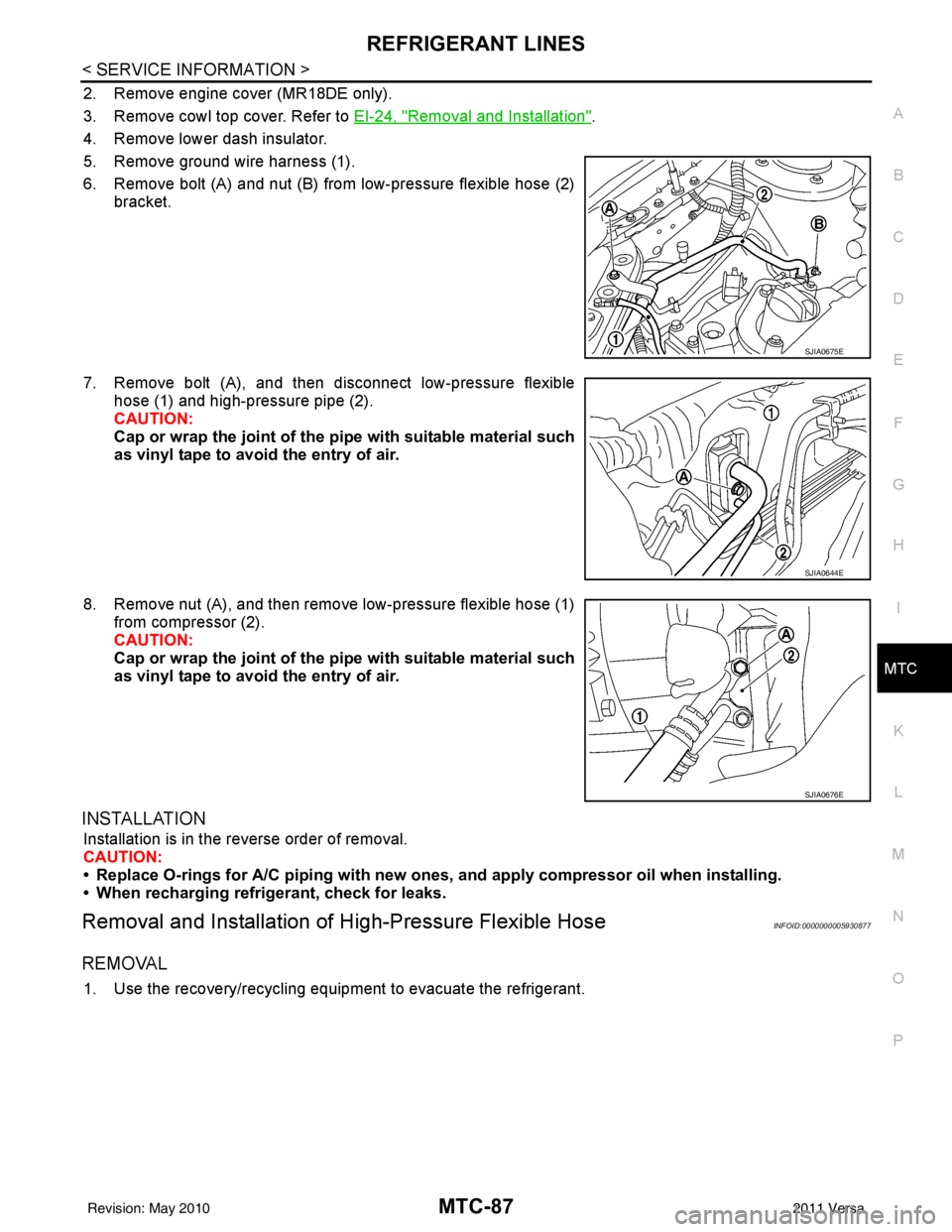
2. Remove engine cover (MR18DE only).
3. Remove cowl top cover. Refer to EI-24, "
Removal and Installation".
4. Remove lower dash insulator.
5. Remove ground wire harness (1).
6. Remove bolt (A) and nut (B) from low-pressure flexible hose (2) bracket.
7. Remove bolt (A), and then disconnect low-pressure flexible hose (1) and high-pressure pipe (2).
CAUTION:
Cap or wrap the joint of the pi pe with suitable material such
as vinyl tape to avoid the entry of air.
8. Remove nut (A), and then remove low-pressure flexible hose (1) from compressor (2).
CAUTION:
Cap or wrap the joint of the pi pe with suitable material such
as vinyl tape to avoid the entry of air.
INSTALLATION
Installation is in the reverse order of removal.
CAUTION:
• Replace O-rings for A/C piping with new on es, and apply compressor oil when installing.
• When recharging refrigerant, check for leaks.
Removal and Installation of High-Pressure Flexible HoseINFOID:0000000005930877
REMOVAL
1. Use the recovery/recycling equipment to evacuate the refrigerant.
SJIA0675E
SJIA0644E
SJIA0676E
Revision: May 2010 2011 Versa