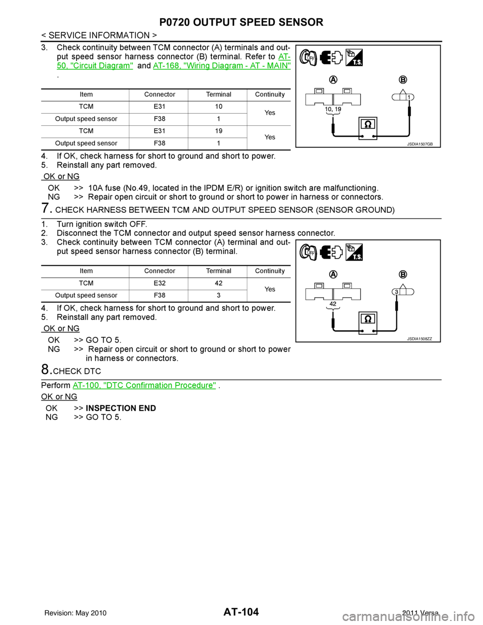
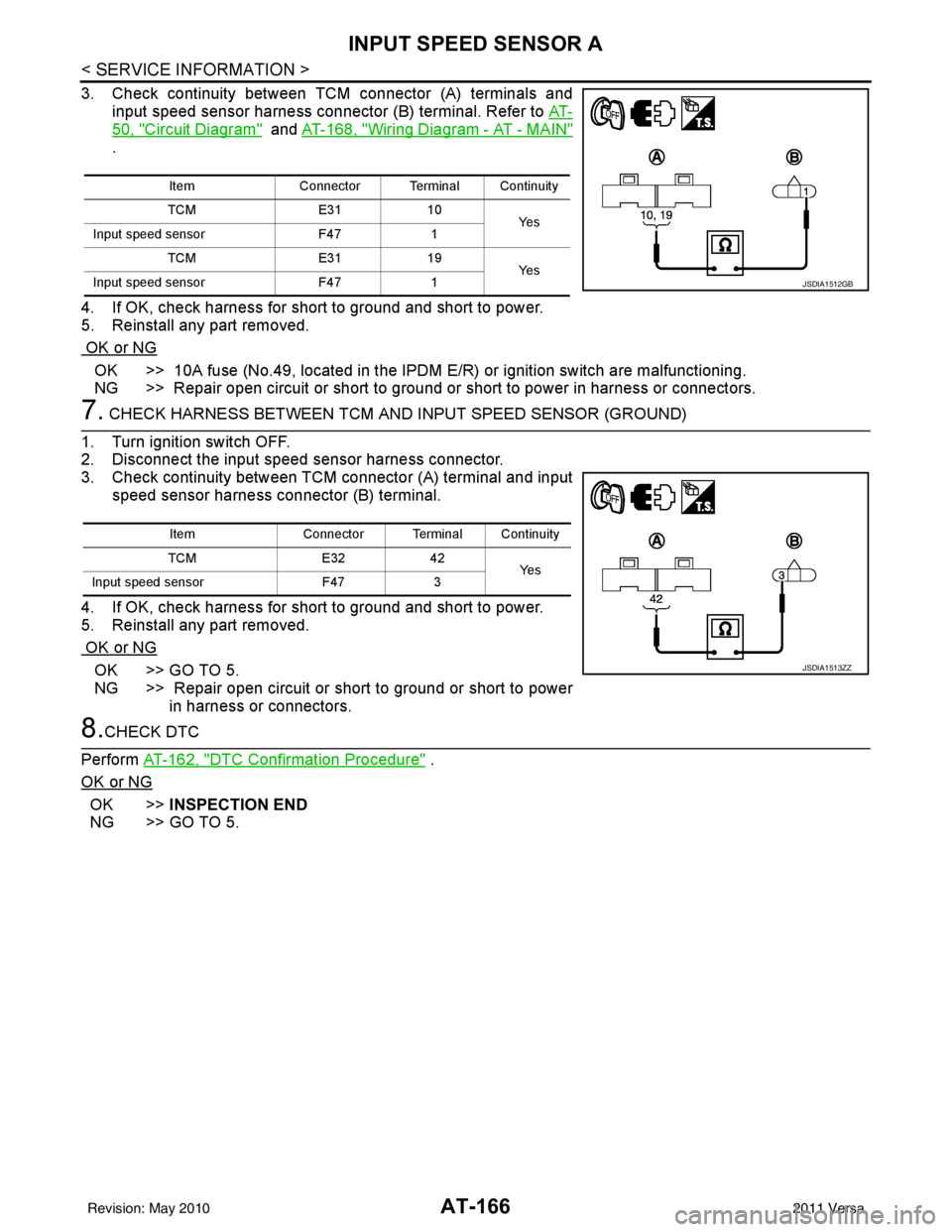
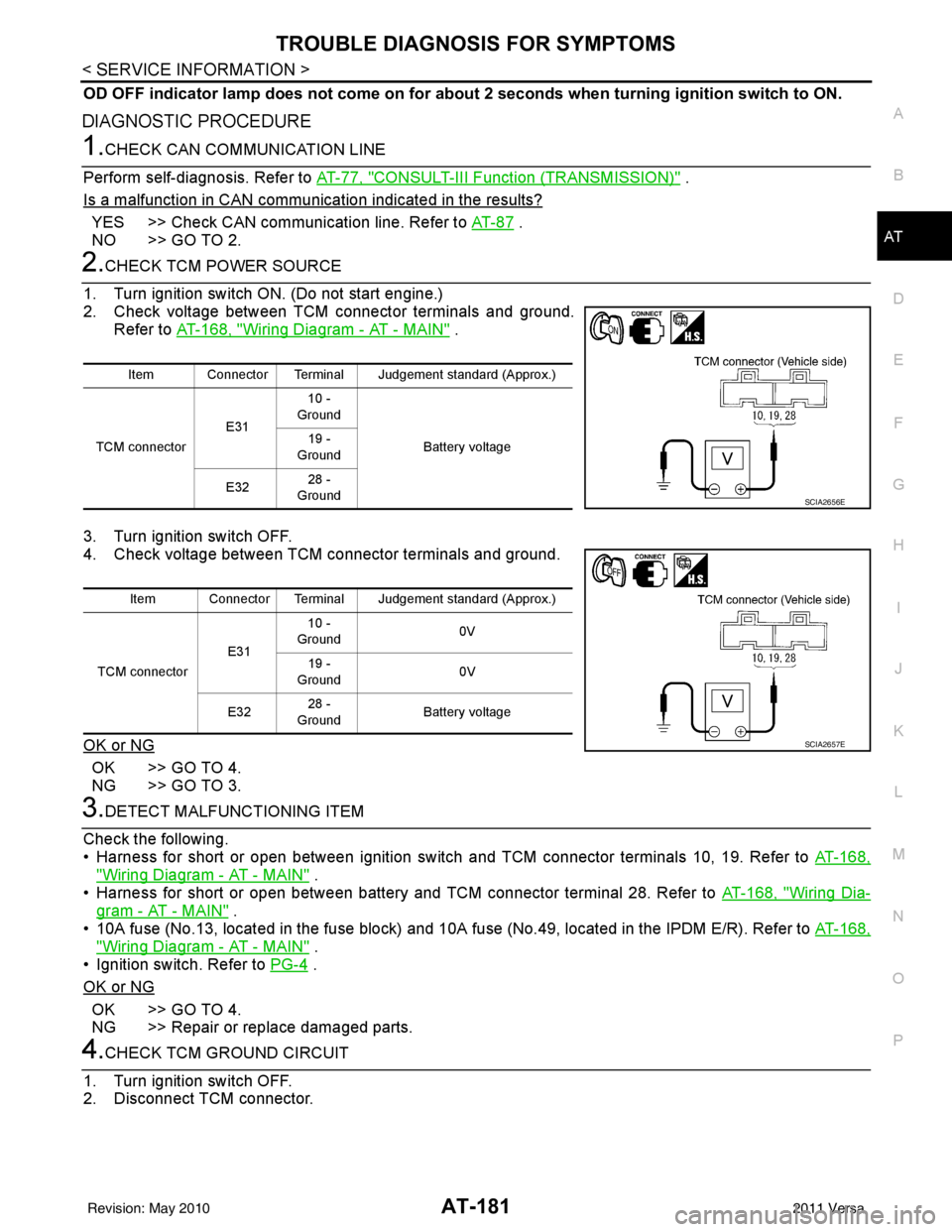
2011 NISSAN TIIDA fuse diagram
[x] Cancel search: fuse diagramPage 121 of 3787

AT-104
< SERVICE INFORMATION >
P0720 OUTPUT SPEED SENSOR
3. Check continuity between TCM connector (A) terminals and out-put speed sensor harness connector (B) terminal. Refer to AT-
50, "Circuit Diagram" and AT-168, "Wiring Diagram - AT - MAIN"
.
4. If OK, check harness for short to ground and short to power.
5. Reinstall any part removed.
OK or NG
OK >> 10A fuse (No.49, located in the IPDM E/R) or ignition switch are malfunctioning.
NG >> Repair open circuit or short to ground or short to power in harness or connectors.
7. CHECK HARNESS BETWEEN TCM AND OUTPUT SPEED SENSOR (SENSOR GROUND)
1. Turn ignition switch OFF.
2. Disconnect the TCM connector and output speed sensor harness connector.
3. Check continuity between TCM connector (A) terminal and out-
put speed sensor harness connector (B) terminal.
4. If OK, check harness for short to ground and short to power.
5. Reinstall any part removed.
OK or NG
OK >> GO TO 5.
NG >> Repair open circuit or short to ground or short to power in harness or connectors.
8.CHECK DTC
Perform AT-100, "
DTC Confirmation Procedure" .
OK or NG
OK >> INSPECTION END
NG >> GO TO 5.
Item Connector Terminal Continuity
TCM E3110
Ye s
Output speed sensor F381
TCM E3119
Ye s
Output speed sensor F381
JSDIA1507GB
Item Connector Terminal Continuity
TCM E3242
Ye s
Output speed sensor F383
JSDIA1508ZZ
Revision: May 2010 2011 Versa
Page 183 of 3787

AT-166
< SERVICE INFORMATION >
INPUT SPEED SENSOR A
3. Check continuity between TCM connector (A) terminals and
input speed sensor harness connector (B) terminal. Refer to AT-
50, "Circuit Diagram" and AT-168, "Wiring Diagram - AT - MAIN"
.
4. If OK, check harness for short to ground and short to power.
5. Reinstall any part removed.
OK or NG
OK >> 10A fuse (No.49, located in the IPDM E/R) or ignition switch are malfunctioning.
NG >> Repair open circuit or short to ground or short to power in harness or connectors.
7. CHECK HARNESS BETWEEN TCM AND INPUT SPEED SENSOR (GROUND)
1. Turn ignition switch OFF.
2. Disconnect the input speed sensor harness connector.
3. Check continuity between TCM connector (A) terminal and input speed sensor harness connector (B) terminal.
4. If OK, check harness for short to ground and short to power.
5. Reinstall any part removed.
OK or NG
OK >> GO TO 5.
NG >> Repair open circuit or short to ground or short to power in harness or connectors.
8.CHECK DTC
Perform AT-162, "
DTC Confirmation Procedure" .
OK or NG
OK >> INSPECTION END
NG >> GO TO 5.
Item Connector Terminal Continuity
TCM E3110
Ye s
Input speed sensor F471
TCM E3119
Ye s
Input speed sensor F471
JSDIA1512GB
Item Connector Terminal Continuity
TCM E3242
Ye s
Input speed sensor F473
JSDIA1513ZZ
Revision: May 2010 2011 Versa
Page 198 of 3787

TROUBLE DIAGNOSIS FOR SYMPTOMSAT-181
< SERVICE INFORMATION >
DE
F
G H
I
J
K L
M A
B
AT
N
O P
OD OFF indicator lamp does not come on for abou t 2 seconds when turning ignition switch to ON.
DIAGNOSTIC PROCEDURE
1.CHECK CAN COMMUNICATION LINE
Perform self-diagnosis. Refer to AT-77, "
CONSULT-III Function (TRANSMISSION)" .
Is a malfunction in CAN communication indicated in the results?
YES >> Check CAN communication line. Refer to AT- 8 7 .
NO >> GO TO 2.
2.CHECK TCM POWER SOURCE
1. Turn ignition switch ON. (Do not start engine.)
2. Check voltage between TCM connector terminals and ground. Refer to AT-168, "
Wiring Diagram - AT - MAIN" .
3. Turn ignition switch OFF.
4. Check voltage between TCM connector terminals and ground.
OK or NG
OK >> GO TO 4.
NG >> GO TO 3.
3.DETECT MALFUNCTIONING ITEM
Check the following.
• Harness for short or open between ignition switch and TCM connector terminals 10, 19. Refer to AT-168,
"Wiring Diagram - AT - MAIN" .
• Harness for short or open between battery and TCM connector terminal 28. Refer to AT-168, "
Wiring Dia-
gram - AT - MAIN" .
• 10A fuse (No.13, located in the fuse block) and 10A fuse (No.49, located in the IPDM E/R). Refer to AT-168,
"Wiring Diagram - AT - MAIN" .
• Ignition switch. Refer to PG-4
.
OK or NG
OK >> GO TO 4.
NG >> Repair or replace damaged parts.
4.CHECK TCM GROUND CIRCUIT
1. Turn ignition switch OFF.
2. Disconnect TCM connector.
Item Connector Terminal Judgement standard (Approx.)
TCM connector E3110 -
Ground
Battery voltage
19 -
Ground
E32 28 -
Ground
SCIA2656E
Item Connector Terminal Judgement standard (Approx.)
TCM connector E3110 -
Ground 0V
19 -
Ground 0V
E32 28 -
Ground Battery voltage
SCIA2657E
Revision: May 2010
2011 Versa
Page 480 of 3787
![NISSAN TIIDA 2011 Service Repair Manual TELEPHONEAV-83
< SERVICE INFORMATION > [AUDIO WITH NAVIGATION]
C
D
E
F
G H
I
J
L
M A
B
AV
N
O P
WorkflowINFOID:0000000006216720
Power Supply and Ground Cir cuit Inspection for Bluetooth Control UnitIN NISSAN TIIDA 2011 Service Repair Manual TELEPHONEAV-83
< SERVICE INFORMATION > [AUDIO WITH NAVIGATION]
C
D
E
F
G H
I
J
L
M A
B
AV
N
O P
WorkflowINFOID:0000000006216720
Power Supply and Ground Cir cuit Inspection for Bluetooth Control UnitIN](/manual-img/5/57396/w960_57396-479.png)
TELEPHONEAV-83
< SERVICE INFORMATION > [AUDIO WITH NAVIGATION]
C
D
E
F
G H
I
J
L
M A
B
AV
N
O P
WorkflowINFOID:0000000006216720
Power Supply and Ground Cir cuit Inspection for Bluetooth Control UnitINFOID:0000000006216721
1.CHECK FUSES
Make sure the following fuses for the Bluetooth control unit are not blown.
OK or NG
OK >> GO TO 2.
NG >> If fuse is blown, be sure to eliminate cause of malfunction before installing new fuse. Refer to PG-
6, "Wiring Diagram - POWER -".
2.CHECK POWER SUPPLY CIRCUIT
1. Disconnect Bluetooth control unit connector B121.
2. Check voltage between connector terminals and ground as fol- lows.
OK or NG
OK >> GO TO 3.
NG >> Check harness for open between Bluetooth control unit and fuse.
3.CHECK GROUND CIRCUITS
1. Turn ignition switch OFF.
Failure Message Action
“Internal failure” Replace Bluetooth control unit. Refer to AV- 8 6 , "
Removal and Installation".
“Bluetooth antenna open” 1. Inspect harness connection.
2. Replace Bluetooth antenna. Refer to AV- 8 6 , "
Removal and Installation".
“Bluetooth antenna shorted”
“Phone/Send for Hands Free System is stuck” Check steering wheel audio control switches. Refer to AV- 6 9 , "
Steering Switch
Check".
“Phone/End for the Hands Free System is stuck”
“Microphone test” (fai led interactive test) 1. Inspect harness between Bluetooth control unit and microphone.
2. Replace microphone. Refer to
AV-86, "
Removal and Installation".
Te r m i n a l s
Ignition Switch Fuse No.
Connector Terminal
B121 1
All positions27
2 ACC/ON20
3 ON/START3
Terminals Ignition switch position
(+) (–) OFF ACC ON
Connector Terminal
B121 1
Ground Battery
voltage Battery
voltage Battery
voltage
20 VBattery
voltage Battery
voltage
30 V0V Battery
voltage
WKIA4389E
Revision: May 2010 2011 Versa
Page 1135 of 3787
![NISSAN TIIDA 2011 Service Repair Manual CVT-80
< SERVICE INFORMATION >[RE0F08B]
P0720 OUTPUT SPEED SENSOR
3. Check continuity between TCM connector terminals and sec-
ondary speed sensor harness connector terminal. Refer to CVT-
37, "Circu NISSAN TIIDA 2011 Service Repair Manual CVT-80
< SERVICE INFORMATION >[RE0F08B]
P0720 OUTPUT SPEED SENSOR
3. Check continuity between TCM connector terminals and sec-
ondary speed sensor harness connector terminal. Refer to CVT-
37, "Circu](/manual-img/5/57396/w960_57396-1134.png)
CVT-80
< SERVICE INFORMATION >[RE0F08B]
P0720 OUTPUT SPEED SENSOR
3. Check continuity between TCM connector terminals and sec-
ondary speed sensor harness connector terminal. Refer to CVT-
37, "Circuit Diagram" .
4. If OK, check harness for short to ground and short to power.
5. Reinstall any part removed.
OK or NG
OK >> 10 A fuse (No. 49, located in the IPDM E/R) or ignition switch are malfunctioning.
NG >> Repair open circuit or short to ground or short to power in harness or connectors.
7. CHECK HARNESS BETWEEN TCM AND SECO NDARY SPEED SENSOR (SENSOR GROUND)
1. Turn ignition switch OFF.
2. Disconnect TCM connector and secondary speed sensor harness connector.
3. Check continuity between TCM connector terminal and second- ary speed sensor harness connector terminal.
4. If OK, check harness for short to ground and short to power.
5. Reinstall any part removed.
OK or NG
OK >> GO TO 8.
NG >> Repair open circuit or short to ground or short to power in harness or connectors.
8.CHECK DTC
Perform CVT-76, "
DTC Confirmation Procedure" .
OK or NG
OK >> INSPECTION END
NG >> GO TO 9.
9.CHECK TCM
1. Check TCM input/output signals. Refer to CVT-46, "
TCM Terminal and Reference Value" .
2. If NG, re-check TCM pin terminals for damage or loose connection with harness connector.
OK or NG
OK >> INSPECTION END
NG >> Repair or replace damaged parts.
Item Connector Terminal Continuity
TCM E3110
Ye s
Secondary speed sensor F483
TCM E3119
Ye s
Secondary speed sensor F483
SCIA2369E
Item Connector Terminal Continuity
TCM E3242
Ye s
Secondary speed sensor F481
SCIA2347E
Revision: May 2010 2011 Versa
Page 1199 of 3787
![NISSAN TIIDA 2011 Service Repair Manual CVT-144
< SERVICE INFORMATION >[RE0F08B]
TROUBLE DIAGNOSIS FOR SYMPTOMS
O/D OFF indicator lamp does not
come on for about 2 seconds when turning ignition switch ON.
DIAGNOSTIC PROCEDURE
1.CHECK CAN NISSAN TIIDA 2011 Service Repair Manual CVT-144
< SERVICE INFORMATION >[RE0F08B]
TROUBLE DIAGNOSIS FOR SYMPTOMS
O/D OFF indicator lamp does not
come on for about 2 seconds when turning ignition switch ON.
DIAGNOSTIC PROCEDURE
1.CHECK CAN](/manual-img/5/57396/w960_57396-1198.png)
CVT-144
< SERVICE INFORMATION >[RE0F08B]
TROUBLE DIAGNOSIS FOR SYMPTOMS
O/D OFF indicator lamp does not
come on for about 2 seconds when turning ignition switch ON.
DIAGNOSTIC PROCEDURE
1.CHECK CAN COMMUNICATION LINE
Perform the self-diagnosis check. Refer to CVT-48, "
CONSULT-III Function (TRANSMISSION)".
Is any malfunction of the
“U1000” indicated in the results?
YES >> Check CAN communication line. Refer to CVT-56.
NO >> GO TO 2.
2.CHECK TCM POWER SOURCE
1. Turn ignition switch ON.
2. Check voltage between TCM connector terminals and ground. Refer to CVT-114, "
Wiring Diagram - CVT - POWER".
OK or NG
OK >> GO TO 4.
NG >> GO TO 3.
3.DETECT MALFUNCTIONING ITEM
Check the following.
• Harness for short or open between ignition switch and TCM connector terminal 10, 19 Refer to CVT-114, "
Wiring Diagram - CVT - POWER".
• 10 A fuse (No.49, located in the IPDM E/R). Refer to CVT-114, "
Wiring Diagram - CVT - POWER".
• Ignition switch. Refer to PG-4
.
OK or NG
OK >> GO TO 4.
NG >> Repair or replace damaged parts.
4.CHECK TCM GROUND CIRCUIT
1. Turn ignition switch OFF.
2. Disconnect TCM connector.
3. Check continuity between TCM connector terminals and ground. Refer to CVT-114, "
Wiring Diagram - CVT - POWER".
OK or NG
OK >> GO TO 5.
NG >> Repair open circuit or short to ground or short to power in harness or connectors.
5.DETECT MALFUNCTIONING ITEM
Check the following.
• Harness and fuse for short or open between ignition switch and O/D OFF indicator lamp Refer to PG-4
.
OK or NG
OK >> GO TO 6.
NG >> Repair or replace damaged parts.
6.CHECK SYMPTOM
Name Connec-
tor Terminal
Voltage (Approx.)
Power supply E31 10
Battery voltage
19 Battery voltage
SCIA4737E
NameConnec-
tor Terminal
Continuity
Ground E32 25
Ye s
48
SCIA2671E
Revision: May 2010 2011 Versa
Page 1931 of 3787
![NISSAN TIIDA 2011 Service Repair Manual POWER SUPPLY AND GROUND CIRCUITEC-637
< SERVICE INFORMATION > [MR18DE]
C
D
E
F
G H
I
J
K L
M A
EC
NP
O
13.CHECK 20 A FUSE
1. Disconnect 20 A fuse from IPDM E/R.
2. Check 20 A fuse.
OK or NG
OK >> GO T NISSAN TIIDA 2011 Service Repair Manual POWER SUPPLY AND GROUND CIRCUITEC-637
< SERVICE INFORMATION > [MR18DE]
C
D
E
F
G H
I
J
K L
M A
EC
NP
O
13.CHECK 20 A FUSE
1. Disconnect 20 A fuse from IPDM E/R.
2. Check 20 A fuse.
OK or NG
OK >> GO T](/manual-img/5/57396/w960_57396-1930.png)
POWER SUPPLY AND GROUND CIRCUITEC-637
< SERVICE INFORMATION > [MR18DE]
C
D
E
F
G H
I
J
K L
M A
EC
NP
O
13.CHECK 20 A FUSE
1. Disconnect 20 A fuse from IPDM E/R.
2. Check 20 A fuse.
OK or NG
OK >> GO TO 17.
NG >> Replace 20 A fuse.
14.CHECK GROUND CONNECTIONS
1. Loosen and retighten ground screw on the body. Refer to EC-638, "
Ground Inspection".
OK or NG
OK >> GO TO 15.
NG >> Repair or replace ground connections.
15.CHECK ECM GROUND CIRCUIT FOR OPEN AND SHORT-II
1. Disconnect ECM harness connector.
2. Check harness continuity between ECM terminals 10, 11, 108 and ground. Refer to Wiring Diagram.
3. Also check harness for short to power.
OK or NG
OK >> GO TO 17.
NG >> GO TO 16.
16.DETECT MALFUNCTIONING PART
Check the following.
• Harness connectors F8, E8
• Harness for open or short between ECM and ground
>> Repair open circuit or short to power in harness or connectors.
17.CHECK INTERMITTENT INCIDENT
Refer to EC-632
.
OK or NG
OK >> Replace IPDM E/R. Refer to PG-28, "Removal and Installation of IPDM E/R".
NG >> Repair open circuit or short to power in harness or connectors.
: Vehicle front
1. Body ground E24 2. Engine ground F93. Engine ground F16
4. Body ground E15
BBIA0698E
Continuity should exist.
Revision: May 2010 2011 Versa
Page 1946 of 3787
![NISSAN TIIDA 2011 Service Repair Manual EC-652
< SERVICE INFORMATION >[MR18DE]
DTC P0031, P0032
A/F SENSOR 1 HEATER
3. Check voltage between A/F sensor 1 terminal 4 and ground with
CONSULT-III or tester.
OK or NG
OK >> GO TO 4.
NG >> GO TO NISSAN TIIDA 2011 Service Repair Manual EC-652
< SERVICE INFORMATION >[MR18DE]
DTC P0031, P0032
A/F SENSOR 1 HEATER
3. Check voltage between A/F sensor 1 terminal 4 and ground with
CONSULT-III or tester.
OK or NG
OK >> GO TO 4.
NG >> GO TO](/manual-img/5/57396/w960_57396-1945.png)
EC-652
< SERVICE INFORMATION >[MR18DE]
DTC P0031, P0032
A/F SENSOR 1 HEATER
3. Check voltage between A/F sensor 1 terminal 4 and ground with
CONSULT-III or tester.
OK or NG
OK >> GO TO 4.
NG >> GO TO 3.
3.DETECT MALFUNCTIONING PART
Check the following.
• Harness connectors E8, F8
• Harness for open or short between A/F sensor 1 and fuse
>> Repair or replace harness or connectors.
4.CHECK A/F SENSOR 1 HEATER OUTPUT SIGNAL CIRCUIT
1. Turn ignition switch OFF.
2. Disconnect ECM harness connector.
3. Check harness continuity between ECM terminal 3 and A/F sensor 1 terminal 3. Refer to Wiring Diagram.
4. Also check harness for short to ground and short to power.
OK or NG
OK >> GO TO 5.
NG >> Repair open circuit or short to ground or short to power in harness or connectors.
5.CHECK A/F SENSOR 1 HEATER
Refer to EC-652, "
Component Inspection".
OK or NG
OK >> GO TO 6.
NG >> Replace air fuel ratio (A/F) sensor 1.
6.CHECK INTERMITTENT INCIDENT
Perform EC-632
.
>> INSPECTION END
Component InspectionINFOID:0000000006341779
AIR FUEL RATIO (A/F) SENSOR 1 HEATER
Voltage: Battery voltage
PBIB3308E
Continuity should exist.
Revision: May 2010 2011 Versa