Page 989 of 3787
CL-8
< SERVICE INFORMATION >
CLUTCH PEDAL
REMOVAL
1. Remove instrument lower finisher. Refer to IP-12, "Removal and Installation".
2. Disconnect clutch interlock switch and ASCD clutch switch harness connectors, if equipped.
3. Remove clutch switch harness clamp from clutch pedal assembly.
4. Disconnect master cylinder rod end from clutch pedal lever.
5. Remove clutch pedal assembly nuts, and then remove clutch pedal assembly.
INSPECTION AFTER REMOVAL
Check clutch pedal for bend, damage or a cracked weld. If bend, damage or a cracked weld is found, replace
clutch pedal assembly.
INSTALLATION
Installation is in the reverse order of removal.
• After installing the clutch switches, adjust the switch positions. Refer to CL-6, "
On-vehicle Inspection and
Adjustment".
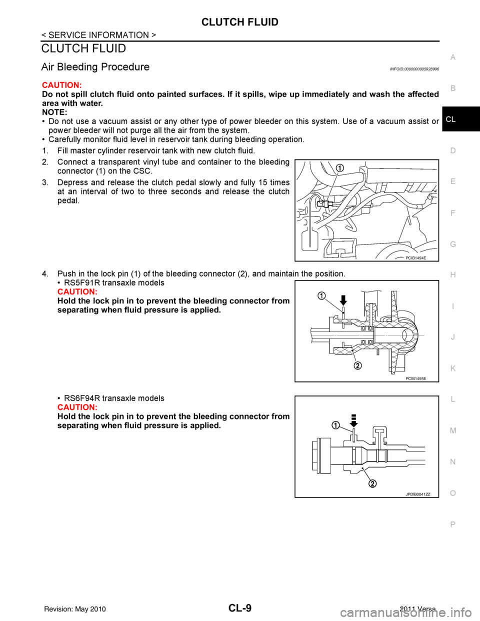
1. Clutch pedal assembly 2. Lock nut 3. Clutch interlock switch
4. ASCD clutch switch 5. Lock nut
WCIA0596E
PCIB1491E
Revision: May 2010 2011 Versa
Page 990 of 3787

CLUTCH FLUIDCL-9
< SERVICE INFORMATION >
DE
F
G H
I
J
K L
M A
B
CL
N
O P
CLUTCH FLUID
Air Bleeding ProcedureINFOID:0000000005928996
CAUTION:
Do not spill clutch fluid onto painted surfaces. If it spills, wipe up immediately and wash the affected
area with water.
NOTE:
• Do not use a vacuum assist or any other type of power bleeder on this system. Use of a vacuum assist or power bleeder will not purge all the air from the system.
• Carefully monitor fluid level in reservoir tank during bleeding operation.
1. Fill master cylinder reservoir tank with new clutch fluid.
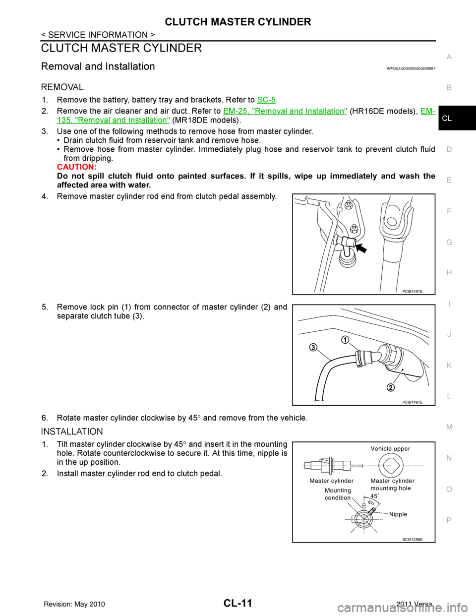
2. Connect a transparent vinyl tube and container to the bleeding connector (1) on the CSC.
3. Depress and release the clutch pedal slowly and fully 15 times at an interval of two to three seconds and release the clutch
pedal.
4. Push in the lock pin (1) of the bleeding connector (2), and maintain the position. • RS5F91R transaxle models
CAUTION:
Hold the lock pin in to preven t the bleeding connector from
separating when fluid pressure is applied.
• RS6F94R transaxle models
CAUTION:
Hold the lock pin in to preven t the bleeding connector from
separating when fluid pressure is applied.
PCIB1494E
PCIB1495E
JPDIB0041ZZ
Revision: May 2010 2011 Versa
Page 991 of 3787
CL-10
< SERVICE INFORMATION >
CLUTCH FLUID
5. Slide the clutch tube (1) in the direction of the arrow as shown tothe dimension (A). (For RS5F91R transaxle models)
2: bleeding connector
6. Slide bleeding connector (1) in the direction of the arrow as shown to the dimension (A). (For RS6F94R transaxle models)
2: clutch housing
7. Depress the clutch pedal soon and hold it, and then bleed air from the piping. wait for 5 seconds.
CAUTION:
Hold the clutch pedal down to prevent air from getting back
into the clutch system.
8. Return the clutch tube and lock pin to their original positions.
9. Release clutch pedal and wait for 5 seconds.
10. Repeat steps 3 to 8 until no bubbles are observed in the clutch fluid. Dimension (A) : 5 mm (0.20 in)
JPDIB0147ZZ
Dimension (A) : 10 mm (0.39 in)
JPDIB0042ZZ
Revision: May 2010
2011 Versa
Page 992 of 3787

CLUTCH MASTER CYLINDERCL-11
< SERVICE INFORMATION >
DE
F
G H
I
J
K L
M A
B
CL
N
O P
CLUTCH MASTER CYLINDER
Removal and InstallationINFOID:0000000005928997
REMOVAL
1. Remove the battery, battery tray and brackets. Refer to SC-5.
2. Remove the air cleaner and air duct. Refer to EM-25, "
Removal and Installation" (HR16DE models), EM-
135, "Removal and Installation" (MR18DE models).
3. Use one of the following methods to remove hose from master cylinder.
• Drain clutch fluid from reservoir tank and remove hose.
• Remove hose from master cylinder. Immediately plug hose and reservoir tank to prevent clutch fluid
from dripping.
CAUTION:
Do not spill clutch fluid onto painted surfaces. If it spills, wipe up immediately and wash the
affected area with water.
4. Remove master cylinder rod end from clutch pedal assembly.
5. Remove lock pin (1) from connector of master cylinder (2) and separate clutch tube (3).
6. Rotate master cylinder clockwise by 45 ° and remove from the vehicle.
INSTALLATION
1. Tilt master cylinder clockwise by 45° and insert it in the mounting
hole. Rotate counterclockwise to secure it. At this time, nipple is
in the up position.
2. Install master cylinder rod end to clutch pedal.
PCIB1491E
PCIB1497E
SCIA1286E
Revision: May 2010 2011 Versa
Page 993 of 3787
CL-12
< SERVICE INFORMATION >
CLUTCH MASTER CYLINDER
3. Install clutch tube (1) fully into connector of master cylinder (2).
4. Install lock pin (3) fully into connector of master cylinder (2).
5. Fill with new clutch fluid and bleed air from the system. Refer toCL-9
.
6. After completing this procedure, inspect clutch pedal operation. Refer to CL-6, "
On-vehicle Inspection and Adjustment".
7. Install the air cleaner and air duct. Refer to EM-25, "
Removal
and Installation" (HR16DE models), EM-135, "Removal and
Installation" (MR18DE models).
8. Install the battery. Refer to SC-5
.PCIB1500E
Revision: May 2010 2011 Versa
Page 996 of 3787

CLUTCH PIPINGCL-15
< SERVICE INFORMATION >
DE
F
G H
I
J
K L
M A
B
CL
N
O P
CLUTCH PIPING
Removal and InstallationINFOID:0000000005929000
Carefully observe the following steps during clutch tube removal and installation.
CAUTION:
Do not spill clutch fluid onto painted surfaces. If it spills, wipe up immediately and wash the affected
area with water.
REMOVAL
1. Remove the battery, battery tray and brackets. Refer to SC-5.
2. Remove the air cleaner and air duct. Refer to EM-25, "
Removal and Installation" (HR16DE models), EM-
135, "Removal and Installation" (MR18DE models).
3. Use one of the following methods to remove hose from clutch master cylinder. • Drain clutch fluid from reservoir tank and remove hose.
• Remove hose from clutch master cylinder. Immediat ely plug hose and reservoir tank to prevent clutch
fluid from dripping.
CAUTION:
Do not spill clutch fluid onto painted surfaces. If it spills, wipe up immediately and wash the
affected area with water.
4. Remove clutch tube lock pin from clutch master cylinder.
5. Remove clutch tube lock pin at clutch housing.
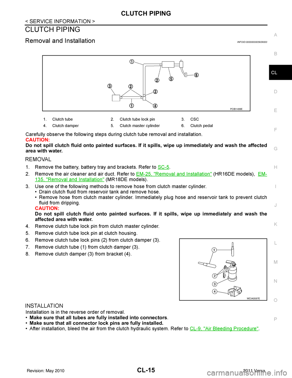
6. Remove clutch tube lock pins (2) from clutch damper (3).
7. Remove clutch tube (1) from clutch damper (3).
8. Remove clutch damper (3) from bracket (4).
INSTALLATION
Installation is in the reverse order of removal.
• Make sure that all tubes are fu lly installed into connectors.
• Make sure that all connector lock pins are fully installed.
• After installation, bleed the air from the clutch hydraulic system. Refer to CL-9, "
Air Bleeding Procedure".
1. Clutch tube2. Clutch tube lock pin 3. CSC
4. Clutch damper 5. Clutch master cylinder 6. Clutch pedal
PCIB1499E
WCIA0597E
Revision: May 2010 2011 Versa
Page 1000 of 3787

SERVICE DATA AND SPECIFICATIONS (SDS)CL-19
< SERVICE INFORMATION >
DE
F
G H
I
J
K L
M A
B
CL
N
O P
SERVICE DATA AND SPECIFICATIONS (SDS)
Clutch Control SystemINFOID:0000000005929002
Clutch PedalINFOID:0000000005929003
Clutch DiscINFOID:0000000005929004
Clutch CoverINFOID:0000000005929005
Type of clutch control Hydraulic
Clearance between clutch pedal and ASCD switch threaded end
while clutch pedal is fully released (if equipped). 0.74 - 1.96 mm (0.0291 - 0.0772 in)
Clearance between clutch pedal and clutch interlock switch
threaded end while clutch pedal is fully depressed. 0.74 - 1.96 mm (0.0291 - 0.0772 in)
Engine type
HR16DEMR18DE
Model 200225
Facing size (outer dia. × inner dia. × thickness) 200 mm x 140 mm x 3.1 mm (7.87 in x
5.51 in x 0.122 in) 225 mm ×
160 mm × 3.2 mm (8.86 in ×
6.30 in × 0.126 in)
Thickness of disc assembly with load 7.1 - 7.5 mm (0.280 - 0.295 in) with 4,658
N (475 kg, 1,047 lb) 7.2 - 7.6 mm (0.283 - 0.299 in) with
5,394 N (550 kg, 1,213 lb)
Runout limit/diameter of the area to be measured 1.0 mm (0.039 in) / 190 mm (7.48 in) dia 1.0 mm (0.039 in) / 215 mm (8.46 in)
dia.
Maximum spline backlash (at outer edge of disc) 0.8 mm (0.031 in)0.9 mm (0.035 in)
Wear limit of facing (depth to the rivet head) 0.3 mm (0.012 in)0.3 mm (0.012 in)
Engine type HR16DEMR18DE
Set-load 4,658 N (475.1 kg, 1,047.1 lb) 5,394 N (550 kg, 1,213 lb)
Diaphragm spring lever height 29 - 31 mm (1.14 - 1.22 in)20 - 22 mm (0.79 - 0.87 in)
Uneven limit of diaphragm spring toe height 0.7 mm (0.028 in) or less0.7 mm (0.028 in) or less
Revision: May 2010 2011 Versa
Page 1076 of 3787
![NISSAN TIIDA 2011 Service Repair Manual CVT SYSTEMCVT-21
< SERVICE INFORMATION > [RE0F08B]
D
E
F
G H
I
J
K L
M A
B
CVT
N
O P
Hydraulic Control SystemINFOID:0000000005928735
TCM FunctionINFOID:0000000005928736
The function of the TCM is to:
NISSAN TIIDA 2011 Service Repair Manual CVT SYSTEMCVT-21
< SERVICE INFORMATION > [RE0F08B]
D
E
F
G H
I
J
K L
M A
B
CVT
N
O P
Hydraulic Control SystemINFOID:0000000005928735
TCM FunctionINFOID:0000000005928736
The function of the TCM is to:](/manual-img/5/57396/w960_57396-1075.png)
CVT SYSTEMCVT-21
< SERVICE INFORMATION > [RE0F08B]
D
E
F
G H
I
J
K L
M A
B
CVT
N
O P
Hydraulic Control SystemINFOID:0000000005928735
TCM FunctionINFOID:0000000005928736
The function of the TCM is to:
• Receive input signals sent from various switches and sensors.
• Determine required line pressure, shifting point, and lock-up operation.
• Send required output signals to the step motor and the respective solenoids.
CONTROL SYSTEM OUTLINE
The CVT senses vehicle operating conditions through various sensors. It always controls the optimum shift
position and reduces shifting and lock-up shocks.
AWDIA0768GB
SENSORS (or SIGNAL)
⇒TCM
⇒ACTUATORS
Transmission range switch
Accelerator pedal position signal
Closed throttle position signal
Engine speed signal
CVT fluid temperature sensor
Vehicle speed signal
Overdrive control signal
Stop lamp switch signal
Primary speed sensor
Secondary speed sensor
Secondary pressure sensor Shift control
Line pressure control
Primary pressure control
Secondary pressure control
Lock-up control
Engine brake control
Vehicle speed control
Fail-safe control
Self-diagnosis
CONSULT-III co
mmunication
line
Duet-EA control
CAN system
On board diagnosis Step motor
Torque converter clutch solenoid
valve
Lock-up select solenoid valve
Line pressure solenoid valve
Secondary pressure solenoid
valve
Shift position indicator
O/D OFF indicator lamp
Starter relay
Revision: May 2010
2011 Versa