2011 NISSAN TIIDA Clutch pedal
[x] Cancel search: Clutch pedalPage 208 of 3787
TROUBLE DIAGNOSIS FOR SYMPTOMSAT-191
< SERVICE INFORMATION >
DE
F
G H
I
J
K L
M A
B
AT
N
O P
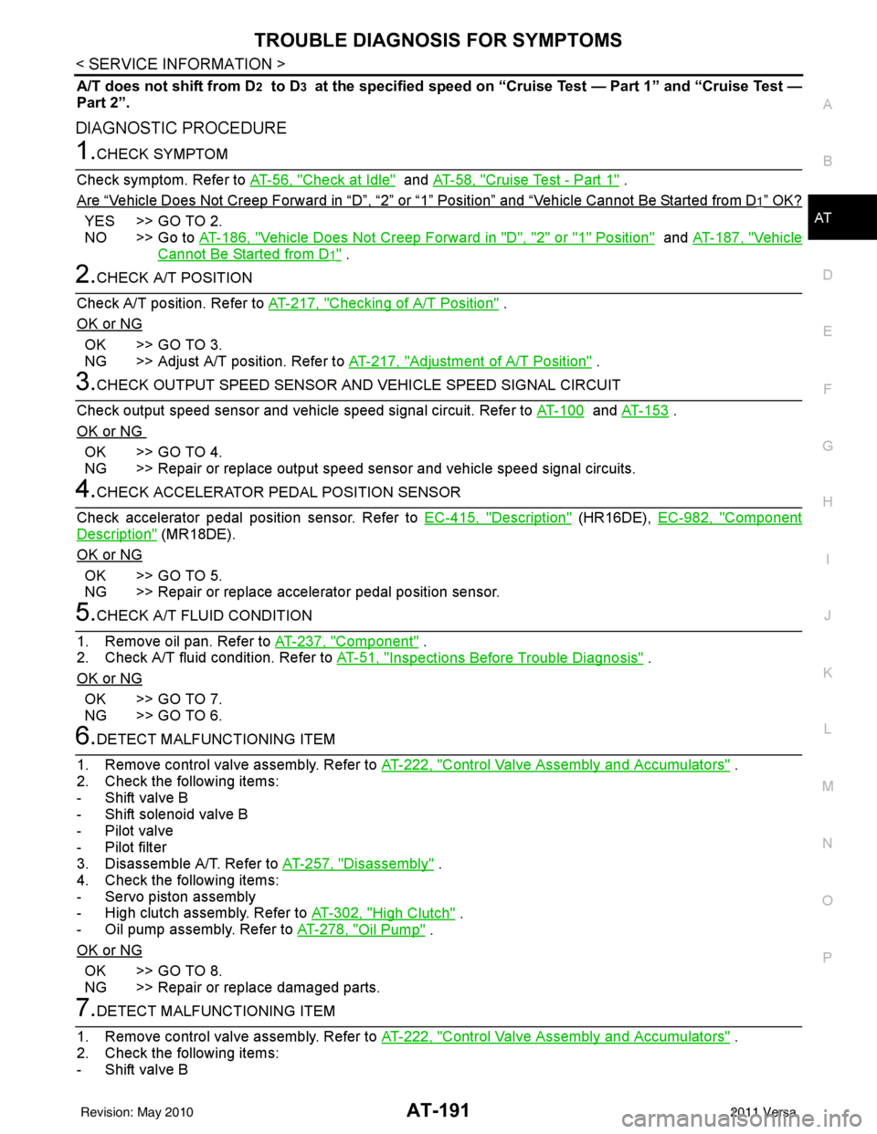
A/T does not shift from D2 to D3 at the specified speed on “Cruise Test — Part 1” and “Cruise Test —
Part 2”.
DIAGNOSTIC PROCEDURE
1.CHECK SYMPTOM
Check symptom. Refer to AT-56, "
Check at Idle" and AT-58, "Cruise Test - Part 1" .
Are
“Vehicle Does Not Creep Forward in “D”, “2” or “1” Position” and “Vehicle Cannot Be Started from D1” OK?
YES >> GO TO 2.
NO >> Go to AT-186, "
Vehicle Does Not Creep Forward in "D", "2" or "1" Position" and AT-187, "Vehicle
Cannot Be Started from D1" .
2.CHECK A/T POSITION
Check A/T position. Refer to AT-217, "
Checking of A/T Position" .
OK or NG
OK >> GO TO 3.
NG >> Adjust A/T position. Refer to AT-217, "
Adjustment of A/T Position" .
3.CHECK OUTPUT SPEED SENSOR AND VEHICLE SPEED SIGNAL CIRCUIT
Check output speed sensor and vehicle speed signal circuit. Refer to AT-100
and AT-153 .
OK or NG
OK >> GO TO 4.
NG >> Repair or replace output speed sensor and vehicle speed signal circuits.
4.CHECK ACCELERATOR PEDAL POSITION SENSOR
Check accelerator pedal position sensor. Refer to EC-415, "
Description" (HR16DE), EC-982, "Component
Description" (MR18DE).
OK or NG
OK >> GO TO 5.
NG >> Repair or replace accelerator pedal position sensor.
5.CHECK A/T FLUID CONDITION
1. Remove oil pan. Refer to AT-237, "
Component" .
2. Check A/T fluid condition. Refer to AT-51, "
Inspections Before Trouble Diagnosis" .
OK or NG
OK >> GO TO 7.
NG >> GO TO 6.
6.DETECT MALFUNCTIONING ITEM
1. Remove control valve assembly. Refer to AT-222, "
Control Valve Assembly and Accumulators" .
2. Check the following items:
- Shift valve B
- Shift solenoid valve B
- Pilot valve
- Pilot filter
3. Disassemble A/T. Refer to AT-257, "
Disassembly" .
4. Check the following items:
- Servo piston assembly
- High clutch assembly. Refer to AT-302, "
High Clutch" .
- Oil pump assembly. Refer to AT-278, "
Oil Pump" .
OK or NG
OK >> GO TO 8.
NG >> Repair or replace damaged parts.
7.DETECT MALFUNCTIONING ITEM
1. Remove control valve assembly. Refer to AT-222, "
Control Valve Assembly and Accumulators" .
2. Check the following items:
- Shift valve B
Revision: May 2010 2011 Versa
Page 211 of 3787
AT-194
< SERVICE INFORMATION >
TROUBLE DIAGNOSIS FOR SYMPTOMS
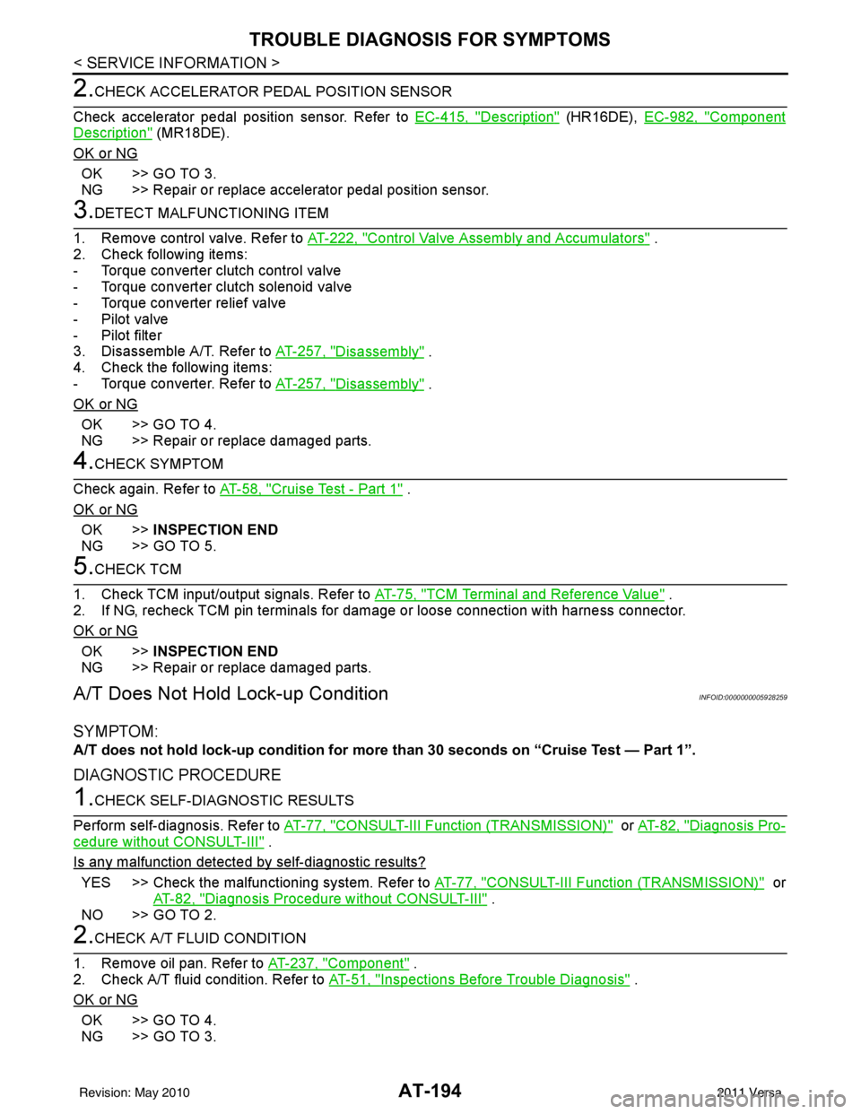
2.CHECK ACCELERATOR PEDAL POSITION SENSOR
Check accelerator pedal position sensor. Refer to EC-415, "
Description" (HR16DE), EC-982, "Component
Description" (MR18DE).
OK or NG
OK >> GO TO 3.
NG >> Repair or replace accelerator pedal position sensor.
3.DETECT MALFUNCTIONING ITEM
1. Remove control valve. Refer to AT-222, "
Control Valve Assembly and Accumulators" .
2. Check following items:
- Torque converter clutch control valve
- Torque converter clutch solenoid valve
- Torque converter relief valve
- Pilot valve
- Pilot filter
3. Disassemble A/T. Refer to AT-257, "
Disassembly" .
4. Check the following items:
- Torque converter. Refer to AT-257, "
Disassembly" .
OK or NG
OK >> GO TO 4.
NG >> Repair or replace damaged parts.
4.CHECK SYMPTOM
Check again. Refer to AT-58, "
Cruise Test - Part 1" .
OK or NG
OK >> INSPECTION END
NG >> GO TO 5.
5.CHECK TCM
1. Check TCM input/output signals. Refer to AT-75, "
TCM Terminal and Reference Value" .
2. If NG, recheck TCM pin terminals for damage or loose connection with harness connector.
OK or NG
OK >> INSPECTION END
NG >> Repair or replace damaged parts.
A/T Does Not Hold Lock-up ConditionINFOID:0000000005928259
SYMPTOM:
A/T does not hold lock-up condi tion for more than 30 seconds on “Cruise Test — Part 1”.
DIAGNOSTIC PROCEDURE
1.CHECK SELF-DIAGNOSTIC RESULTS
Perform self-diagnosis. Refer to AT-77, "
CONSULT-III Function (TRANSMISSION)" or AT-82, "Diagnosis Pro-
cedure without CONSULT-III" .
Is any malfunction detected by self-diagnostic results?
YES >> Check the malfunctioning system. Refer to AT-77, "CONSULT-III Function (TRANSMISSION)" or
AT-82, "
Diagnosis Procedure without CONSULT-III" .
NO >> GO TO 2.
2.CHECK A/T FLUID CONDITION
1. Remove oil pan. Refer to AT-237, "
Component" .
2. Check A/T fluid condition. Refer to AT-51, "
Inspections Before Trouble Diagnosis" .
OK or NG
OK >> GO TO 4.
NG >> GO TO 3.
Revision: May 2010 2011 Versa
Page 213 of 3787

AT-196
< SERVICE INFORMATION >
TROUBLE DIAGNOSIS FOR SYMPTOMS
OK >>INSPECTION END
NG >> GO TO 3.
3.CHECK TCM
1. Check TCM input/output signals. Refer to AT-75, "
TCM Terminal and Reference Value" .
2. If NG, recheck TCM pin terminals for damage or loose connection with harness connector.
OK or NG
OK >> INSPECTION END
NG >> Repair or replace damaged parts.
Engine Speed Does Not Return to Idle (Light Braking D4→ D3)INFOID:0000000005928261
SYMPTOM:
Engine speed does not smoothly return to idle when A/T shifts from D4 to D3 on “Cruise Test — Part
1”.
DIAGNOSTIC PROCEDURE
1.CHECK SELF-DIAGNOSTIC RESULTS
Perform self-diagnosis. Refer to AT-77, "
CONSULT-III Function (TRANSMISSION)" or AT-82, "Diagnosis Pro-
cedure without CONSULT-III" .
Is any malfunction detected by self-diagnostic results?
YES >> Check the malfunctioning system. Refer to AT-77, "CONSULT-III Function (TRANSMISSION)" or
AT-82, "
Diagnosis Procedure without CONSULT-III" .
NO >> GO TO 2.
2.CHECK ACCELERATOR PEDAL POSITION SENSOR
Check accelerator pedal position sensor. Refer to EC-415, "
Description" (HR16DE), EC-982, "Component
Description" (MR18DE).
OK or NG
OK >> GO TO 3.
NG >> Repair or replace accelerator pedal position sensor.
3.CHECK A/T FLUID CONDITION
1. Remove oil pan. Refer to AT-237, "
Component" .
2. Check A/T fluid condition. Refer to AT-51, "
Inspections Before Trouble Diagnosis" .
OK or NG
OK >> GO TO 5.
NG >> GO TO 4.
4.DETECT MALFUNCTIONING ITEM
1. Remove control valve assembly. Refer to AT-222, "
Control Valve Assembly and Accumulators" .
2. Check the following items:
- Overrun clutch control valve
- Overrun clutch reducing valve
- Overrun clutch solenoid valve
3. Disassemble A/T. Refer to AT-257, "
Disassembly" .
4. Check the following items:
- Overrun clutch assembly. Refer to AT-307, "
Forward and Overrun Clutches" .
OK or NG
OK >> GO TO 6.
NG >> Repair or replace damaged parts.
5.DETECT MALFUNCTIONING ITEM
1. Remove control valve assembly. Refer to AT-222, "
Control Valve Assembly and Accumulators" .
2. Check the following items:
- Overrun clutch control valve
- Overrun clutch reducing valve
- Overrun clutch solenoid valve
Revision: May 2010 2011 Versa
Page 851 of 3787
BR-4
< SERVICE INFORMATION >
PREPARATION
PREPARATION
Special Service ToolINFOID:0000000005928388
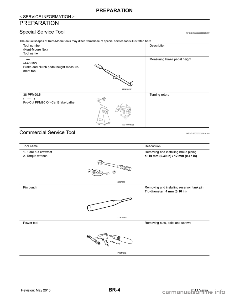
The actual shapes of Kent-Moore tools may differ from those of special service tools illustrated here.
Commercial Service ToolINFOID:0000000005928389
Tool number
(Kent-Moore No.)
Tool name Description
—
(J-46532)
Brake and clutch pedal height measure-
ment tool Measuring brake pedal height
38-PFM90.5
(—)
Pro-Cut PFM90 On-Car Brake Lathe Turning rotors
LFIA0227E
ALFIA0092ZZ
Tool name
Description
1. Flare nut crowfoot
2. Torque wrench Removing and installing brake piping
a: 10 mm (0.39 in) / 12 mm (0.47 in)
Pin punch Removing and installing reservoir tank pin
Tip diameter: 4 mm (0.16 in)
Power tool Removing nuts, bolts and screws
S-NT360
ZZA0515D
PIIB1407E
Revision: May 2010 2011 Versa
Page 982 of 3787

CL-1
TRANSMISSION/TRANSAXLE
DE
F
G H
I
J
K L
M
SECTION CL
A
B
CL
N
O P
CONTENTS
CLUTCH
SERVICE INFORMATION .. ..........................2
PRECAUTIONS .............................................. .....2
Precaution for Supplemental Restraint System
(SRS) "AIR BAG" and "SEAT BELT PRE-TEN-
SIONER" ............................................................. ......
2
Precaution Necessary for Steering Wheel Rota-
tion After Battery Disconnect ............................... ......
2
Precaution for Procedure without Cowl Top Cover ......3
Service Notice or Precaution .....................................3
PREPARATION ...................................................4
Special Service Tool ........................................... ......4
Commercial Service Tool ..........................................4
NOISE, VIBRATION AND HARSHNESS
(NVH) TROUBLESHOOTING .............................
5
NVH Troubleshooting Chart ................................ ......5
CLUTCH PEDAL .................................................6
On-vehicle Inspection and Adjustment ......................6
Removal and Installation ...........................................7
CLUTCH FLUID .................................................9
Air Bleeding Procedure ........................................ .....9
CLUTCH MASTER CYLINDER ........................11
Removal and Installation .........................................11
CSC (CONCENTRIC SLAVE CYLINDER) .......13
Exploded View .........................................................13
Removal and Installation .........................................13
CLUTCH PIPING ...............................................15
Removal and Installation .........................................15
CLUTCH DISC, CLUTCH COVER AND FLY-
WHEEL ..............................................................
16
Removal and Installation .........................................16
SERVICE DATA AND SPECIFICATIONS
(SDS) .................................................................
19
Clutch Control System .............................................19
Clutch Pedal ............................................................19
Clutch Disc ..............................................................19
Clutch Cover ............................................................19
Revision: May 2010 2011 Versa
Page 986 of 3787

NOISE, VIBRATION AND HARSHNESS (NVH) TROUBLESHOOTINGCL-5
< SERVICE INFORMATION >
DE
F
G H
I
J
K L
M A
B
CL
N
O P
NOISE, VIBRATION AND HARSHN ESS (NVH) TROUBLESHOOTING
NVH Troubleshooting ChartINFOID:0000000005928993
Use the chart below to help you find the cause of the symptom. The numbers indicate the order of the inspec-
tion. If necessary, repair or replace these parts.
Reference pageCL-6CL-9EM-197CL-13CL-16EM-219
SUSPECTED PARTS (Possible cause)
CLUTCH PEDAL (Inspection and adjustment)
CLUTCH LINE (Air in line)
ENGINE MOUNTING (Loose)
CSC (Concentric slave cylinder) (Worn, dirty or damaged)
CLUTCH DISC (Out of true)
CLUTCH DISC (Runou t is excessive)
CLUTCH DISC (Lining broken)
CLUTCH DISC (Dirty or burned)
CLUTCH DISC (Oily)
CLUTCH DISC (Worn out)
CLUTCH DISC (Hardened)
CLUTCH DISC (Lack of spline grease)
DIAPHRAGM SPRING (Damaged)
DIAPHRAGM SPRING (Out of tip alignment)
PRESSURE PLATE (Distortion)
FLYWHEEL (Distortion)
Symptom Clutch grabs/chatters
122 2 2 2
Clutch pedal spongy 1
Clutch noisy 1
Clutch slips 1 2 23 4 5
Clutch does not disengage 12 55555 5667
Revision: May 2010 2011 Versa
Page 987 of 3787
CL-6
< SERVICE INFORMATION >
CLUTCH PEDAL
CLUTCH PEDAL
On-vehicle Inspection and AdjustmentINFOID:0000000005928994
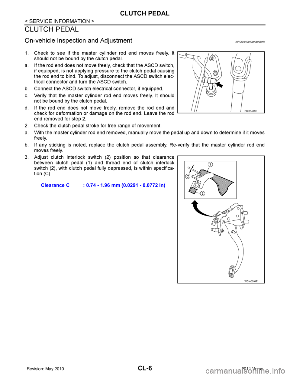
1. Check to see if the master cylinder rod end moves freely. Itshould not be bound by the clutch pedal.
a. If the rod end does not move freely, check that the ASCD switch, if equipped, is not applying pressure to the clutch pedal causing
the rod end to bind. To adjust, disconnect the ASCD switch elec-
trical connector and turn the ASCD switch.
b. Connect the ASCD switch electrical connector, if equipped.
c. Verify that the master cylinder rod end moves freely. It should not be bound by the clutch pedal.
d. If the rod end does not move freely, remove the rod end and check for deformation or damage on the rod end. Leave the rod
end removed for step 2.
2. Check the clutch pedal stroke for free range of movement.
a. With the master cylinder rod end removed, manually move the pedal up and down to determine if it moves
freely.
b. If any sticking is noted, replace the clutch pedal assembly. Re-verify that the master cylinder rod end
moves freely.
3. Adjust clutch interlock switch (2) position so that clearance between clutch pedal (1) and thread end of clutch interlock
switch (2), with clutch pedal fully depressed, is within specifica-
tion (C).
Clearance C : 0.74 - 1.96 mm (0.0291 - 0.0772 in)
PCIB1491E
WCIA0594E
Revision: May 2010 2011 Versa
Page 988 of 3787
CLUTCH PEDALCL-7
< SERVICE INFORMATION >
DE
F
G H
I
J
K L
M A
B
CL
N
O P
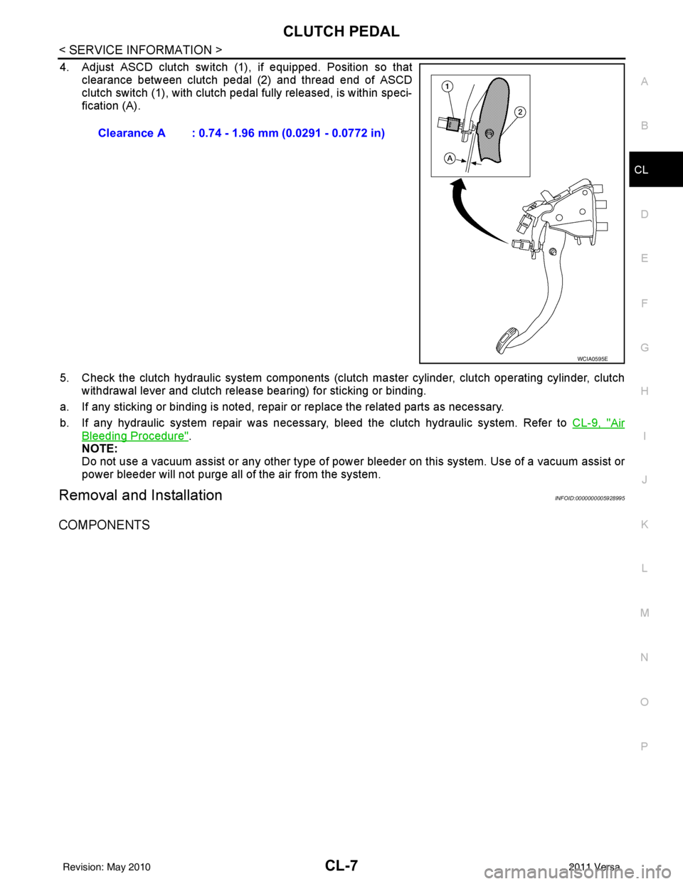
4. Adjust ASCD clutch switch (1 ), if equipped. Position so that
clearance between clutch pedal (2) and thread end of ASCD
clutch switch (1), with clutch pedal fully released, is within speci-
fication (A).
5. Check the clutch hydraulic system components (clutc h master cylinder, clutch operating cylinder, clutch
withdrawal lever and clutch release bearing) for sticking or binding.
a. If any sticking or binding is noted, repair or replace the related parts as necessary.
b. If any hydraulic system repair was necessary, bleed the clutch hydraulic system. Refer to CL-9, "
Air
Bleeding Procedure".
NOTE:
Do not use a vacuum assist or any other type of power bleeder on this system. Us e of a vacuum assist or
power bleeder will not purge all of the air from the system.
Removal and InstallationINFOID:0000000005928995
COMPONENTS
Clearance A : 0.74 - 1.96 mm (0.0291 - 0.0772 in)
WCIA0595E
Revision: May 2010 2011 Versa