2011 NISSAN TIIDA door
[x] Cancel search: doorPage 3178 of 3787
GENERAL MAINTENANCEMA-7
< SERVICE INFORMATION >
C
DE
F
G H
I
J
K
M A
B
MA
N
O P
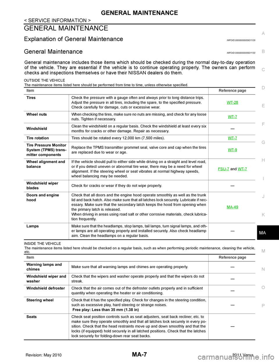
GENERAL MAINTENANCE
Explanation of Gene ral MaintenanceINFOID:0000000005931129
General MaintenanceINFOID:0000000005931130
General maintenance includes those items which shoul d be checked during the normal day-to-day operation
of the vehicle. They are essential if the vehicle is to continue operating properly. The owners can perform
checks and inspections themselves or have their NISSAN dealers do them.
OUTSIDE THE VEHICLE
The maintenance items listed here should be performed from time to time, unless otherwise specified.
INSIDE THE VEHICLE The maintenance items listed here should be checked on a regular basis, such as when performing periodic maintenance, cleaning the vehicle,
etc.
Item Reference page
Tires Check the pressure with a gauge often and always prior to long distance trips.
Adjust the pressure in all tires, including the spare, to the specified pressure.
Check carefully for damage, cuts or excessive wear. WT-28
Wheel nuts
When checking the tires, make sure no nuts are missing, and check for any loose
nuts. Tighten if necessary. WT-7
WindshieldClean the windshield on a regular basis. Check the windshield at least every six
months for cracks or other damage. Repair as necessary.
—
Tire rotation Tires should be rotated every 12,000 km (7,500 miles). WT-7
Tire Pressure Monitor
System (TPMS) trans-
mitter componentsReplace the TPMS transmitter grommet seal, valve core and cap when the tires
are replaced due to wear or age.
WT-9
Wheel alignment and
balanceIf the vehicle should pull to either side while driving on a straight and level road,
or if you detect uneven or abnormal tire wear, there may be a need for wheel
alignment. If the steering wheel or seat vibrates at normal highway speeds,
wheel balancing may be needed. FSU-7
and
WT-7
Windshield wiper
blades Check for cracks or wear if they do not wipe properly.
—
Doors and engine
hood Check that all doors and the engine hood operate smoothly as well as the trunk
lid and back hatch. Also make sure that all latches lock securely. Lubricate if nec-
essary. Make sure that the secondary latch keeps the hood from opening when
the primary latch is released.
When driving in areas using road salt or other corrosive materials, check lubrica-
tion frequently. MA-49
Lamps
Make sure that the headlamps, stop lamps, tail lamps, turn signal lamps, and oth-
er lamps are all operating properly and installed securely. Also check headlamp
aim. Clean the headlamps on a regular basis. —
Item
Reference page
Warning lamps and
chimes Make sure that all warning lamps and chimes are operating properly.
—
Windshield wiper and
washer Check that the wipers and washer operate properly and that the wipers do not
streak.
—
Windshield defroster Check that the air comes out of the defroster outlets properly and in sufficient
quantity when operating the heater or air conditioning. —
Steering wheel Check that it has the specified play. Check for changes in the steering condition,
such as excessive play, hard steering or strange noises.
Free play: Less than 35 mm (1.38 in) —
Seats Check seat position controls such as seat adjusters, seat back recliner, etc. to
make sure they operate smoothly and that all latches lock securely in every po-
sition. Check that the head restraints move up and down smoothly and that the
locks (if equipped) hold securely in all latched positions. Check that the latches
lock securely for folding-down rear seat backs. —
Revision: May 2010
2011 Versa
Page 3180 of 3787

PERIODIC MAINTENANCEMA-9
< SERVICE INFORMATION >
C
DE
F
G H
I
J
K
M A
B
MA
N
O P
PERIODIC MAINTENANCE
Introduction of Periodic MaintenanceINFOID:0000000005931131
Two different maintenance schedules are provi ded, and should be used, depending upon the conditions in
which the vehicle is mainly operated. After 60,000 miles (96,000 km) or 48 months, continue the periodic
maintenance at the same mileage/time intervals.
Schedule 1INFOID:0000000005931132
Emission Control System Maintenance
Abbreviations: R = Replace. I = Inspect. Correct or r eplace if necessary. [ ]: At the mileage intervals only
Schedule 1Follow Periodic Maintenance Schedule 1 if your driving habits frequently includes
one or more of the following driving conditions:
• Repeated short trips of less than 5 miles (8 km).
• Repeated short trips of less than 10 miles (16 km) with outside temperatures re-
maining below freezing.
• Operating in hot weather in stop-and-go “rush hour” traffic.
• Extensive idling and/or low speed driving for long distances, such as police, taxi
or door-to-door delivery use.
• Driving in dusty conditions.
• Driving on rough, muddy, or salt spread roads.
• Towing a trailer, using a camper or a car-top carrier. Emission Control Sys-
tem Maintenance
MA-9
Chassis and Body
Maintenance
MA-9
Schedule 2Follow Periodic Maintenance Schedule 2 if none of the driving conditions shown
in Schedule 1 apply to your driving habits.
Emission Control Sys-
tem Maintenance
MA-11Chassis and Body
Maintenance
MA-11
MAINTENANCE OPERATION
MAINTENANCE INTERVAL
Reference Section -
Page or - Content Title
Perform at number of
miles, kilometers or
months, whichever
comes first. Miles x 1,000
(km x 1,000) Months 3.75
(6)3 7.5
(12) 6 11 . 2 5
(18) 9 15
(24) 12 18.75
(30)15 22.5
(36) 18 26.25
(42)21 30
(48) 24
Drive belt NOTE (1) MA-16
(HR)
MA-26
(MR)
Air cleaner filter NOTE (2) [R]EM-13
(HR)
EM-136
(MR)
EVAP vapor lines I*MA-25
(HR)
MA-36
(MR)
Fuel lines I*FL-5
Fuel filter NOTE (3) —
Engine coolant* NOTE (4) CO-11
(HR)
CO-36
(MR)
Engine oil R R R R R R R R LU-8
(HR)
LU-18
(MR)
Engine oil filter (Use
genuine oil filter or
equivalent) RRRRRRRR
LU-9
(HR)
LU-20
(MR)
Spark plugs (Iridium/
platinum - tipped
type) Replace every 105,000 miles (168,000 km)
EM-17
(HR)
EM-151
(MR)
Intake and exhaust
valve clearance* NOTE (5) EM-114
(HR)
EM-230
(MR)
Revision: May 2010 2011 Versa
Page 3317 of 3787

MTC-1
AIR CONDITIONER
C
DE
F
G H
I
K L
M
SECTION MTC
A
B
MTC
N
O P
CONTENTS
MANUAL AIR CONDITIONER
SERVICE INFORMATION .. ..........................3
PRECAUTIONS .............................................. .....3
Precaution for Supplemental Restraint System
(SRS) "AIR BAG" and "SEAT BELT PRE-TEN-
SIONER" ............................................................. ......
3
Precaution Necessary for Steering Wheel Rota-
tion After Battery Disconnect ............................... ......
3
Precaution for Procedure without Cowl Top Cover ......4
Precaution for Working with HFC-134a (R-134a) ......4
General Refrigerant Precaution ................................4
Oil Precaution ............................................................5
Precaution for Refrigerant Connection ......................5
Precaution for Service of Compressor ................ ......8
Precaution for Service Equipment ....................... ......8
Precaution for Leak Detection Dye ...........................9
PREPARATION ..................................................11
HFC-134a (R-134a) Service Tool and Equipment ....11
Commercial Service Tool ........................................14
REFRIGERATION SYSTEM ..............................15
Refrigerant Cycle ................................................ ....15
Refrigerant System Protection ................................15
Component Part Location ................................... ....16
OIL ......................................................................17
Maintenance of Oil Quantity in Compressor ....... ....17
AIR CONDITIONER CONTROL .........................19
Control Operation ................................................ ....19
Discharge Air Flow ..................................................20
System Description .................................................20
TROUBLE DIAGNOSIS .....................................22
CONSULT-III Function (BCM) ............................. ....22
How to Perform Trouble Diagnosis for Quick and
Accurate Repair ......................................................
23
Component Parts and Harness Connector Loca-
tion ...................................................................... ....
23
Schematic ...............................................................26
Wiring Diagram - Heater - .......................................27
Wiring Diagram - A/C,M - .................................... ....28
Operational Check ...................................................31
Mode Door ...............................................................32
Air Mix Door .............................................................33
Intake Door ..............................................................34
Front Blower Motor Circuit .......................................34
Magnet Clutch Circuit (If Equipped) ..................... ....38
Insufficient Cooling ..................................................46
Insufficient Heating ..................................................53
Noise .......................................................................54
CONTROLLER ..................................................56
Removal and Installation .........................................56
Disassembly and Assembly .....................................57
THERMO CONTROL AMPLIFIER ....................58
Removal and Installation .........................................58
A/C UNIT ASSEMBLY ......................................59
Removal and Installation .........................................59
Disassembly and Assembly .....................................61
BLOWER MOTOR ............................................63
Removal and Installation .........................................63
INTAKE DOOR ..................................................64
Intake Door Cable Adjustment .................................64
AIR MIX DOOR .................................................65
Air Mix Door Cable Adjustment ...............................65
MODE DOOR ....................................................66
Mode Door Cable Adjustment .................................66
BLOWER FAN RESISTOR ...............................67
Removal and Installation .........................................67
HEATER CORE .................................................68
Removal and Installation .........................................68
DUCTS AND GRILLES .....................................69
Removal and Installation .........................................69
Revision: May 2010 2011 Versa
Page 3335 of 3787
AIR CONDITIONER CONTROLMTC-19
< SERVICE INFORMATION >
C
DE
F
G H
I
K L
M A
B
MTC
N
O P
AIR CONDITIONER CONTROL
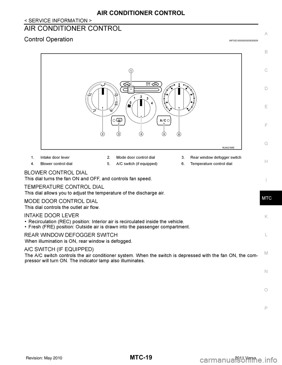
Control OperationINFOID:0000000005930839
BLOWER CONTROL DIAL
This dial turns the fan ON and OFF, and controls fan speed.
TEMPERATURE CONTROL DIAL
This dial allows you to adjust the temperature of the discharge air.
MODE DOOR CONTROL DIAL
This dial controls the outlet air flow.
INTAKE DOOR LEVER
• Recirculation (REC) position: Interior air is recirculated inside the vehicle.
• Fresh (FRE) position: Outside air is drawn into the passenger compartment.
REAR WINDOW DEFOGGER SWITCH
When illumination is ON, rear window is defogged.
A/C SWITCH (IF EQUIPPED)
The A/C switch controls the air conditioner system. When the switch is depressed with the fan ON, the com-
pressor will turn ON. The indicator lamp also illuminates.
1. Intake door lever 2. Mode door control dial 3. Rear window defogger switch
4. Blower control dial 5. A/C switch (if equipped)6. Temperature control dial
WJIA2189E
Revision: May 2010 2011 Versa
Page 3336 of 3787
MTC-20
< SERVICE INFORMATION >
AIR CONDITIONER CONTROL
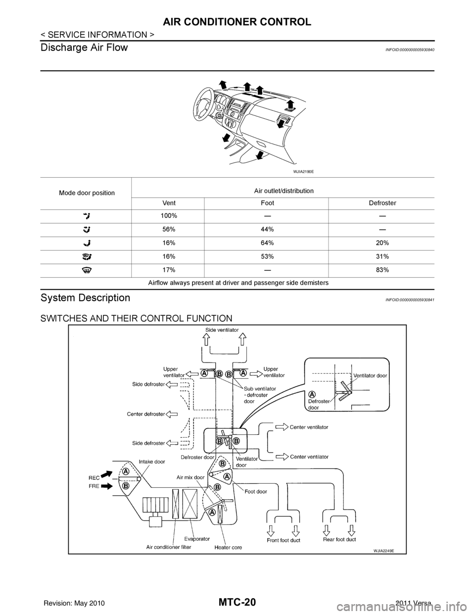
Discharge Air Flow
INFOID:0000000005930840
System DescriptionINFOID:0000000005930841
SWITCHES AND THEIR CONTROL FUNCTION
Mode door position Air outlet/distribution
Vent Foot Defroster
100% — —
56% 44% —
16% 64% 20%
16% 53% 31%
17% — 83%
Airflow always present at driver and passenger side demisters
WJIA2190E
WJIA2249E
Revision: May 2010 2011 Versa
Page 3338 of 3787

MTC-22
< SERVICE INFORMATION >
TROUBLE DIAGNOSIS
TROUBLE DIAGNOSIS
CONSULT-III Function (BCM)INFOID:0000000005930842
CONSULT-III can display each diagnostic item using the diagnostic test modes shown following.
ITEMS OF EACH PART
NOTE:
CONSULT-III will only display systems the vehicle possesses.
BCM diagnostic
test item Diagnostic mode
Content
Inspection by part WORK SUPPORT
Supports inspections and adjustments. Commands are transmitted to the BCM for
setting the status suitable for required operation, input/output signals are received
from the BCM and received data is displayed.
DATA MONITOR Displays BCM input/output data in real time. ACTIVE TEST Operation of electrical loads can be checked by sending drive signal to them.
SELF-DIAG RESULTS Displays BCM self-diagnosis results. CAN DIAG SUPPORT MNTR The results of transmit/receive diagnosis of CAN communication can be read.
ECU PART NUMBER BCM part number can be read. CONFIGURATION Performs BCM configuration read/write functions.
System and item CONSULT-III dis-
play Diagnostic test mode (Inspection by part)
WORK
SUPPORT SELF
−
DIAG RE-
SULTS CAN DIAG
SUPPORT
MNTR DATA
MONITOR ECU
PA R T
NUMBER AC-
TIVE
TEST CON-
FIGU-
RATION
BCM BCM×× × × ×
Power door lock sys-
tem DOOR LOCK
×× ×
Rear defogger REAR DEFOG-
GER ××
Warning chime BUZZER ××
Room lamp timer INT LAMP ×× ×
Remote keyless entry
system MULTI REMOTE
ENT
××
×
Headlamp HEAD LAMP×× ×
Wiper WIPER×× ×
Turn signal lamp
Hazard lamp FLASHER
××
Blower fan switch sig-
nal
Air conditioner switch
signal AIR CONDITION-
ER
×
Intelligent Key INTELLIGENT
KEY ×
Combination switch COMB SW ×
NVIS (NATS) IMMU ××
Interior lamp battery
saver BATTERY SAV-
ER
××
×
Back door/Trunk TRUNK ××
Theft alarm THEFT ALARM×× ×
Revision: May 2010 2011 Versa
Page 3339 of 3787
TROUBLE DIAGNOSISMTC-23
< SERVICE INFORMATION >
C
DE
F
G H
I
K L
M A
B
MTC
N
O P
WORK SUPPORT
Display Item List
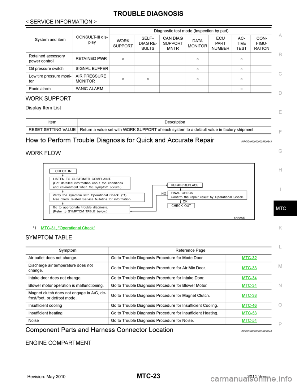
How to Perform Trouble Diagnosis for Quick and Accurate RepairINFOID:0000000005930843
WORK FLOW
SYMPTOM TABLE
Component Parts and Har ness Connector LocationINFOID:0000000005930844
ENGINE COMPARTMENT
Retained accessory
power controlRETAINED PWR
×× ×
Oil pressure switch SIGNAL BUFFER ××
Low tire pressure moni-
tor AIR PRESSURE
MONITOR
××
× ×
Panic alarm PANIC ALARM ×
System and item
CONSULT-III dis-
play Diagnostic test mode (Inspection by part)
WORK
SUPPORT SELF
−
DIAG RE-
SULTS CAN DIAG
SUPPORT
MNTR DATA
MONITOR ECU
PA R T
NUMBER AC-
TIVE
TEST CON-
FIGU-
RATION
Item Description
RESET SETTING VALUE Return a value set with WORK SUPPORT of each system to a default value in factory shipment.
*1 MTC-31, "Operational Check"
SHA900E
Symptom Reference Page
Air outlet does not change. Go to Trouble Diagnosis Procedure for Mode Door. MTC-32
Discharge air temperature does not
change.Go to Trouble Diagnosis Procedure for Air Mix Door.
MTC-33
Intake door does not change.Go to Trouble Diagnosis Procedure for Intake Door. MTC-34
Blower motor operation is malfunctioning. Go to Trouble Diagnosis Procedure for Blower Motor. MTC-34
Magnet clutch does not engage in A/C, de-
frost/foot, or defrost mode.Go to Trouble Diagnosis Procedure for Magnet Clutch.
MTC-38
Insufficient coolingGo to Trouble Diagnosis Procedure for Insufficient Cooling. MTC-46
Insufficient heatingGo to Trouble Diagnosis Procedure for Insufficient Heating. MTC-53
NoiseGo to Trouble Diagnosis Procedure for Noise. MTC-54
Revision: May 2010 2011 Versa
Page 3348 of 3787
MTC-32
< SERVICE INFORMATION >
TROUBLE DIAGNOSIS
1. Turn blower control dial clockwise to "1" position. Blower should operate on low speed.
2. Turn blower control dial clockwise to "2" position, and continue checking blower speed until all speeds are
checked.
3. Leave blower on Maximum speed.
If NG, go to trouble diagnosis procedure for MTC-34, "
Front Blower Motor Circuit".
If OK, continue the check.
CHECKING DISCHARGE AIR
1. Turn mode door control dial to each position.
2. Confirm that discharge air comes out according to the air distribution table. Refer to MTC-20, "
Discharge
Air Flow".
If NG, go to trouble diagnosis procedure for MTC-32, "
Mode Door".
If OK, continue the check.
CHECKING RECIRCULATION
1. Set intake door lever to REC position.
2. Operate intake door lever to FRE position.
3. Listen for intake door position change (you should hear blower sound change slightly).
If NG, go to trouble diagnosis procedure for MTC-34, "
Intake Door".
If OK, continue the check.
CHECKING TEMPERATURE DECREASE
1. Turn temperature control dial counterclockwise to full cold position.
2. Check for cold air at discharge air outlets.
If NG, go to trouble diagnosis procedure for MTC-46, "
Insufficient Cooling".
If OK, continue the check.
CHECKING TEMPERATURE INCREASE
1. Turn temperature control dial clockwise to full hot position.
2. Check for hot air at discharge air outlets.
If NG, go to trouble diagnosis procedure for MTC-53, "
Insufficient Heating".
If OK, continue the check.
CHECKING A/C SWITCH (IF EQUIPPED)
1. Turn fan control dial to the desired (1 to 4 speed) position.
2. Press A/C switch.
3. A/C switch indicator will turn ON.
• Confirm that the compressor clutch engages (sound or visual inspection).
If NG, go to trouble diagnosis procedure for MTC-38, "
Magnet Clutch Circuit (If Equipped)".
If OK, continue the check.
CHECKING DEFROST A/C SWITCH (IF EQUIPPED)
1. Turn fan control dial to the desired (1 to 4 speed) position.
2. Turn mode dial to ( ) DEF.
3. Confirm that the compressor clutch engages (sound or visual inspection) and the A/C switch indicator illu- minates.
If NG, go to trouble diagnosis procedure for MTC-38, "
Magnet Clutch Circuit (If Equipped)".
If all operational checks are OK (symptom cannot be duplicated), go to MTC-23, "
How to Perform Trouble
Diagnosis for Quick and Accurate Repair" and perform tests as outlined. If symptom appears, refer to MTC-23,
"How to Perform Trouble Diagnosis for Quick and Accurate Repair" and perform applicable trouble diagnosis
procedures.
Mode DoorINFOID:0000000005930849
SYMPTOM: Air outlet does not change.
INSPECTION FLOW
Revision: May 2010 2011 Versa