Page 3373 of 3787
CONTROLLERMTC-57
< SERVICE INFORMATION >
C
DE
F
G H
I
K L
M A
B
MTC
N
O P
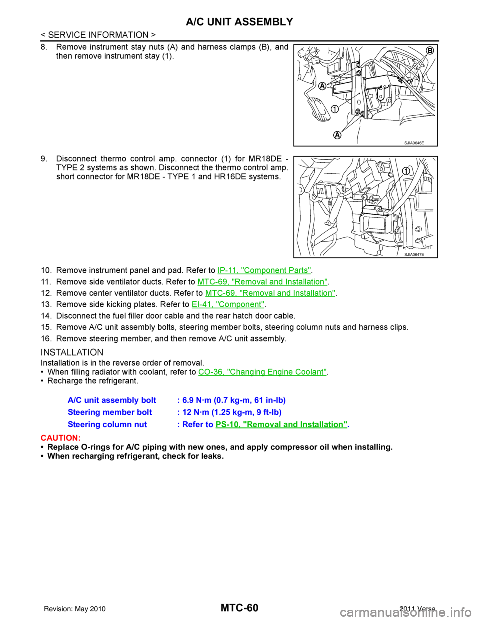
Disassembly and AssemblyINFOID:0000000005930858
CAUTION:
Install inner cable of each do or cable to the corresponding
lever, as shown in the figure. Pr ess outer cable until it hooks on
the tabs and becomes secure.
1. Air mix door cable 2. Intake door cable3. Mode door cable
4. A/C controller assembly 5. Mode control dial6. Rear DEF button
7. A/C button 8. Temperature control dial9. Illumination bulb
10. Intake door lever knob 11. Fan control dial
ZJIA0106J
MJIA0038E
Revision: May 2010 2011 Versa
Page 3376 of 3787

MTC-60
< SERVICE INFORMATION >
A/C UNIT ASSEMBLY
8. Remove instrument stay nuts (A) and harness clamps (B), andthen remove instrument stay (1).
9. Disconnect thermo control amp. connector (1) for MR18DE - TYPE 2 systems as shown. Di sconnect the thermo control amp.
short connector for MR18DE - TYPE 1 and HR16DE systems.
10. Remove instrument panel and pad. Refer to IP-11, "
Component Parts".
11. Remove side ventilator ducts. Refer to MTC-69, "
Removal and Installation".
12. Remove center ventilator ducts. Refer to MTC-69, "
Removal and Installation".
13. Remove side kicking plates. Refer to EI-41, "
Component".
14. Disconnect the fuel filler door cable and the rear hatch door cable.
15. Remove A/C unit assembly bolts, steering member bolts, steering column nuts and harness clips.
16. Remove steering member, and then remove A/C unit assembly.
INSTALLATION
Installation is in the reverse order of removal.
• When filling radiator with coolant, refer to CO-36, "
Changing Engine Coolant".
• Recharge the refrigerant.
CAUTION:
• Replace O-rings for A/C piping with new ones, and apply compressor oil when installing.
• When recharging refrigerant, check for leaks.
SJIA0646E
SJIA0647E
A/C unit assembly bolt : 6.9 N·m (0.7 kg-m, 61 in-lb)
Steering member bolt : 12 N·m (1.25 kg-m, 9 ft-lb)
Steering column nut : Refer to PS-10, "
Removal and Installation".
Revision: May 2010 2011 Versa
Page 3377 of 3787

A/C UNIT ASSEMBLYMTC-61
< SERVICE INFORMATION >
C
DE
F
G H
I
K L
M A
B
MTC
N
O P
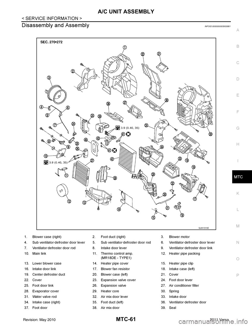
Disassembly and AssemblyINFOID:0000000005930861
1. Blower case (right) 2. Foot duct (right) 3. Blower motor
4. Sub ventilator·defroster door lever 5. Sub ventilator·defroster door rod 6. Ventilator·defroster door lever
7. Ventilator·defroster door rod 8. Intake door lever 9. Ventilator·defroster door link
10. Main link 11. Thermo control amp.
(MR18DE - TYPE1) 12. Heater pipe packing
13. Lower blower case 14. Heater pipe cover 15. Heater pipe clip
16. Intake door link 17. Blower fan resistor 18. Intake case (left)
19. Center defroster duct 20. Blower case (left) 21. Cover
22. Cover 23. Expansion valve cover 24. Foot door lever
25. Foot door link 26. Expansion valve 27. Air conditioner filter
28. Evaporator cover 29. Heater core 30. Spring
31. Water valve rod 32. Air mix door lever 33. Intake door
34. Intake case (right) 35. Foot duct (left) 36. Ventilator·defroster door
37. Foot door 38. Air mix door 39. Seal
SJIA1515E
Revision: May 2010 2011 Versa
Page 3380 of 3787
MTC-64
< SERVICE INFORMATION >
INTAKE DOOR
INTAKE DOOR
Intake Door Cable AdjustmentINFOID:0000000005930863
1. Remove instrument lower finisher. Refer to IP-11.
2. Remove outer cable of intake door cable (1) from clamp (A).
3. Set intake door lever to REC position.
4. Push intake door link (2) in the direction shown by the arrow, and then carefully pull outer cable to controller side, and install
clamp (A).
5. Operate intake door lever to insure that inner cable moves smoothly.
CAUTION:
When clamping the outer cable, do not move the inner
cable.
SJIA0650E
Revision: May 2010 2011 Versa
Page 3381 of 3787
AIR MIX DOORMTC-65
< SERVICE INFORMATION >
C
DE
F
G H
I
K L
M A
B
MTC
N
O P
AIR MIX DOOR
Air Mix Door Cable AdjustmentINFOID:0000000005930864
1. Remove steering member. Refer to MTC-59.
2. Remove outer cable of air mix door cable (1) from clamp (A).
3. Set temperature control dial to full cold position.
4. Push air mix door lever (2) in the direction shown by arrow, and then carefully pull outer cable toward controller side, and install
clamp (A).
5. Operate temperature control dial to insure that inner cable moves smoothly.
CAUTION:
When clamping the outer cab le, do not move the inner
cable.
SJIA1150E
Revision: May 2010 2011 Versa
Page 3382 of 3787
MTC-66
< SERVICE INFORMATION >
MODE DOOR
MODE DOOR
Mode Door Cable AdjustmentINFOID:0000000005930865
1. Remove glove box assembly and instrument lower cover (RH). Refer to IP-11.
2. Remove outer cable of mode door cable (1) from clamp (A).
3. Set mode control dial to VENT position.
4. Push main link (2) in the direction shown by the arrow, and then carefully pull outer cable to controller side, and install clamp (A).
5. Operate mode control dial to insure that inner cable moves smoothly.
CAUTION:
When clamping the outer cable, do not move the inner
cable.
6. Turn mode control dial to each position.
7. Confirm that discharge air comes out according to the air distribution table. Refer to MTC-20, "
Discharge
Air Flow".
SJIA0654E
Revision: May 2010 2011 Versa
Page 3411 of 3787

REFRIGERANT LINESMTC-95
< SERVICE INFORMATION >
C
DE
F
G H
I
K L
M A
B
MTC
N
O P
6. Do not stop when one leak is found. Continue to check for additional leaks at all system components.
If no leaks are found, perform steps 7-10.
7. Start engine.
8. Set the heater A/C control as follows;
a. A/C switch: ON
b. Mode control dial position: VENT (Ventilation)
c. Intake door lever position: Recirculation
d. Max. cold temperature
e. Fan speed: High
9. Run engine at 1,500 rpm for at least 2 minutes.
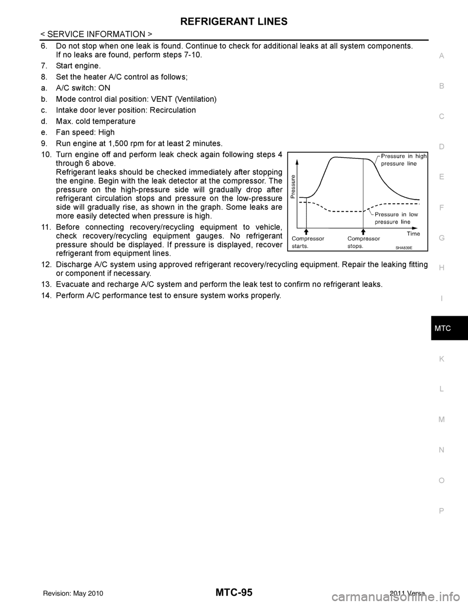
10. Turn engine off and perform leak check again following steps 4 through 6 above.
Refrigerant leaks should be chec ked immediately after stopping
the engine. Begin with the leak detector at the compressor. The
pressure on the high-pressure side will gradually drop after
refrigerant circulation stops and pressure on the low-pressure
side will gradually rise, as shown in the graph. Some leaks are
more easily detected when pressure is high.
11. Before connecting recovery/recycling equipment to vehicle, check recovery/recycling equipment gauges. No refrigerant
pressure should be displayed. If pressure is displayed, recover
refrigerant from equipment lines.
12. Discharge A/C system using approved refrigerant recovery/recycling equipment. Repair the leaking fitting or component if necessary.
13. Evacuate and recharge A/C system and perform the l eak test to confirm no refrigerant leaks.
14. Perform A/C performance test to ensure system works properly.
SHA839E
Revision: May 2010 2011 Versa
Page 3440 of 3787

PG-20
< SERVICE INFORMATION >
IPDM E/R (INTELLIGENT POWER DISTRIBUTION MODULE ENGINE ROOM)
*1 Perform monitoring of IPDM E/R data with the ignition switch ON. When the ignition switch is in ACC position, display may no t be cor-
rect.
*2 This item is displayed, but does not function.
CAN DIAG SUPPORT MNTR
Refer to LAN-9, "Description" .
ACTIVE TEST
Display Item List
Auto Active TestINFOID:0000000005928347
DESCRIPTION
• In auto active test mode, operation inspection can be performed when IPDM E/R sends a drive signal to the
following systems:
- Rear window defogger
- Front wipers
- Tail, license and parking lamps
- Daytime lamp system (Canada only)
- Front fog lamps
- Headlamps (High, Low)
- A/C compressor (magnet clutch)
- Cooling fan
OPERATION PROCEDURE
1. Close hood and front door RH, and lift wiper arms away from windshield (to prevent glass damage by wiper operation).
NOTE:
When auto active test is performed with hood opened, sprinkle water on windshield beforehand.
2. Turn ignition switch OFF.
3. Turn ignition switch ON and, within 20 seconds, pres s front door switch LH 10 times. Then turn ignition
switch OFF.
4. Turn ignition switch ON within 10 seconds after ignition switch OFF.
5. When auto active test mode is actuated, horn chirps once.
6. After a series of operations is repeated three times, auto active test is completed.
Theft warning
horn request THFT HRN REQ ON/OFF
XX Signal status input from BCM
Horn chirp HORN CHIRP ON/OFF XX Output status of IPDM E/R
Daytime light re-
quest DTRL REQ ON/OFF
XX Signal status input from BCM
Item name
CONSULT-III
screen display Display or unit Monitor item selection
Description
ALL
SIGNALS MAIN
SIGNALS SELECTION
FROM MENU
Test name CONSULT-III screen display Description
Head, tail, fog lamp output EXTERNAL LAMPS With a certain ON-OFF operation (OFF, TAIL, LO, HI, FOG), the front
fog lamp, headlamp low, headlamp high RH, headlamp high LH, and
tail lamp relays can be operated.
Rear defogger output REAR DEFOGGER With a certain ON-OFF operation, the rear defogger relay can be oper-
ated.
Front wiper (HI, LO) output FRONT WIPER With a certain operation (OFF, HI ON, LO ON), the front wiper relays
(Lo, Hi) can be operated.
Cooling fan output MOTOR FAN With a certain operation (1, 2, 3, 4), the cooling fan relays can be oper-
ated.
Horn output HORN With a certain ON-OFF operation, the horn relay can be operated.
Revision: May 2010 2011 Versa