2011 NISSAN TIIDA door
[x] Cancel search: doorPage 3684 of 3787
SRS-50
< ON-VEHICLE REPAIR >
COLLISION DIAGNOSIS
For Side and Ro llover Collision
INFOID:0000000005931222
FOR SIDE AND ROLLOVER COLLISION: Wh en SRS is activated in a collision
CAUTION:
Due to varying models and option levels, not all part s listed in the chart below apply to all vehicles.
WORK PROCEDURE
1. Before performing any of the following steps, ensure that all vehicle body and structural repairs have been
completed.
2. Replace the following components:
- Front seat back assembly (on the side on which side air bag is activated).
- Door finisher (on the side on which door-mounted curtain air bag is activated).
- Pop-up roll bar assemblies and pop-up roll bar covers.
- Side air bag (satellite) sensor LH/RH (on the side on which side air bag is activated).
- Diagnosis sensor unit.
- Seat belt pre-tensioner assemblies.
3. Check the SRS components and the related parts using the following table. Replace any SRS components and the related parts showing visible signs of damage (dents, cracks,
deformation, etc.).
4. Perform self-diagnosis using CONSULT-III and “AIR BAG” warning lamp. Refer to SRS-19, "
SRS Opera-
tion Check" for details. Make sure entire SRS operates properly.
5. After the work is completed, perform self-diagnosis to check that no malfunction is detected. Refer to SRS-18, "
Self-Diagnosis Function (Without CONSULT-III)".
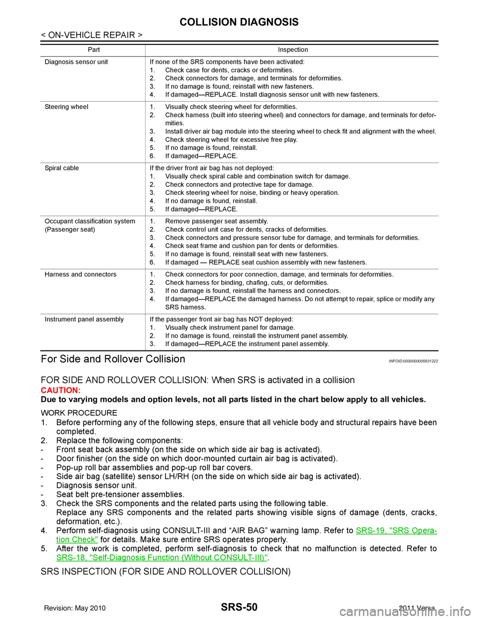
SRS INSPECTION (FOR SIDE AND ROLLOVER COLLISION)
Diagnosis sensor unit If none of the SRS components have been activated:
1. Check case for dents, cracks or deformities.
2. Check connectors for damage, and terminals for deformities.
3. If no damage is found, reinstall with new fasteners.
4. If damaged—REPLACE. Install diagnosis sensor unit with new fasteners.
Steering wheel 1. Visually check steering wheel for deformities.
2. Check harness (built into steering wheel) and connectors for damage, and terminals for defor- mities.
3. Install driver air bag module into the steering wheel to check fit and alignment with the wheel.
4. Check steering wheel for excessive free play.
5. If no damage is found, reinstall.
6. If damaged—REPLACE.
Spiral cable If the driver front air bag has not deployed:
1. Visually check spiral cable and combination switch for damage.
2. Check connectors and protective tape for damage.
3. Check steering wheel for noise, binding or heavy operation.
4. If no damage is found, reinstall.
5. If damaged—REPLACE.
Occupant classification system
(Passenger seat) 1. Remove passenger seat assembly.
2. Check control unit case for dents, cracks of deformities.
3. Check connectors and pressure sensor tube for damage, and terminals for deformities.
4. Check seat frame and cushion pan for dents or deformities.
5. If no damage is found, reinstall seat with new fasteners.
6. If damaged — REPLACE seat cushion assembly with new fasteners.
Harness and connectors 1. Check connectors for poor connection, damage, and terminals for deformities.
2. Check harness for binding, chafing, cuts, or deformities.
3. If no damage is found, reinstall the harness and connectors.
4. If damaged—REPLACE the damaged harness. Do not attempt to repair, splice or modify any
SRS harness.
Instrument panel assembly If the passenger front air bag has NOT deployed: 1. Visually check instrument panel for damage.
2. If no damage is found, reinstall the instrument panel assembly.
3. If damaged—REPLACE the instrument panel assembly.
Part
Inspection
Revision: May 2010 2011 Versa
Page 3685 of 3787
COLLISION DIAGNOSISSRS-51
< ON-VEHICLE REPAIR >
C
DE
F
G
I
J
K L
M A
B
SRS
N
O P
FOR SIDE AND ROLLOVER COLLISION: When SRS is not activated in a collision
CAUTION:
Due to varying models and option levels, not all parts listed in the chart below apply to all vehicles.
WORK PROCEDURE
1. Before performing any of the following steps, ensur e that all vehicle body and structural repairs have been
completed.
2. Check the SRS components and the related parts using the following table.
- If the front seat back assembly is damaged, t he front seat back assembly must be replaced.
- If the door finisher assembly is damaged, the door finisher assembly and door-mounted curtain air bag
module must be replaced.
3. Perform self-diagnosis using CONSULT-III and “AIR BAG” warning lamp. Refer to SRS-19, "
SRS Opera-
tion Check" for details. Make sure entire SRS operates properly.
4. After the work is completed, perform self-diagnosis to check that no malfunction is detected. Refer to
SRS-18, "
Self-Diagnosis Function (Without CONSULT-III)".
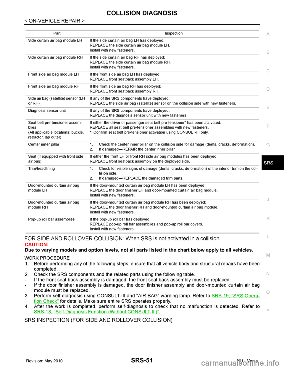
SRS INSPECTION (FOR SIDE AND ROLLOVER COLLISION)
Part Inspection
Side curtain air bag module LH If the side curtain air bag LH has deployed: REPLACE the side curtain air bag module LH.
Install with new fasteners.
Side curtain air bag module RH If the side curtain air bag RH has deployed: REPLACE the side curtain air bag module RH.
Install with new fasteners.
Front side air bag module LH If the front side air bag LH has deployed: REPLACE front seatback assembly LH.
Front side air bag module RH If the front side air bag RH has deployed: REPLACE front seatback assembly RH.
Side air bag (satellite) sensor (LH
or RH) If any of the SRS components have deployed:
REPLACE the side air bag (satellite) sensor on the collision side with new fasteners.
Diagnosis sensor unit If any of the SRS components have deployed:
REPLACE the diagnosis sensor unit with new fasteners.
Seat belt pre-tensioner assem-
blies
(All applicable locations: buckle,
retractor, lap outer) If either the driver or passenger seat belt pre-tensioner* has been activated:
REPLACE all seat belt pre-tensioner assemblies with new fasteners.
*: Confirm seat belt pre-tensioner activation using CONSULT-III only.
Center inner pillar 1. Check the center inner pillar on the collision side for damage (dents, cracks, deformation).
2. If damaged—REPAIR the center inner pillar.
Seat (if equipped with front side
air bag) If either the front LH or front RH side air bag modules has been deployed:
REPLACE front seatback assembly on the deployed side.
Trim/headlining 1. Check for visible signs of damage (dents, cracks, deformation) of the interior trim on the col-
lision side.
2. If damaged—REPLACE the damaged trim parts.
Door-mounted curtain air bag
module LH If the door-mounted curtain air bag module LH has been deployed:
REPLACE the door finisher LH and door-mounted curtain air bag module.
Install with new fasteners.
Door-mounted curtain air bag
module RH If the door-mounted curtain air bag module RH has been deployed:
REPLACE the door finisher RH and door-mounted curtain air bag module.
Install with new fasteners.
Pop-up roll bar assemblies If the pop-up roll bar has deployed: REPLACE pop-up roll bar assemblies and pop-up roll bar covers.
Install with new fasteners.
Revision: May 2010 2011 Versa
Page 3687 of 3787
COLLISION DIAGNOSISSRS-53
< ON-VEHICLE REPAIR >
C
DE
F
G
I
J
K L
M A
B
SRS
N
O P
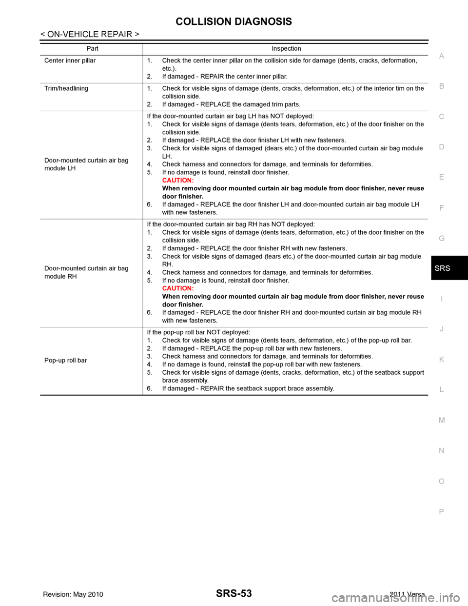
Center inner pillar 1. Check the center inner pillar on the collision side for damage (dents, cracks, deformation,
etc.).
2. If damaged - REPAIR the center inner pillar.
Trim/headlining 1. Check for visible signs of damage (dents, cracks, deformation, etc.) of the interior tim on the
collision side.
2. If damaged - REPLACE the damaged trim parts.
Door-mounted curtain air bag
module LH If the door-mounted curtain air bag LH has NOT deployed:
1. Check for visible signs of damage (dents tears, deformation, etc.) of the door finisher on the
collision side.
2. If damaged - REPLACE the door finisher LH with new fasteners.
3. Check for visible signs of damaged (dears etc.) of the door-mounted curtain air bag module
LH.
4. Check harness and connectors for damage, and terminals for deformities.
5. If no damage is found, reinstall door finisher.
CAUTION:
When removing door mounted curtain air ba g module from door finisher, never reuse
door finisher.
6. If damaged - REPLACE the door finisher LH and door-mounted curtain air bag module LH with new fasteners.
Door-mounted curtain air bag
module RH If the door-mounted curtain air bag RH has NOT deployed:
1. Check for visible signs of damage (dents tears, deformation, etc.) of the door finisher on the
collision side.
2. If damaged - REPLACE the door finisher RH with new fasteners.
3. Check for visible signs of damaged (tears etc.) of the door-mounted curtain air bag module
RH.
4. Check harness and connectors for damage, and terminals for deformities.
5. If no damage is found, reinstall door finisher.
CAUTION:
When removing door mounted curtain air ba g module from door finisher, never reuse
door finisher.
6. If damaged - REPLACE the door finisher RH and door-mounted curtain air bag module RH with new fasteners.
Pop-up roll bar If the pop-up roll bar NOT deployed:
1. Check for visible signs of damage (dents tears, deformation, etc.) of the pop-up roll bar.
2. If damaged - REPLACE the pop-up roll bar with new fasteners.
3. Check harness and connectors for damage, and terminals for deformities.
4. If no damage is found, reinstall the pop-up roll bar with new fasteners.
5. Check for visible signs of damage (dents, cracks, deformation, etc.) of the seatback support
brace assembly.
6. If damaged - REPAIR the seatback support brace assembly.
Part
Inspection
Revision: May 2010 2011 Versa
Page 3771 of 3787
FRONT WIPER AND WASHER SYSTEMWW-25
< SERVICE INFORMATION >
C
DE
F
G H
I
J
L
M A
B
WW
N
O P
Removal and Installation of Front Wiper and Washer SwitchINFOID:0000000005929232
REMOVAL
1. Remove the steering column cover. Refer to IP-11 .
2. Disconnect the wiper and washer switch connector.
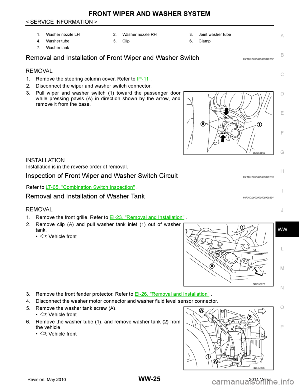
3. Pull wiper and washer switch (1) toward the passenger door while pressing pawls (A) in direction shown by the arrow, and
remove it from the base.
INSTALLATION
Installation is in the reverse order of removal.
Inspection of Front Wiper and Washer Switch CircuitINFOID:0000000005929233
Refer to LT-65, "Combination Switch Inspection" .
Removal and Installation of Washer TankINFOID:0000000005929234
REMOVAL
1. Remove the front grille. Refer to EI-23, "Removal and Installation" .
2. Remove clip (A) and pull washer tank inlet (1) out of washer tank.
• : Vehicle front
3. Remove the front fender protector. Refer to EI-26, "
Removal and Installation" .
4. Disconnect the washer motor connector and washer fluid level sensor connector.
5. Remove the washer tank screw (A). • : Vehicle front
6. Remove the washer tube (1), and remove washer tank (2) from the vehicle.
• : Vehicle front
1. Washer nozzle LH 2. Washer nozzle RH 3. Joint washer tube
4. Washer tube 5. Clip 6. Clamp
7. Washer tank
SKIB5666E
SKIB5667E
SKIB5668E
Revision: May 2010 2011 Versa
Page 3782 of 3787
WW-36
< SERVICE INFORMATION >
REAR WIPER AND WASHER SYSTEM
Removal
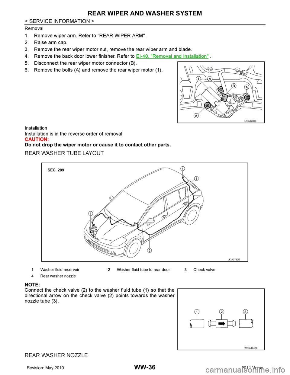
1. Remove wiper arm. Refer to "REAR WIPER ARM" .
2. Raise arm cap.
3. Remove the rear wiper motor nut, remove the rear wiper arm and blade.
4. Remove the back door lower finisher. Refer to EI-40, "
Removal and Installation" .
5. Disconnect the rear wiper motor connector (B).
6. Remove the bolts (A) and remove the rear wiper motor (1).
Installation
Installation is in the reverse order of removal.
CAUTION:
Do not drop the wiper motor or cause it to contact other parts.
REAR WASHER TUBE LAYOUT
NOTE:
Connect the check valve (2) to the washer fluid tube (1) so that the
directional arrow on the check valve (2) points towards the washer
nozzle tube (3).
REAR WASHER NOZZLE
LKIA0789E
1 Washer fluid reservoir 2 Washer fluid tube to rear door 3 Check valve
4 Rear washer nozzle
LKIA0790E
WKIA4242E
Revision: May 2010 2011 Versa
Page 3783 of 3787
REAR WIPER AND WASHER SYSTEMWW-37
< SERVICE INFORMATION >
C
DE
F
G H
I
J
L
M A
B
WW
N
O P
Removal
1. Remove the back door side garnish. Refer to
EI-40, "Removal and Installation" .
2. Disconnect rear washer tube from rear washer nozzle.
3. Release retaining clips and remove washer nozzle.
Installation
Installation is in the reverse order of removal.
NOTE:
• Do not pinch the rear washer tube when installing the back door side garnish.
• Inspect rear washer nozzle for proper spray pattern, adjust as necessary. Refer to WW-37, "
Washer Nozzle
Adjustment".
WASHER FLUID RESERVOIR
Refer to WW-25, "Removal and Installation of Washer Tank" .
WIPER AND WASHER SWITCH
Refer to WW-25, "Removal and Installation of Front Wiper and Washer Switch" .
WASHER MOTOR
Refer to WW-26, "Removal and Installation of Front Washer Motor" .
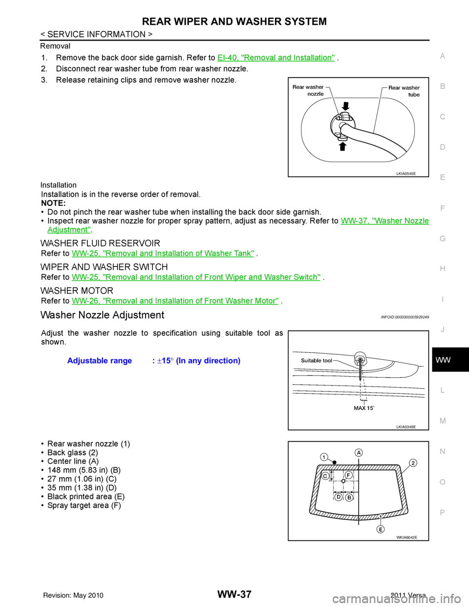
Washer Nozzle AdjustmentINFOID:0000000005929249
Adjust the washer nozzle to specification using suitable tool as
shown.
• Rear washer nozzle (1)
• Back glass (2)
• Center line (A)
• 148 mm (5.83 in) (B)
• 27 mm (1.06 in) (C)
• 35 mm (1.38 in) (D)
• Black printed area (E)
• Spray target area (F)
LKIA0545E
Adjustable range : ±15° (In any direction)
LKIA0349E
WKIA6042E
Revision: May 2010 2011 Versa