Page 236 of 3787
KEY INTERLOCK CABLEAT-219
< SERVICE INFORMATION >
DE
F
G H
I
J
K L
M A
B
AT
N
O P
KEY INTERLOCK CABLE
Removal and InstallationINFOID:0000000005928277
COMPONENTS
REMOVAL
CAUTION:
Make sure that parking brake is applie d before removal and installation.
1. Place the shift selector in the “N” position.
2. Remove the shift selector handle. Refer to AT-216, "
Shift Selector Handle Removal and Installation".
3. Remove the center console assembly. Refer to IP-11
.
4. Slide the slider (A) toward the casing cap (B) while pressing tabs (C) on the slider to separate the slider (A) from the adjust holder
(D).
5. Remove the casing cap (B) from the cable bracket on the A/T shift selector assembly.
6. Remove the key interlock cable from the key interlock rod (E).
1. Key interlock cable 2. Key cylinder3. A/T shift selector assembly
A. Lock plate B. HolderC. Clip
D. Slider E. Key interlock rodF. Adjust holder
G. C a s i n g c a p
WCIA0621E
SCIA6975E
Revision: May 2010 2011 Versa
Page 237 of 3787

AT-220
< SERVICE INFORMATION >
KEY INTERLOCK CABLE
7. Remove steering column cover (upper and lower) and instru-ment lower finisher. Refer to IP-11
.
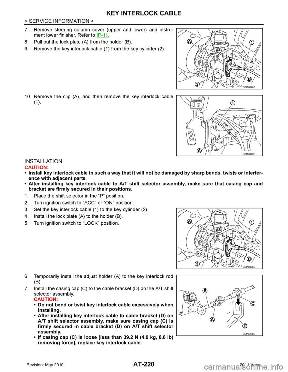
8. Pull out the lock plate (A) from the holder (B).
9. Remove the key interlock cable (1) from the key cylinder (2).
10. Remove the clip (A), and then remove the key interlock cable (1).
INSTALLATION
CAUTION:
• Install key interlock cable in such a way that it will not be damaged by sharp bends, twists or interfer-
ence with adjacent parts.
• After installing key interlock cable to A/T shift selector assembly, make sure that casing cap and bracket are firmly secured in their positions.
1. Place the shift selector in the “P” position.
2. Turn ignition switch to “ACC” or “ON” position.
3. Set the key interlock cable (1) to the key cylinder (2).
4. Install the lock plate (A) to the holder (B).
5. Turn ignition switch to “LOCK” position.
6. Temporarily install the adjust holder (A) to the key interlock rod (B).
7. Install the casing cap (C) to the cable bracket (D) on the A/T shift selector assembly.
CAUTION:
• Do not bend or twist key interlock cable excessively wheninstalling.
• After installing key interlock cable to cable bracket (D) on A/T shift selector assembly, make sure casing cap (C) is
firmly secured in cable bracket (D) on A/T shift selector
assembly.
• If casing cap (C) is loose [less than 39.2 N (4.0 kg, 8.8 lb)
removing force], replace key interlock cable.
SCIA6976E
SCIA6973E
SCIA6976E
SCIA6188E
Revision: May 2010 2011 Versa
Page 238 of 3787
KEY INTERLOCK CABLEAT-221
< SERVICE INFORMATION >
DE
F
G H
I
J
K L
M A
B
AT
N
O P
8. Slide the slider (A) toward the key interlock rod (D) while press- ing the pull lock (B) down to securely connect the adjust holder
(C) with the key interlock rod (D).
CAUTION:
• Do not press tabs when holding slider (A).
• Do not apply any side to side force to key interlock rod (D)when sliding slider (A).
9. Secure the key interlock cable (1) with the clip (A).
10. Install steering column cover (upper and lower) and instrument lower finisher. Refer to IP-11
.
11. Install the center console assembly. Refer to IP-11
.
12. Install the shift selector handle. Refer to AT-216, "
Shift Selector
Handle Removal and Installation".
13. Check shift lock system. Refer to AT-206, "
Description".
SCIA6978E
SCIA6973E
Revision: May 2010 2011 Versa
Page 520 of 3787

BL-10
< SERVICE INFORMATION >
SQUEAK AND RATTLE TROUBLE DIAGNOSES
Most of these incidents can be repaired by adjusting, securing or insulating the item(s) or component(s) caus-
ing the noise.
SUNROOF/HEADLINING
Noises in the sunroof/headlining area c an often be traced to one of the following:
1. Sunroof lid, rail, linkage or seals making a rattle or light knocking noise
2. Sun visor shaft shaking in the holder
3. Front or rear windshield touching headliner and squeaking
Again, pressing on the components to stop the noise while duplicating the conditions can isolate most of these
incidents. Repairs usually consist of insulating with felt cloth tape.
OVERHEAD CONSOLE (FRONT AND REAR)
Overhead console noises are often caused by the c onsole panel clips not being engaged correctly. Most of
these incidents are repaired by pushing up on the c onsole at the clip locations until the clips engage.
In addition look for:
1. Loose harness or harness connectors.
2. Front console map/reading lamp lense loose.
3. Loose screws at console attachment points.
SEATS
When isolating seat noise it's important to note the pos ition the seat is in and the load placed on the seat when
the noise is present. These conditions should be duplicated when verifying and isolating the cause of the
noise.
Cause of seat noise include:
1. Headrest rods and holder
2. A squeak between the seat pad cushion and frame
3. The rear seatback lock and bracket
These noises can be isolated by moving or pressing on the suspected components while duplicating the con-
ditions under which the noise occurs. Most of thes e incidents can be repaired by repositioning the component
or applying urethane tape to the contact area.
UNDERHOOD
Some interior noise may be caused by components under the hood or on the engine wall. The noise is then
transmitted into the passenger compartment.
Causes of transmitted underhood noise include:
1. Any component mounted to the engine wall
2. Components that pass through the engine wall
3. Engine wall mounts and connectors
4. Loose radiator mounting pins
5. Hood bumpers out of adjustment
6. Hood striker out of adjustment
These noises can be difficult to isolate since they cannot be reached from the interior of the vehicle. The best
method is to secure, move or insulate one component at a time and test drive the \
vehicle. Also, engine RPM
or load can be changed to isolate the noise. Repairs can usually be made by moving, adjusting, securing, or
insulating the component causing the noise.
Revision: May 2010 2011 Versa
Page 524 of 3787
BL-14
< SERVICE INFORMATION >
HOOD
5. After adjustment tighten lock bolts to the specified torque.
6. Install the front grille. Refer to EI-23
.
Removal and InstallationINFOID:0000000005929277
HOOD ASSEMBLY
Removal
1. Remove hinge nuts on hood and remove hood assembly.
CAUTION:
Two technicians should be used to avoid damaging the
hood during removal.
1. Hood striker 2. Primary latch 3. Secondary striker
4. Secondary latch
A : 20 mm (0.79 in)
B : 6.8 mm (0.268 in) min.
PIIB5794E
1. Hood hinge 2. Hood stay3. Radiator core seal rubber
4. Hood assembly 5. Hood insulator 6. Hood stay holder
PIIB2528J
12.7 N·m (1.3 kg-m, 9.4 ft-lb)
PIIB2529J
Revision: May 2010 2011 Versa
Page 677 of 3787

FRONT DOOR LOCKBL-167
< SERVICE INFORMATION >
C
DE
F
G H
J
K L
M A
B
BL
N
O P
FRONT DOOR LOCK
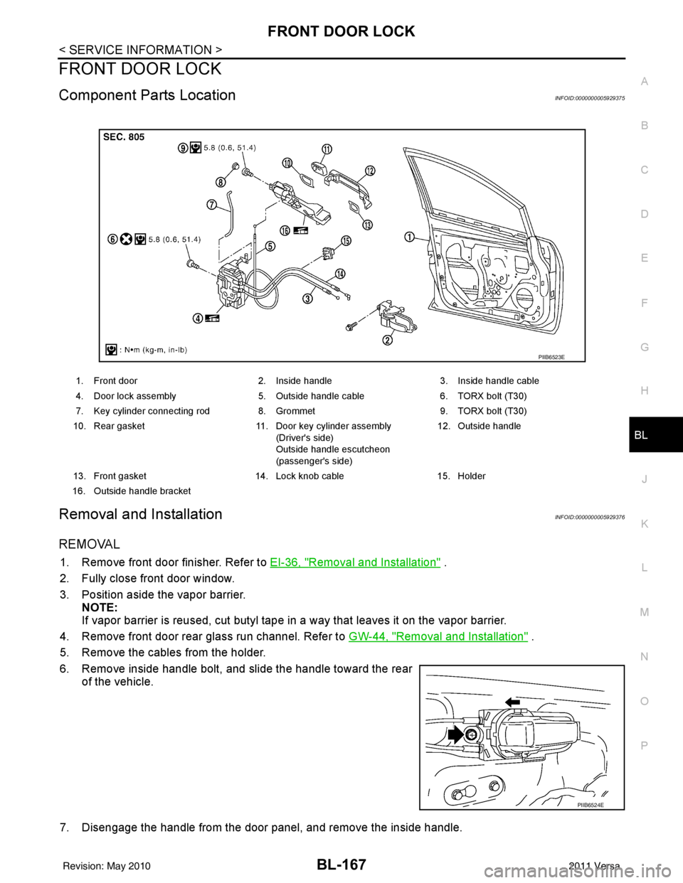
Component Parts LocationINFOID:0000000005929375
Removal and InstallationINFOID:0000000005929376
REMOVAL
1. Remove front door finisher. Refer to EI-36, "Removal and Installation" .
2. Fully close front door window.
3. Position aside the vapor barrier. NOTE:
If vapor barrier is reused, cut butyl tape in a way that leaves it on the vapor barrier.
4. Remove front door rear glass run channel. Refer to GW-44, "
Removal and Installation" .
5. Remove the cables from the holder.
6. Remove inside handle bolt, and slide the handle toward the rear of the vehicle.
7. Disengage the handle from the door panel, and remove the inside handle.
1. Front door 2. Inside handle3. Inside handle cable
4. Door lock assembly 5. Outside handle cable6. TORX bolt (T30)
7. Key cylinder connecting rod 8. Grommet9. TORX bolt (T30)
10. Rear gasket 11. Door key cylinder assembly
(Driver's side)
Outside handle escutcheon
(passenger's side) 12. Outside handle
13. Front gasket 14. Lock knob cable15. Holder
16. Outside handle bracket
PIIB6523E
PIIB6524E
Revision: May 2010 2011 Versa
Page 679 of 3787
FRONT DOOR LOCKBL-169
< SERVICE INFORMATION >
C
DE
F
G H
J
K L
M A
B
BL
N
O P
15. Remove the door lock assembly bolts.
16. Slide the outside handle bracket toward the rear of the vehicle, and remove the assembly.
17. If equipped, disconnect the door lock assembly electrical connector.
18. Separate the outside handle cable from the outside handle bracket.
INSTALLATION
Installation is in the reverse order of removal.
CAUTION:
• To install each rod, be sure to rotate the rod holder until a click is felt.
• When installing door lock assembly, be careful when rotating the outside handle cable as shown in
the figure.
- Place the outside handle bracket cable on the inside of door
lock assembly before installing. 5.8 N·m (0.6 kg-m, 51.4 in-lb)
PIIB6527E
PIIB6528E
PIIB5815E
PIIB6529E
Revision: May 2010
2011 Versa
Page 682 of 3787
BL-172
< SERVICE INFORMATION >
REAR DOOR LOCK
10. Slide the outside handle bracket toward the rear of vehicle,remove the outside handle bracket and the door lock assembly.
11. If equipped, disconnect the door lock assembly electrical connector.
12. Disconnect the outside handle cable from the outside handle bracket.
INSTALLATION
Installation is in the reverse order of removal.
CAUTION:
• To install each rod, be sure to rotate the rod holder until a click is felt.
• When installing door lock assembly, be careful wh en rotating the outside handle cable as shown.
- Place the outside handle bracket cable on the inside of door
lock assembly before installing.
PIIB6528E
PIIB5815E
PIIB6529E
Revision: May 2010 2011 Versa