2011 NISSAN TIIDA fuse and relay location
[x] Cancel search: fuse and relay locationPage 418 of 3787
![NISSAN TIIDA 2011 Service Repair Manual AUDIOAV-21
< SERVICE INFORMATION > [AUDIO WITHOUT NAVIGATION]
C
D
E
F
G H
I
J
L
M A
B
AV
N
O P
NOTE:
Noise resulting from variations in field strength, such as fading noise and multi-path noise, or e NISSAN TIIDA 2011 Service Repair Manual AUDIOAV-21
< SERVICE INFORMATION > [AUDIO WITHOUT NAVIGATION]
C
D
E
F
G H
I
J
L
M A
B
AV
N
O P
NOTE:
Noise resulting from variations in field strength, such as fading noise and multi-path noise, or e](/manual-img/5/57396/w960_57396-417.png)
AUDIOAV-21
< SERVICE INFORMATION > [AUDIO WITHOUT NAVIGATION]
C
D
E
F
G H
I
J
L
M A
B
AV
N
O P
NOTE:
Noise resulting from variations in field strength, such as fading noise and multi-path noise, or external noise
from trains and other sources. It is not a malfunction.
• Fading noise: This noise occurs because of variations in the field strength in a narrow range due to moun-
tains or buildings blocking the signal.
• Multi-path noise: This noise results from the waves sent directly from the broadcast station arriving at the antenna at a different time from the waves t hat reflect off of mountains or buildings.
Noise InspectionINFOID:0000000005931285
The vehicle itself can be a source of noise if noise prevention parts or electrical equipment is malfunctioning.
Check if noise is caused and/or changed by engine speed, ignition switch turned to each position, and opera-
tion of each piece of electrical equipment, and determine the cause.
NOTE:
The source of the noise can be found easily by listening to the noise while removing the fuses of electrical
components, one by one.
TYPE OF NOISE AND POSSIBLE CAUSE
No sound can be heard from one or several speakers. • Open or short in audio signal circuit between audio unit and front
speaker. Refer to AV- 2 4 , "
Sound Is Not Heard from Front Door
Speaker (Base System)" or AV- 2 6 , "Sound Is Not Heard from
Front Door Speaker or Tweeter (Premium System)" .
• Front speaker. Refer to AV- 2 4 , "
Sound Is Not Heard from Front
Door Speaker (Base System)" or AV- 2 6 , "Sound Is Not Heard
from Front Door Speaker or Tweeter (Premium System)" .
• Open or short in audio signal circuit between audio unit and rear
speaker. Refer to AV- 2 5 , "
Sound Is Not Heard from Rear Door
Speaker (Base System)" or AV- 2 7 , "Sound Is Not Heard from
Rear Door Speaker (Premium System)" .
• Rear speaker. Refer to AV- 2 5 , "
Sound Is Not Heard from Rear
Door Speaker (Base System)" or AV- 2 7 , "Sound Is Not Heard
from Rear Door Speaker (Premium System)" .
• Tweeter (mid level and premium system) AV- 2 6 , "
Sound Is Not
Heard from Front Door Speaker or Tweeter (Premium System)"
or AV- 2 7 , "
Sound Is Not Heard from Rear Door Speaker (Premi-
um System)" .
• Audio unit. Refer to AV- 2 9 , "
Removal and Installation" .
No sound can be heard from radio or noise is heard. • Antenna feeder. Refer to
AV- 3 3 , "
Location of Antenna" .
• Antenna. Refer to AV- 3 3 , "
Location of Antenna" .
• Audio unit. Refer to AV- 2 9 , "
Removal and Installation" .
Symptom
Check item
Occurrence condition Possible cause
Occurs only when engine is ON. A continuous growling noise occurs. The speed of
the noise varies with changes in the engine speed.
Ignition components
A whistling noise occurs while the engine speed is
high. A booming noise occurs while the engine is
running and the lighting switch is ON. Generator
Noise only occurs when various
electrical components are oper-
ating. A cracking or snapping sound occurs with the op-
eration of various switches.
Relay malfunction, radio malfunction
The noise occurs when various motors are operat-
ing. • Motor case ground
•Motor
The noise occurs constantly, not just under certain conditions. • Rear defogger coil malfunction
• Open circuit in printed heater
A cracking or snapping sound occurs while the vehicle is being driven, especially when
it is vibrating excessively. • Ground wire of body parts.
• Ground due to improper part installation
• Wiring connections or a short circuit
Revision: May 2010
2011 Versa
Page 463 of 3787
![NISSAN TIIDA 2011 Service Repair Manual AV-66
< SERVICE INFORMATION >[AUDIO WITH NAVIGATION]
AUDIO
END ON-BOARD DIAGNOSIS
Turn OFF ignition switch.
Noise InspectionINFOID:0000000005931317
The vehicle itself can be a source of noise if noise NISSAN TIIDA 2011 Service Repair Manual AV-66
< SERVICE INFORMATION >[AUDIO WITH NAVIGATION]
AUDIO
END ON-BOARD DIAGNOSIS
Turn OFF ignition switch.
Noise InspectionINFOID:0000000005931317
The vehicle itself can be a source of noise if noise](/manual-img/5/57396/w960_57396-462.png)
AV-66
< SERVICE INFORMATION >[AUDIO WITH NAVIGATION]
AUDIO
END ON-BOARD DIAGNOSIS
Turn OFF ignition switch.
Noise InspectionINFOID:0000000005931317
The vehicle itself can be a source of noise if noise
prevention parts or electrical equipment is malfunctioning.
Check if noise is caused and/or changed by engine speed, ignition switch turned to each position, and opera-
tion of each piece of electrical equipment, and determine the cause.
NOTE:
The source of the noise can be found easily by listening to the noise while removing the fuses of electrical
components, one by one.
TYPE OF NOISE AND POSSIBLE CAUSE
Symptom ChartINFOID:0000000006216708
MALFUNCTION WITH NAVIGATION
System configuration • 8 pulses speed
• Clock ON/OFF
• Equalizer setup X11C
• RF tuning
• Antenna type
• Sound system
• Sub Out: Code
• Steering wheel The device is configured by a connect-
ed hardware circuit.
The parameter is
influenced.
Self test •Bluetooth
® module Access Mal-
function
• SD-card Access Malfunction
• Radio-Antenna Circuit Malfunc-
tion
• GPS Antenna Circuit Malfunc-
tion
• Microphone Circuit Malfunction A system self test is executed: the re-
sult is stored into
the error memory
which is shown afterwards as a list of
codes of the detected malfunctions.
Mode
ItemContent
Occurrence condition Possible cause
Occurs only when engine is ON. A continuous growling noise occurs. The speed of
the noise varies with changes in the engine speed.
Ignition components
A whistling noise occurs while the engine speed is
high. A booming noise occurs while the engine is
running and the lighting switch is ON. Generator
Noise only occurs when various
electrical components are oper-
ating. A cracking or snapping sound occurs with the op-
eration of various switches.
Relay malfunction, radio malfunction
The noise occurs when various motors are operat-
ing. • Motor case ground
• Motor
The noise occurs constantly, not just under certain conditions. • Rear defogger coil malfunction
• Open circuit in printed heater
A cracking or snapping sound occurs while the vehicle is being driven, especially when
it is vibrating excessively. • Ground wire of body parts.
• Ground due to improper part installation
• Wiring connections or a short circuit
Symptoms
Check itemsProbable malfunction location / Action to
take
Display does not turn ON. All switches cannot be operated.
AV control unit power supply and ground
circuit. Refer to
AV- 6 9
.
All switches can be operated. AV control unit. Refer to AV- 6 9
.
Revision: May 2010 2011 Versa
Page 568 of 3787
BL-58
< SERVICE INFORMATION >
REMOTE KEYLESS ENTRY SYSTEM
REMOTE KEYLESS ENTRY SYSTEM
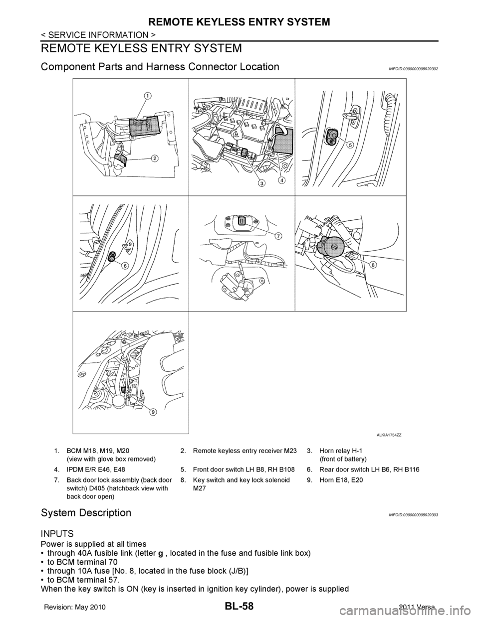
Component Parts and Harness Connector LocationINFOID:0000000005929302
System DescriptionINFOID:0000000005929303
INPUTS
Power is supplied at all times
• through 40A fusible link (letter g , located in the fuse and fusible link box)
• to BCM terminal 70
• through 10A fuse [No. 8, located in the fuse block (J/B)]
• to BCM terminal 57.
When the key switch is ON (key is inserted in ignition key cylinder), power is supplied
ALKIA1754ZZ
1. BCM M18, M19, M20
(view with glove box removed) 2. Remote keyless entry receiver M23 3. Horn relay H-1
(front of battery)
4. IPDM E/R E46, E48 5. Front door switch LH B8, RH B108 6. Rear door switch LH B6, RH B116
7. Back door lock assembly (back door switch) D405 (hatchback view with
back door open) 8. Key switch and key lock solenoid
M27 9. Horn E18, E20
Revision: May 2010
2011 Versa
Page 2720 of 3787
GI-16
< SERVICE INFORMATION >
HOW TO USE THIS MANUAL
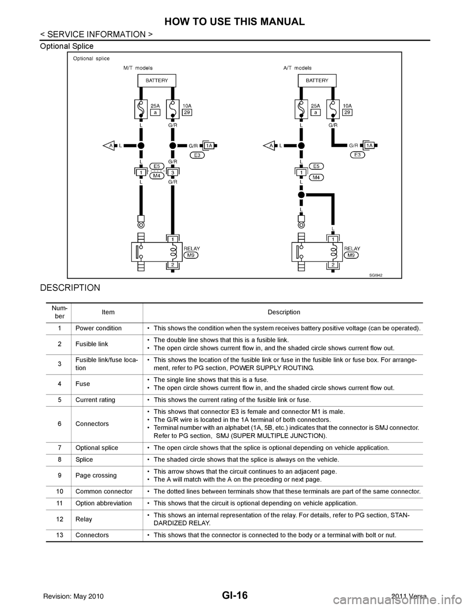
Optional Splice
DESCRIPTION
SGI942
Num-ber Item
Description
1 Power condition • This shows the condition when the system receives battery positive voltage (can be operated).
2 Fusible link • The double line shows that this is a fusible link.
• The open circle shows current flow in, and the shaded circle shows current flow out.
3 Fusible link/fuse loca-
tion • This shows the location of the fusible link or fuse in the fusible link or fuse box. For arrange-
ment, refer to PG section, POWER SUPPLY ROUTING.
4Fuse • The single line shows that this is a fuse.
• The open circle shows current flow in, and the shaded circle shows current flow out.
5 Current rating • This shows the current rating of the fusible link or fuse.
6 Connectors • This shows that connector E3 is female and connector M1 is male.
• The G/R wire is located in the 1A terminal of both connectors.
• Terminal number with an alphabet (1A, 5B, etc.) indicates that the connector is SMJ connector.
Refer to PG section, SMJ (SUPER MULTIPLE JUNCTION).
7 Optional splice • The open circle shows that the splice is optional depending on vehicle application.
8 Splice • The shaded circle shows that the splice is always on the vehicle.
9 Page crossing • This arrow shows that the circuit continues to an adjacent page.
• The A will match with the A on the preceding or next page.
10 Common connector • The dotted lines between terminals show that these terminals are part of the same connector. 11 Option abbreviation • This shows that the circuit is optional depending on vehicle application.
12 Relay • This shows an internal representation of the relay. For details, refer to PG section, STAN-
DARDIZED RELAY.
13 Connectors • This shows that the connector is connected to the body or a terminal with bolt or nut.
Revision: May 2010 2011 Versa
Page 3037 of 3787
HEADLAMP (FOR USA)LT-5
< SERVICE INFORMATION >
C
DE
F
G H
I
J
L
M A
B
LT
N
O P
HEADLAMP (FOR USA)
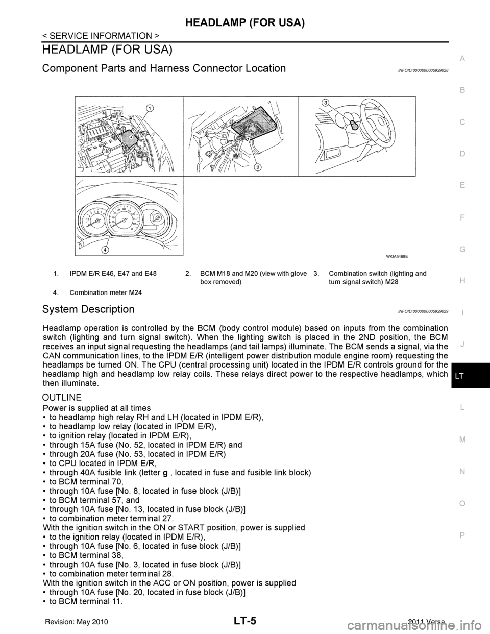
Component Parts and Har ness Connector LocationINFOID:0000000005929028
System DescriptionINFOID:0000000005929029
Headlamp operation is controlled by the BCM (body c ontrol module) based on inputs from the combination
switch (lighting and turn signal switch). When the light ing switch is placed in the 2ND position, the BCM
receives an input signal requesting the headlamps (and tail lamps) illuminate. The BCM sends a signal, via the
CAN communication lines, to the IPDM E/R (intelligent power distribution module engine room) requesting the
headlamps be turned ON. The CPU (centra l processing unit) located in the IPDM E/R controls ground for the
headlamp high and headlamp low relay coils. These relays direct power to the respective headlamps, which
then illuminate.
OUTLINE
Power is supplied at all times
• to headlamp high relay RH and LH (located in IPDM E/R),
• to headlamp low relay (located in IPDM E/R),
• to ignition relay (located in IPDM E/R),
• through 15A fuse (No. 52, located in IPDM E/R) and
• through 20A fuse (No. 53, located in IPDM E/R)
• to CPU located in IPDM E/R,
• through 40A fusible link (letter g , located in fuse and fusible link block)
• to BCM terminal 70,
• through 10A fuse [No. 8, located in fuse block (J/B)]
• to BCM terminal 57, and
• through 10A fuse [No. 13, located in fuse block (J/B)]
• to combination meter terminal 27.
With the ignition switch in the ON or START position, power is supplied
• to the ignition relay (located in IPDM E/R),
• through 10A fuse [No. 6, located in fuse block (J/B)]
• to BCM terminal 38,
• through 10A fuse [No. 3, located in fuse block (J/B)]
• to combination meter terminal 28.
With the ignition switch in the ACC or ON position, power is supplied
• through 10A fuse [No. 20, located in fuse block (J/B)]
• to BCM terminal 11.
1. IPDM E/R E46, E47 and E48 2. BCM M18 and M20 (view with glove
box removed)3. Combination switch (lighting and
turn signal switch) M28
4. Combination meter M24
WKIA5469E
Revision: May 2010 2011 Versa
Page 3059 of 3787
HEADLAMP (FOR CANADA) - DAYTIME LIGHT SYSTEM -
LT-27
< SERVICE INFORMATION >
C
D E
F
G H
I
J
L
M A
B
LT
N
O P
HEADLAMP (FOR CANADA) - DAYTIME LIGHT SYSTEM -
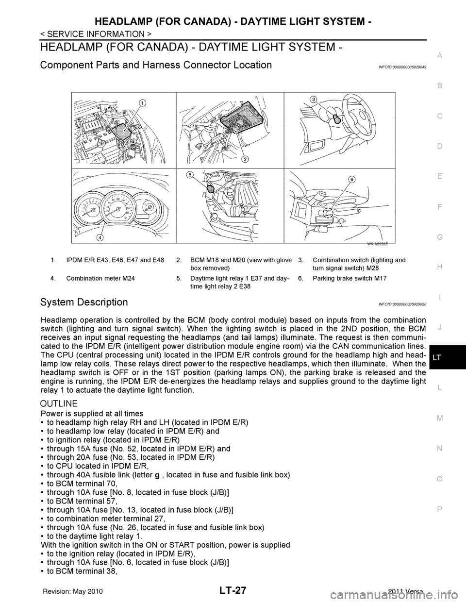
Component Parts and Harness Connector LocationINFOID:0000000005929049
System DescriptionINFOID:0000000005929050
Headlamp operation is controlled by the BCM (body c ontrol module) based on inputs from the combination
switch (lighting and turn signal switch). When the light ing switch is placed in the 2ND position, the BCM
receives an input signal requesting the headlamps (and ta il lamps) illuminate. The request is then communi-
cated to the IPDM E/R (intelligent power distribution module engine room) via the CAN communication lines.
The CPU (central processing unit) located in t he IPDM E/R controls ground for the headlamp high and head-
lamp low relay coils. These relays direct power to the respective headlamps, which then illuminate. When the
headlamp switch is OFF or in the 1ST position (parking lamps ON), the parking brake is released and the
engine is running, the IPDM E/R de-energizes the headlamp relays and supplies ground to the daytime light
relay 1 to actuate the daytime light function.
OUTLINE
Power is supplied at all times
• to headlamp high relay RH and LH (located in IPDM E/R)
• to headlamp low relay (located in IPDM E/R) and
• to ignition relay (located in IPDM E/R)
• through 15A fuse (No. 52, located in IPDM E/R) and
• through 20A fuse (No. 53, located in IPDM E/R)
• to CPU located in IPDM E/R,
• through 40A fusible link (letter g , located in fuse and fusible link box)
• to BCM terminal 70,
• through 10A fuse [No. 8, located in fuse block (J/B)]
• to BCM terminal 57,
• through 10A fuse [No. 13, located in fuse block (J/B)]
• to combination meter terminal 27,
• through 10A fuse (No. 26, located in fuse and fusible link box)
• to the daytime light relay 1.
With the ignition switch in the ON or START position, power is supplied
• to the ignition relay (located in IPDM E/R),
• through 10A fuse [No. 6, located in fuse block (J/B)]
• to BCM terminal 38,
1. IPDM E/R E43, E46, E47 and E48 2. BCM M18 and M20 (view with glove
box removed)3. Combination switch (lighting and
turn signal switch) M28
4. Combination meter M24 5. Daytime light relay 1 E37 and day-
time light relay 2 E38 6. Parking brake switch M17
WKIA5555E
Revision: May 2010
2011 Versa
Page 3073 of 3787
FRONT FOG LAMPLT-41
< SERVICE INFORMATION >
C
DE
F
G H
I
J
L
M A
B
LT
N
O P
FRONT FOG LAMP
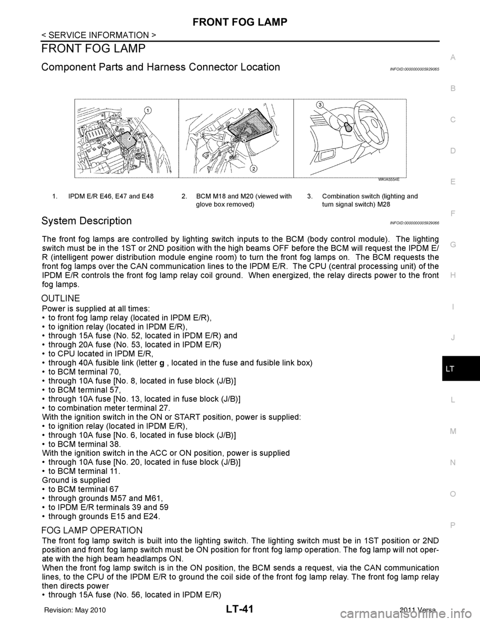
Component Parts and Har ness Connector LocationINFOID:0000000005929065
System DescriptionINFOID:0000000005929066
The front fog lamps are controlled by lighting switch inputs to the BCM (body control module). The lighting
switch must be in the 1ST or 2ND position with the high beams OFF before the BCM will request the IPDM E/
R (intelligent power distribution module engine room) to turn the front fog lamps on. The BCM requests the
front fog lamps over the CAN communication lines to the IPDM E/R. The CPU (central processing unit) of the
IPDM E/R controls the front fog lamp relay coil ground. When energized, the relay directs power to the front
fog lamps.
OUTLINE
Power is supplied at all times:
• to front fog lamp relay (located in IPDM E/R),
• to ignition relay (located in IPDM E/R),
• through 15A fuse (No. 52, located in IPDM E/R) and
• through 20A fuse (No. 53, located in IPDM E/R)
• to CPU located in IPDM E/R,
• through 40A fusible link (letter g , located in the fuse and fusible link box)
• to BCM terminal 70,
• through 10A fuse [No. 8, located in fuse block (J/B)]
• to BCM terminal 57,
• through 10A fuse [No. 13, located in fuse block (J/B)]
• to combination meter terminal 27.
With the ignition switch in the ON or START position, power is supplied:
• to ignition relay (located in IPDM E/R),
• through 10A fuse [No. 6, located in fuse block (J/B)]
• to BCM terminal 38.
With the ignition switch in the ACC or ON position, power is supplied
• through 10A fuse [No. 20, located in fuse block (J/B)]
• to BCM terminal 11.
Ground is supplied
• to BCM terminal 67
• through grounds M57 and M61,
• to IPDM E/R terminals 39 and 59
• through grounds E15 and E24.
FOG LAMP OPERATION
The front fog lamp switch is built into the lighting switch. The lighting switch must be in 1ST position or 2ND
position and front fog lamp switch must be ON position for front fog lamp operation. The fog lamp will not oper-
ate with the high beam headlamps ON.
When the front fog lamp switch is in the ON positi on, the BCM sends a request, via the CAN communication
lines, to the CPU of the IPDM E/R to ground the coil side of the front fog lamp relay. The front fog lamp relay
then directs power
• through 15A fuse (No. 56, located in IPDM E/R)
1. IPDM E/R E46, E47 and E48 2. BCM M18 and M20 (viewed with
glove box removed)3. Combination switch (lighting and
turn signal switch) M28
WKIA5554E
Revision: May 2010 2011 Versa
Page 3106 of 3787
LT-74
< SERVICE INFORMATION >
PARKING, LICENSE PLATE AND TAIL LAMPS
PARKING, LICENSE PLATE AND TAIL LAMPS
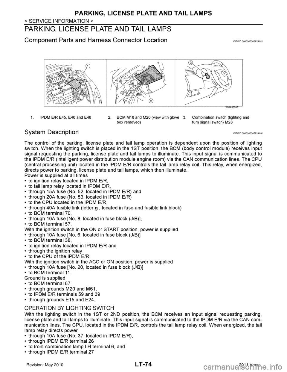
Component Parts and Harness Connector LocationINFOID:0000000005929115
System DescriptionINFOID:0000000005929116
The control of the parking, license plate and tail lamp operation is dependent upon the position of lighting
switch. When the lighting switch is placed in the 1ST position, the BCM (body cont rol module) receives input
signal requesting the parking, license plate and tail lamps to illuminate. This input signal is communicated to
the IPDM E/R (intelligent power distribution module engine room) via the CAN communication lines. The CPU
(central processing unit) located in the IPDM E/R contro ls the tail lamp relay coil. This relay, when energized,
directs power to parking, license plate and tail lamps, which then illuminate.
Power is supplied at all times
• to ignition relay located in IPDM E/R,
• to tail lamp relay located in IPDM E/R,
• through 15A fuse (No. 52, located in IPDM E/R) and
• through 20A fuse (No. 53, located in IPDM E/R)
• to the CPU located in the IPDM E/R,
• through 40A fusible link (letter g , located in fuse and fusible link block)
• to BCM terminal 70,
• through 10A fuse [No. 8, located in fuse block (J/B)],
• to BCM terminal 57.
With the ignition switch in the ON or START position, power is supplied
• through 10A fuse [No. 6, located in fuse block (J/B)]
• to BCM terminal 38,
• to ignition relay located in IPDM E/R and
• through the ignition relay
• to the CPU of the IPDM E/R.
With the ignition switch in the ACC or ON position, power is supplied
• through 10A fuse [No. 20, located in fuse block (J/B)]
• to BCM terminal 11.
Ground is supplied
• to BCM terminal 67
• through grounds M20 and M61,
• to IPDM E/R terminals 59 and 39
• through grounds E15 and E24.
OPERATION BY LIGHTING SWITCH
With the lighting switch in the 1ST or 2ND position, the BCM receives an input signal requesting parking,
license plate and tail lamps to illuminate. This input signal is communicated to the IPDM E/R via the CAN com-
munication lines. The CPU, located in the IPDM E/R, controls the tail lamp relay coil. When energized, the tail
lamp relay directs power
• through 10A fuse (No. 37, located in IPDM E/R),
• through IPDM E/R terminal 26
• to front combination lamp LH terminal 6, and
• through IPDM E/R terminal 27
1. IPDM E/R E45, E46 and E48 2. BCM M18 and M20 (view with glove
box removed)3. Combination switch (lighting and
turn signal switch) M28
WKIA5554E
Revision: May 2010 2011 Versa