2011 NISSAN TIIDA Changing transmission fluid
[x] Cancel search: Changing transmission fluidPage 18 of 3787

AT-1
TRANSMISSION/TRANSAXLE
DE
F
G H
I
J
K L
M
SECTION AT
A
B
AT
N
O P
CONTENTS
AUTOMATIC TRANSAXLE
SERVICE INFORMATION .. ..........................5
INDEX FOR DTC ............................................ .....5
Alphabetical Index ............................................... ......5
DTC No. Index ..........................................................5
PRECAUTIONS ...................................................7
Precaution for Supplemental Restraint System
(SRS) "AIR BAG" and "SEAT BELT PRE-TEN-
SIONER" ............................................................. ......
7
Precaution Necessary for Steering Wheel Rota-
tion After Battery Disconnect ............................... ......
7
Precaution for On Board Diagnosis (OBD) System
of A/T and Engine .....................................................
8
Precaution .................................................................8
Service Notice or Precaution .....................................9
PREPARATION ..................................................11
Special Service Tool ........................................... ....11
Commercial Service Tool ........................................14
A/T FLUID ...........................................................17
Checking A/T Fluid ..................................................17
Changing A/T Fluid .................................................17
A/T Fluid Cooler Cleaning .......................................18
A/T CONTROL SYSTEM ....................................21
Cross-Sectional View ..............................................21
Shift Mechanism .................................................. ....22
TCM Function ..........................................................30
CAN Communication ...............................................31
Input/Output Signal of TCM .....................................31
Line Pressure Control .............................................32
Shift Control ........................................................ ....33
Lock-up Control .......................................................34
Engine Brake Control (Overrun Clutch Control) ......35
Control Valve ....................................................... ....37
Centrifugal Cancel Mechanism ...............................37
ON BOARD DIAGNOSTIC (OBD) SYSTEM ......39
Introduction ......................................................... ....39
OBD-II Function for A/T System ..............................39
One or Two Trip Detection Logic of OBD-II ......... ....39
OBD-II Diagnostic Trouble Code (DTC) ..................39
Malfunction Indicator Lamp (MIL) ............................41
TROUBLE DIAGNOSIS ....................................42
DTC Inspection Priority Chart ..................................42
Fail-Safe ..................................................................42
How to Perform Trouble Diagnosis for Quick and
Accurate Repair .......................................................
43
A/T Electrical Parts Location ...................................49
Circuit Diagram ........................................................50
Inspections Before Trouble Diagnosis .....................51
Road Test ................................................................55
Check Before Engine Is Started ..............................56
Check at Idle ............................................................56
Cruise Test - Part 1 .................................................58
Cruise Test - Part 2 .................................................61
Cruise Test - Part 3 .................................................62
Vehicle Speed at Which Gear Shifting Occurs ........64
Vehicle Speed at Which Lock-up Occurs/Releas-
es .............................................................................
64
Symptom Chart ........................................................65
TCM Terminal and Reference Value .......................75
CONSULT-III Function (TRANSMISSION) .......... ....77
Diagnosis Procedure without CONSULT-III ............82
U1000 CAN COMM CIRCUIT ...........................87
Description ........................................................... ....87
On Board Diagnosis Logic .......................................87
Possible Cause ........................................................87
DTC Confirmation Procedure ..................................87
Wiring Diagram - AT - CAN .....................................88
Diagnosis Procedure ...............................................89
P0705 TRANSMISSION RANGE SWITCH A ...90
Description ...............................................................90
CONSULT-III Reference Value in Data Monitor
Mode .................................................................... ....
90
On Board Diagnosis Logic .......................................90
Possible Cause ........................................................90
DTC Confirmation Procedure ..................................90
Revision: May 2010 2011 Versa
Page 26 of 3787

PRECAUTIONSAT-9
< SERVICE INFORMATION >
DE
F
G H
I
J
K L
M A
B
AT
N
O P
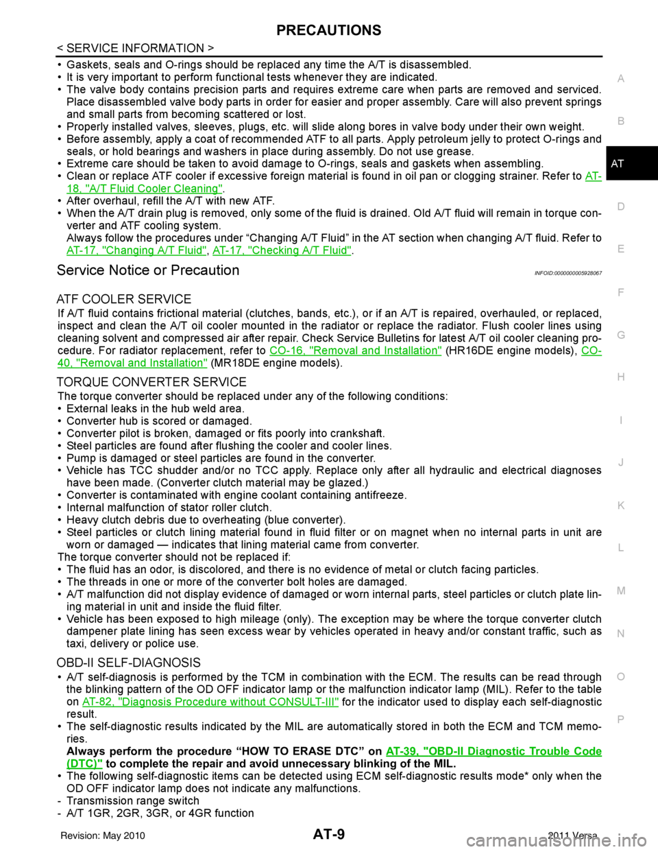
• Gaskets, seals and O-rings should be replaced any time the A/T is disassembled.
• It is very important to perform func tional tests whenever they are indicated.
• The valve body contains precision parts and requires extreme care when parts are removed and serviced.
Place disassembled valve body parts in order for easier and proper assembly. Care will also prevent springs
and small parts from becoming scattered or lost.
• Properly installed valves, sleeves, plugs, etc. will slide along bores in valve body under their own weight.
• Before assembly, apply a coat of recommended ATF to all parts. Apply petroleum jelly to protect O-rings and seals, or hold bearings and washers in pl ace during assembly. Do not use grease.
• Extreme care should be taken to avoid damage to O-rings, seals and gaskets when assembling.
• Clean or replace ATF cooler if excessive foreign material is found in oil pan or clogging strainer. Refer to AT-
18, "A/T Fluid Cooler Cleaning".
• After overhaul, refill the A/T with new ATF.
• When the A/T drain plug is removed, only some of the fluid is drained. Old A/T fluid will remain in torque con- verter and ATF cooling system.
Always follow the procedures under “Changing A/T Fluid” in the AT section when changing A/T fluid. Refer to
AT-17, "
Changing A/T Fluid", AT-17, "Checking A/T Fluid".
Service Notice or PrecautionINFOID:0000000005928067
ATF COOLER SERVICE
If A/T fluid contains frictional material (clutches, bands, etc.), or if an A/T is repaired, overhauled, or replaced,
inspect and clean the A/T oil cooler mounted in the radiator or replace the radiator. Flush cooler lines using
cleaning solvent and compressed air after repair. Check Service Bulletins for latest A/T oil cooler cleaning pro-
cedure. For radiator replacement, refer to CO-16, "
Removal and Installation" (HR16DE engine models), CO-
40, "Removal and Installation" (MR18DE engine models).
TORQUE CONVERTER SERVICE
The torque converter should be replaced under any of the following conditions:
• External leaks in the hub weld area.
• Converter hub is scored or damaged.
• Converter pilot is broken, damaged or fits poorly into crankshaft.
• Steel particles are found after flushing the cooler and cooler lines.
• Pump is damaged or steel particles are found in the converter.
• Vehicle has TCC shudder and/or no TCC apply. Replace only after all hydraulic and electrical diagnoses
have been made. (Converter clutch material may be glazed.)
• Converter is contaminated with engi ne coolant containing antifreeze.
• Internal malfunction of stator roller clutch.
• Heavy clutch debris due to overheating (blue converter).
• Steel particles or clutch lining material found in flui d filter or on magnet when no internal parts in unit are
worn or damaged — indicates that lining material came from converter.
The torque converter should not be replaced if:
• The fluid has an odor, is discolored, and there is no evidence of metal or clutch facing particles.
• The threads in one or more of the converter bolt holes are damaged.
• A/T malfunction did not display evidence of damaged or worn internal parts, steel particles or clutch plate lin-
ing material in unit and inside the fluid filter.
• Vehicle has been exposed to high mileage (only). The e xception may be where the torque converter clutch
dampener plate lining has seen excess wear by vehicles operated in heavy and/or constant traffic, such as
taxi, delivery or police use.
OBD-II SELF-DIAGNOSIS
• A/T self-diagnosis is performed by the TCM in combination with the ECM. The results can be read through the blinking pattern of the OD OFF indicator lamp or the malfunction indicator lamp (MIL). Refer to the table
on AT-82, "
Diagnosis Procedure without CONSULT-III" for the indicator used to display each self-diagnostic
result.
• The self-diagnostic results indicated by the MIL are automatically stored in both the ECM and TCM memo- ries.
Always perform the procedure “HOW TO ERASE DTC” on AT-39, "
OBD-II Diagnostic Trouble Code
(DTC)" to complete the repair and avoid unnecessary blinking of the MIL.
• The following self-diagnostic items can be detected us ing ECM self-diagnostic results mode* only when the
OD OFF indicator lamp does not indicate any malfunctions.
- Transmission range switch
- A/T 1GR, 2GR, 3GR, or 4GR function
Revision: May 2010 2011 Versa
Page 90 of 3787

TROUBLE DIAGNOSISAT-73
< SERVICE INFORMATION >
DE
F
G H
I
J
K L
M A
B
AT
N
O P
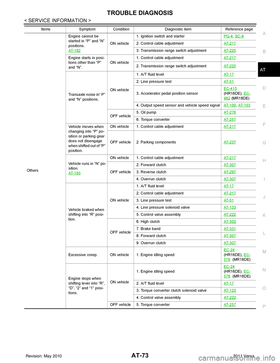
Others Engine cannot be
started in “P” and “N”
positions.
AT- 1 8 2
ON vehicle
1. Ignition switch and starter
PG-4
, SC-9
2. Control cable adjustmentAT- 2 1 7
3. Transmission range switch adjustmentAT- 2 2 5
Engine starts in posi-
tions other than “P”
and “N”.ON vehicle
1. Control cable adjustment
AT- 2 1 7
2. Transmission range switch adjustmentAT- 2 2 5
Transaxle noise in“ P”
and “N” positions.ON vehicle1. A/T fluid level
AT- 1 7
2. Line pressure testAT- 5 1
3. Accelerator pedal position sensorEC-415
(HR16DE), EC-
982 (MR18DE)
4. Output speed sensor and vehicle speed signal AT- 1 0 0
, AT- 1 5 3
OFF vehicle5. Oil pump
AT- 2 7 86. Torque converterAT- 2 5 7
Vehicle moves when
changing into “P” po-
sition or parking gear
does not disengage
when shifted out of “P”
position.ON vehicle 1. Control cable adjustment
AT- 2 1 7
OFF vehicle 2. Parking componentsAT- 2 3 7
Vehicle runs in “N” po-
sition.
AT- 1 8 3
ON vehicle 1. Control cable adjustmentAT- 2 1 7
OFF vehicle2. Forward clutch
AT- 3 0 73. Reverse clutchAT- 2 9 7
4. Overrun clutchAT- 3 0 7
Vehicle braked when
shifting into “R” posi-
tion.ON vehicle
1. A/T fluid level
AT- 1 7
2. Control cable adjustmentAT- 2 1 7
3. Line pressure testAT- 5 1
4. Line pressure solenoid valveAT- 1 3 3
5. Control valve assemblyAT- 2 2 2
OFF vehicle6. High clutch
AT- 3 0 27. Brake band AT- 3 3 1
8. Forward clutchAT- 3 0 7
9. Overrun clutchAT- 3 0 7
Excessive creep. ON vehicle 1. Engine idling speed EC-24
(HR16DE), EC-
578 (MR18DE)
Engine stops when
shifting lever into “R”,
“D”, “2” and “1” posi-
tions. ON vehicle
1. Engine idling speed
EC-24
(HR16DE), EC-
578 (MR18DE)
2. A/T fluid level AT- 1 7
3. Torque converter clutch solenoid valveAT- 1 2 3
4. Control valve assemblyAT- 2 2 2
OFF vehicle 5. Torque converter AT- 2 5 7
ItemsSymptom Condition Diagnostic itemReference page
Revision: May 2010 2011 Versa
Page 115 of 3787

AT-98
< SERVICE INFORMATION >
P0710 TRANSMISSION FLUID TEMPERATURE SENSOR A
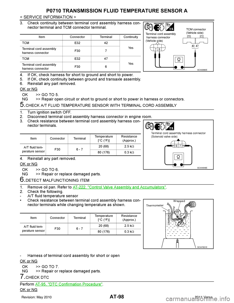
3. Check continuity between terminal cord assembly harness con-
nector terminal and TCM connector terminal.
4. If OK, check harness for short to ground and short to power.
5. If OK, check continuity bet ween ground and transaxle assembly.
6. Reinstall any part removed.
OK or NG
OK >> GO TO 5.
NG >> Repair open circuit or short to ground or short to power in harness or connectors.
5.CHECK A/T FLUID TEMPERATURE SENSO R WITH TERMINAL CORD ASSEMBLY
1. Turn ignition switch OFF.
2. Disconnect terminal cord assembly harness connector in engine room.
3. Check resistance between terminal cord assembly harness con- nector terminals.
4. Reinstall any part removed.
OK or NG
OK >> GO TO 6.
NG >> Repair or replace damaged parts.
6.DETECT MALFUNCTIONING ITEM
1. Remove oil pan. Refer to AT-222, "
Control Valve Assembly and Accumulators".
2. Check the following.
- A/T fluid temperature sensor
• Check resistance between terminal cord assembly harness con- nector terminals while changing temperature as shown.
- Harness of terminal cord assembly for short or open
OK or NG
OK >> GO TO 7.
NG >> Repair or replace damaged parts.
7.CHECK DTC
Perform AT-95, "
DTC Confirmation Procedure".
OK or NG
Item Connector Terminal Continuity
TCM E3242
Ye s
Terminal cord assembly
harness connector F30
7
TCM E3247
Ye s
Terminal cord assembly
harness connector F30
6
SCIA2660E
Item Connector Terminal Temperature
[° C ( °F)] Resistance
(Approx.)
A/T fluid tem-
perature sensor F30 6 - 7 20 (68) 2.5 k
Ω
80 (176) 0.3 kΩ
SCIA4948E
Item Connector Terminal Temperature
[° C ( °F)] Resistance
(Approx.)
A/T fluid tem-
perature sensor F30 6 - 7 20 (68) 2.5 k
Ω
80 (176) 0.3 kΩ
SCIA7831E
Revision: May 2010 2011 Versa
Page 116 of 3787

P0710 TRANSMISSION FLUID TEMPERATURE SENSOR AAT-99
< SERVICE INFORMATION >
DE
F
G H
I
J
K L
M A
B
AT
N
O P
OK >> INSPECTION END
NG >> GO TO 8.
8.CHECK TCM
1. Check TCM input/output signal. Refer to AT-75, "
TCM Terminal and Reference Value".
2. If NG, recheck TCM pin terminals for dam age or loose connection with harness connector.
OK or NG
OK >> INSPECTION END
NG >> Repair or replace damaged parts.
Component InspectionINFOID:0000000005928128
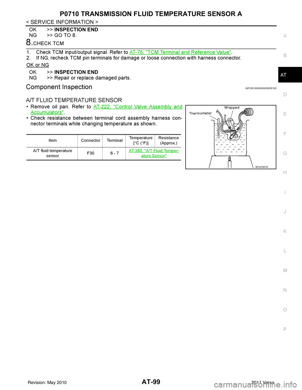
A/T FLUID TEMPERATURE SENSOR
• Remove oil pan. Refer to AT-222, "Control Valve Assembly and
Accumulators".
• Check resistance between terminal cord assembly harness con-
nector terminals while changing temperature as shown.
Item Connector Terminal Temperature
[° C ( °F)] Resistance
(Approx.)
A/T fluid temperature sensor F30 6 - 7
AT- 3 8 0 , "
A/T Fluid Temper-
ature Sensor"
SCIA7831E
Revision: May 2010
2011 Versa
Page 1056 of 3787

CVT-1
TRANSMISSION/TRANSAXLE
DE
F
G H
I
J
K L
M
SECTION CVT
A
B
CVT
N
O P
CONTENTS
CVT
RE0F08B
SERVICE INFORMATION .. ..........................
5
INDEX FOR DTC ............................................ .....5
Alphabetical Index ............................................... ......5
DTC No. Index ..........................................................5
PRECAUTIONS ...................................................7
Precaution for Supplemental Restraint System
(SRS) "AIR BAG" and "SEAT BELT PRE-TEN-
SIONER" ............................................................. ......
7
Precaution Necessary for Steering Wheel Rota-
tion After Battery Disconnect ............................... ......
7
Precaution for On Board Diagnosis (OBD) System
of CVT and Engine ....................................................
8
Service After Replacing TCM and Transaxle As-
sembly .......................................................................
8
Removal and Installation Procedure for CVT Unit
Connector ............................................................ ......
9
Precaution ...............................................................10
Service Notice or Precaution ...................................11
ATFTEMP COUNT Conversion Table ....................11
PREPARATION .............................................. ....13
Special Service Tool ........................................... ....13
Commercial Service Tool ........................................13
CVT FLUID .........................................................14
Checking CVT Fluid ............................................ ....14
Changing CVT Fluid ................................................15
CVT Fluid Cooler Cleaning .....................................15
CVT SYSTEM ................................................. ....19
Cross-Sectional View - RE0F08B ....................... ....19
Control System .................................................... ....20
Hydraulic Control System ........................................21
TCM Function ...................................................... ....21
CAN Communication ...............................................22
Input/Output Signal of TCM .....................................22
Line Pressure and Secondary Pressure Control .....23
Shift Control ............................................................23
Lock-up and Select Control .....................................25
Control Valve ....................................................... ....25
ON BOARD DIAGNOSTIC (OBD) SYSTEM ....27
Introduction ..............................................................27
OBD-II Function for CVT System ............................27
One or Two Trip Detection Logic of OBD-II .............27
OBD-II Diagnostic Trouble Code (DTC) ..................27
Malfunction Indicator Lamp (MIL) ............................28
TROUBLE DIAGNOSIS ....................................30
DTC Inspection Priority Chart ..................................30
Fail-Safe ..................................................................30
How to Perform Trouble Diagnosis for Quick and
Accurate Repair .......................................................
31
CVT Electrical Parts Location ..................................36
Circuit Diagram ........................................................37
Inspections before Trouble Diagnosis .....................37
Road Test ................................................................41
Check before Engine Is Started ...............................42
Check at Idle ............................................................42
Cruise Test ..............................................................43
Vehicle Speed When Shifting Gears .......................45
TCM Terminal and Reference Value .......................46
CONSULT-III Function (TRANSMISSION) .......... ....48
Diagnosis Procedure without CONSULT-III ............55
U1000 CAN COMM CIRCUIT ...........................56
Description ........................................................... ....56
On Board Diagnosis Logic .......................................56
Possible Cause ........................................................56
DTC Confirmation Procedure ..................................56
Wiring Diagram - CVT - CAN ...................................57
Diagnosis Procedure ...............................................58
U1010 CONTROL UNIT (CAN) .........................59
Description ...............................................................59
On Board Diagnosis Logic .......................................59
Possible Cause ........................................................59
DTC Confirmation Procedure ..................................59
Diagnosis Procedure ...............................................59
Revision: May 2010 2011 Versa
Page 1070 of 3787
![NISSAN TIIDA 2011 Service Repair Manual CVT FLUIDCVT-15
< SERVICE INFORMATION > [RE0F08B]
D
E
F
G H
I
J
K L
M A
B
CVT
N
O P
FLUID CONDITION CHECK
Changing CVT FluidINFOID:0000000005928731
1. Warm up CVT fluid by driving the vehicle for 10 m NISSAN TIIDA 2011 Service Repair Manual CVT FLUIDCVT-15
< SERVICE INFORMATION > [RE0F08B]
D
E
F
G H
I
J
K L
M A
B
CVT
N
O P
FLUID CONDITION CHECK
Changing CVT FluidINFOID:0000000005928731
1. Warm up CVT fluid by driving the vehicle for 10 m](/manual-img/5/57396/w960_57396-1069.png)
CVT FLUIDCVT-15
< SERVICE INFORMATION > [RE0F08B]
D
E
F
G H
I
J
K L
M A
B
CVT
N
O P
FLUID CONDITION CHECK
Changing CVT FluidINFOID:0000000005928731
1. Warm up CVT fluid by driving the vehicle for 10 minutes.
• : Vehicle front
• Radiator (2)
• CVT fluid cooler hose [inlet side (3)]
• Transaxle assembly (4)
2. Drain CVT fluid from CVT fluid cooler hose [outlet side (1)] and refill with new specified NISSAN CVT fluid in the CVT fluid
charging pipe with the engine running at idle speed.
CAUTION:
Only use the specifi ed NISSAN CVT fluid.
3. Refill until new CVT fluid comes out from CVT fluid cooler hose [outlet side (1)]. NOTE:
About 30 to 50% extra fluid will be required for this procedure.
4. Check fluid level and condition. Refer to CVT-14, "
Checking CVT Fluid".
CAUTION:
Delete CVT fluid deterioration date with CONSULT-III after changing CVT fluid. Refer to CVT-48,
"CONSULT-III Function (TRANSMISSION)".
CVT Fluid Cooler CleaningINFOID:0000000005928732
Whenever a CVT is repaired, overhauled, or replaced, the CVT fluid cooler mounted in the radiator must be
inspected and cleaned.
Metal debris and friction material, if present, can be trapped or become deposit in the CVT fluid cooler. This
debris can contaminate the newly serviced CVT or, in severe cases, can block or restrict the flow of CVT fluid.
In either case, malfunction of the newly serviced CVT may occur.
Debris, if present, may deposit as CVT fluid enters the cool er inlet. It will be necessary to back flush the cooler
through the cooler outlet in order to flush out any built up debris.
CVT FLUID COOLER CLEANING PROCEDURE
1. Identify the CVT inlet and outlet fluid cooler hoses.
2. Position an oil pan under the inlet and outlet cooler hoses.
Fluid status Conceivable cause Required operation
Varnished (viscous
varnish state) Clutch, brake
scorchedReplace the CVT fluid and check the
CVT main unit and the vehicle for
malfunctions (wire harness, cooler
pipes, etc.)
Milky white or cloudy Water in the fluid Replace the CVT fluid and check for places where water is getting in.
Large amount of
metal powder mixed
in fluid Unusual wear of
sliding parts within
CVTReplace the CVT fluid and check for
improper operation of the CVT.
ATA0022D
Fluid capacity and grade: Refer to
MA-14, "Fluids
and Lubricants".SCIA6088E
Revision: May 2010 2011 Versa
Page 1188 of 3787
![NISSAN TIIDA 2011 Service Repair Manual P1778 STEP MOTORCVT-133
< SERVICE INFORMATION > [RE0F08B]
D
E
F
G H
I
J
K L
M A
B
CVT
N
O P
P1778 STEP MOTOR
DescriptionINFOID:0000000005928931
• The step motor is included in the control valve asse NISSAN TIIDA 2011 Service Repair Manual P1778 STEP MOTORCVT-133
< SERVICE INFORMATION > [RE0F08B]
D
E
F
G H
I
J
K L
M A
B
CVT
N
O P
P1778 STEP MOTOR
DescriptionINFOID:0000000005928931
• The step motor is included in the control valve asse](/manual-img/5/57396/w960_57396-1187.png)
P1778 STEP MOTORCVT-133
< SERVICE INFORMATION > [RE0F08B]
D
E
F
G H
I
J
K L
M A
B
CVT
N
O P
P1778 STEP MOTOR
DescriptionINFOID:0000000005928931
• The step motor is included in the control valve assembly.
• The step motor's 4 aspects of ON/OFF change according to the signal from TCM. As a result, the flow of line pressure to primary pulley is changed and pulley ratio is controlled.
• This diagnosis item is detected when electrical system is OK, but mechanical system is NG.
• This diagnosis item is detected when the state of the changing the speed mechanism in unit does not oper- ate normally.
CONSULT-III Reference Val ue in Data Monitor ModeINFOID:0000000005928932
Remarks: Specification data are reference values.
On Board Diagnosis LogicINFOID:0000000005928933
• This is an OBD-II self-diagnostic item.
• Diagnostic trouble code “P1778” with CONSULT-III is detected under the following conditions.
- When not changing the pulley ratio according to the instruction of TCM.
Possible CauseINFOID:0000000005928934
Step motor
DTC Confirmation ProcedureINFOID:0000000005928935
CAUTION:
• Always drive vehicle at a safe speed.
• Before starting “DTC Confirmation Procedure”, confirm “Hi” or “Mid” or “Low” fixation by “PRI
SPEED” and “VEHICLE SPEED” on “DATA MONITOR MODE”.
• If hi-geared fixation occurred, go to CVT-134, "
Diagnosis Procedure".
NOTE:
If “DTC Confirmation Procedure” has been previously performed, always turn ignition switch OFF and
wait at least 10 seconds before performing the next test.
After the repair, touch “ERASE” on “SELF-DIAG RESULTS” and then perform the following procedure to con-
firm the malfunction is eliminated.
WITH CONSULT-III
1. Turn ignition switch ON and select “DATA MO NITOR” mode for “TRANSMISSION” with CONSULT-III.
2. Make sure that output voltage of CVT fluid temperature sensor is within the range below.
ATF TEMP SEN: 1.0 - 2.0 V
If out of range, drive the vehicle to decrease the voltage (warm up the fluid) or stop engine to
increase the voltage (c ool down the fluid)
3. Select “DATA MONITOR” mode for “TRANSMISSION” with CONSULT-III.
4. Start engine and maintain the following conditions for at least 30 consecutive seconds. TEST START FROM 0 km/h (0 MPH)
CONSTANT ACCELERATION: Keep 30 sec or more
VEHICLE SPEED: 10 km/h (6 MPH) or more
ACC PEDAL OPEN: More than 1.0/8
RANGE: “D” position
ENG SPEED: 450 rpm or more
5. If DTC is detected, go to CVT-134, "
Diagnosis Procedure".
WITH GST
Follow the procedure “WITH CONSULT-III”.
Item name Condition Display value (Approx.)
STM STEP During driving(−
20) - (+180) step
GEAR RATIO 2.56 - 0.43
Revision: May 2010 2011 Versa