2011 NISSAN TIIDA door lock
[x] Cancel search: door lockPage 418 of 3787
![NISSAN TIIDA 2011 Service Repair Manual AUDIOAV-21
< SERVICE INFORMATION > [AUDIO WITHOUT NAVIGATION]
C
D
E
F
G H
I
J
L
M A
B
AV
N
O P
NOTE:
Noise resulting from variations in field strength, such as fading noise and multi-path noise, or e NISSAN TIIDA 2011 Service Repair Manual AUDIOAV-21
< SERVICE INFORMATION > [AUDIO WITHOUT NAVIGATION]
C
D
E
F
G H
I
J
L
M A
B
AV
N
O P
NOTE:
Noise resulting from variations in field strength, such as fading noise and multi-path noise, or e](/manual-img/5/57396/w960_57396-417.png)
AUDIOAV-21
< SERVICE INFORMATION > [AUDIO WITHOUT NAVIGATION]
C
D
E
F
G H
I
J
L
M A
B
AV
N
O P
NOTE:
Noise resulting from variations in field strength, such as fading noise and multi-path noise, or external noise
from trains and other sources. It is not a malfunction.
• Fading noise: This noise occurs because of variations in the field strength in a narrow range due to moun-
tains or buildings blocking the signal.
• Multi-path noise: This noise results from the waves sent directly from the broadcast station arriving at the antenna at a different time from the waves t hat reflect off of mountains or buildings.
Noise InspectionINFOID:0000000005931285
The vehicle itself can be a source of noise if noise prevention parts or electrical equipment is malfunctioning.
Check if noise is caused and/or changed by engine speed, ignition switch turned to each position, and opera-
tion of each piece of electrical equipment, and determine the cause.
NOTE:
The source of the noise can be found easily by listening to the noise while removing the fuses of electrical
components, one by one.
TYPE OF NOISE AND POSSIBLE CAUSE
No sound can be heard from one or several speakers. • Open or short in audio signal circuit between audio unit and front
speaker. Refer to AV- 2 4 , "
Sound Is Not Heard from Front Door
Speaker (Base System)" or AV- 2 6 , "Sound Is Not Heard from
Front Door Speaker or Tweeter (Premium System)" .
• Front speaker. Refer to AV- 2 4 , "
Sound Is Not Heard from Front
Door Speaker (Base System)" or AV- 2 6 , "Sound Is Not Heard
from Front Door Speaker or Tweeter (Premium System)" .
• Open or short in audio signal circuit between audio unit and rear
speaker. Refer to AV- 2 5 , "
Sound Is Not Heard from Rear Door
Speaker (Base System)" or AV- 2 7 , "Sound Is Not Heard from
Rear Door Speaker (Premium System)" .
• Rear speaker. Refer to AV- 2 5 , "
Sound Is Not Heard from Rear
Door Speaker (Base System)" or AV- 2 7 , "Sound Is Not Heard
from Rear Door Speaker (Premium System)" .
• Tweeter (mid level and premium system) AV- 2 6 , "
Sound Is Not
Heard from Front Door Speaker or Tweeter (Premium System)"
or AV- 2 7 , "
Sound Is Not Heard from Rear Door Speaker (Premi-
um System)" .
• Audio unit. Refer to AV- 2 9 , "
Removal and Installation" .
No sound can be heard from radio or noise is heard. • Antenna feeder. Refer to
AV- 3 3 , "
Location of Antenna" .
• Antenna. Refer to AV- 3 3 , "
Location of Antenna" .
• Audio unit. Refer to AV- 2 9 , "
Removal and Installation" .
Symptom
Check item
Occurrence condition Possible cause
Occurs only when engine is ON. A continuous growling noise occurs. The speed of
the noise varies with changes in the engine speed.
Ignition components
A whistling noise occurs while the engine speed is
high. A booming noise occurs while the engine is
running and the lighting switch is ON. Generator
Noise only occurs when various
electrical components are oper-
ating. A cracking or snapping sound occurs with the op-
eration of various switches.
Relay malfunction, radio malfunction
The noise occurs when various motors are operat-
ing. • Motor case ground
•Motor
The noise occurs constantly, not just under certain conditions. • Rear defogger coil malfunction
• Open circuit in printed heater
A cracking or snapping sound occurs while the vehicle is being driven, especially when
it is vibrating excessively. • Ground wire of body parts.
• Ground due to improper part installation
• Wiring connections or a short circuit
Revision: May 2010
2011 Versa
Page 451 of 3787
![NISSAN TIIDA 2011 Service Repair Manual AV-54
< SERVICE INFORMATION >[AUDIO WITH NAVIGATION]
AUDIO
System Description
INFOID:0000000006216702
AUDIO SYSTEM
Refer to Owners Manual for audio system operating instructions.
Navigation is built NISSAN TIIDA 2011 Service Repair Manual AV-54
< SERVICE INFORMATION >[AUDIO WITH NAVIGATION]
AUDIO
System Description
INFOID:0000000006216702
AUDIO SYSTEM
Refer to Owners Manual for audio system operating instructions.
Navigation is built](/manual-img/5/57396/w960_57396-450.png)
AV-54
< SERVICE INFORMATION >[AUDIO WITH NAVIGATION]
AUDIO
System Description
INFOID:0000000006216702
AUDIO SYSTEM
Refer to Owner's Manual for audio system operating instructions.
Navigation is built into AV control unit.
This navigation has the following functions.
• Full support for playback of music from iPod
® and USB device.
• High resolution full color touch panel 5 “WQVGA” display.
• FM/AM twin digital tuner.
• USB mass storage.
•XM traffic.
• POI Support is included. User POI download.
Power is supplied at all times
• through 20A fuse (No. 27, located in the fuse and fusible link box)
• to AV control unit terminal 19.
With the ignition switch in the ACC or ON position, power is supplied
• through 10A fuse [No. 20, located in the fuse block (J/B)]
• to AV control unit terminal 7.
Ground is supplied to
• to AV control unit terminals 20 and 32
• through grounds M57 and M61.
Then audio signals are supplied
• through AV control unit terminals 2, 3, 4, 5, 11, 12, 13 and 14
• to terminals + and - of front door speaker LH and RH
• to terminals + and - of front tweeter LH and RH and
• to terminals + and - of rear door speaker LH and RH.
STEERING WHEEL AUDIO CONTROL SWITCHES
When one of steering wheel audio control switches is pus hed, the resistance in steering switch circuit changes
depending on which button is pushed.
AWNIA2215GB
Revision: May 2010 2011 Versa
Page 497 of 3787

BCM (BODY CONTROL MODULE)BCS-7
< SERVICE INFORMATION >
C
DE
F
G H
I
J
L
M A
B
BCS
N
O P
• When CAN communication operation is detected, it switches to CAN communication status.
• When a state of the following switches changes , it switches to CAN communication state:
- Ignition switch
- Key switch (without Intelligent Key)
- Key switch and ignition knob switch (with Intelligent Key)
- Hazard switch
- Door lock/unlock switch (with power door locks)
- Front door switch (LH, RH)
- Rear door switch (LH, RH)
- Back door lock assembly (Hatchback)
- Trunk key cylinder switch (Sedan)
- Trunk lamp switch and trunk release solenoid (Sedan)
- Combination switch (passing, lighting switch 1st position, front fog lamp)
- Keyfob (lock/unlock signal) (with power door locks)
- Front door key cylinder switch LH
• When control performed only by BCM is required by switch, it shifts to CAN communication inactive mode.
• Status of combination switch reading function is changed.
SYSTEMS CONTROLLED BY BCM DIRECTLY
• Power door lock system (with power door locks). Refer to BL-23, "System Description" .
• Remote keyless entry system. Refer to BL-58, "
System Description" .
• Power window system (with power windows). Refer to GW-19, "
System Description" . NOTE
• Sunroof system (with sunroof). Refer to RF-11, "System Description". NOTE
• Room lamp timer. Refer to LT-93, "System Description" .
• Rear wiper and washer system (Hatchback). Refer to WW-27, "
System Description" .
NOTE:
Power supply only. No system control.
SYSTEMS CONTROLLED BY BCM AND IPDM E/R
• Panic system. Refer to BL-58, "System Description" .
• Vehicle security (theft warning) system. Refer to BL-218, "
System Description" .
• NVIS(NATS) system. Refer to BL-246, "
System Description" .
• Headlamp, tail lamp and battery saver control systems. Refer to LT-74, "
System Description", LT- 5 , "System
Description" or LT-27, "System Description" .
• Front fog lamp (with front fog lamps). Refer to LT-41, "
System Description" .
• Front wiper and washer system. Refer to WW-5, "
System Description" .
• Rear window defogger system. Refer to GW-51, "
System Description" .
SYSTEMS CONTROLLED BY BCM AND COMBINATION METER
• Warning chime. Refer to DI-43, "System Description" .
• Turn signal and hazard warning lamps. Refer to LT-50, "
System Description" .
SYSTEMS CONTROLLED BY BCM AND INTELLIGENT KEY UNIT (WITH INTELLIGENT KEY)
• Intelligent Key system. Refer to BL-88, "System Description" .
MAJOR COMPONENTS AND CONTROL SYSTEM
System Input Output
Remote keyless entry system (with
power door locks) Remote keyless entry receiver
(keyfob)• All door locking actuators
• Turn signal lamp (LH, RH)
• Combination meter (turn signal lamp)
Intelligent Key system (with Intelligent
Key) Intelligent Key unit• All door locking actuators
• Turn signal lamp (LH, RH)
• Combination meter (turn signal lamp)
Power door lock system (with power
door locks) Front power door lock/unlock
switch (LH, RH)
All door locking actuators
Power supply (IGN /RAP) to power
window (with power windows) Ignition retained power supply Power supply to power window and sunroof system
Power supply (BAT) to power window
(with power windows) Battery power supply
Power supply to power window and sunroof system
Revision: May 2010 2011 Versa
Page 498 of 3787

BCS-8
< SERVICE INFORMATION >
BCM (BODY CONTROL MODULE)
CAN Communication System Description
INFOID:0000000005929256
Refer to LAN-7, "System Description".
Panic alarm •Key switch
•KeyfobIPDM E/R
Vehicle security system • All door switches
•Keyfob
• Door lock/unlock switch
• Trunk key cylinder switch (Se-
dan)
• Front door key cylinder switch LH • IPDM/ER
• Security indicator lamp
Battery save r control • Ignition switch
• Combination switch
IPDM E/R
Headlamp Combination switch IPDM E/R
Tail lamp Combination switchIPDM E/R
Front fog lamp (with front fog lamps) Combination switch IPDM E/R
Turn signal lamp Combination switch• Turn signal lamp
• Combination meter
Hazard lamp Hazard switch• Turn signal lamp
• Combination meter
Room lamp timer •Key switch
•Keyfob
• Main power window and door
lock/unlock switch
• Front door switch LH
• All door switch Interior room lamp
Back door switch signal (Hatchback) Back door lock assembly Luggage room lamp
Back door lock signal (Hatchback) Back door lock assembly Back door opener
Trunk lamp switch signal (Sedan) Trunk lamp switch and trunk re-
lease solenoidLuggage room lamp
Trunk lid opener signal (Sedan) Trunk lamp switch and trunk re-
lease solenoid
Trunk lid opener
Key warning chime •Key switch
• Front door switch LHCombination meter (warning buzzer)
Light warning chime • Combination switch
•Key switch
• Front door switch LHCombination meter (warning buzzer)
Seat belt warning chime • Seat belt buckle switch LH
• Ignition switch
Combination meter (warning buzzer)
Front wiper and washer system • Combination switch
• Ignition switchIPDM E/R
Rear window defogger Rear window defogger switch IPDM E/R
Rear wiper and washer system
(Hatchback) • Combination switch
• Ignition switch
Rear wiper motor
A/C switch signal Front air controlECM
Blower fan switch signal Front air controlECM
A/C indicator signal Front air controlA/C indicator
Low tire pressure warning system Remote keyless entry receiver Combination meter System
Input Output
Revision: May 2010 2011 Versa
Page 502 of 3787

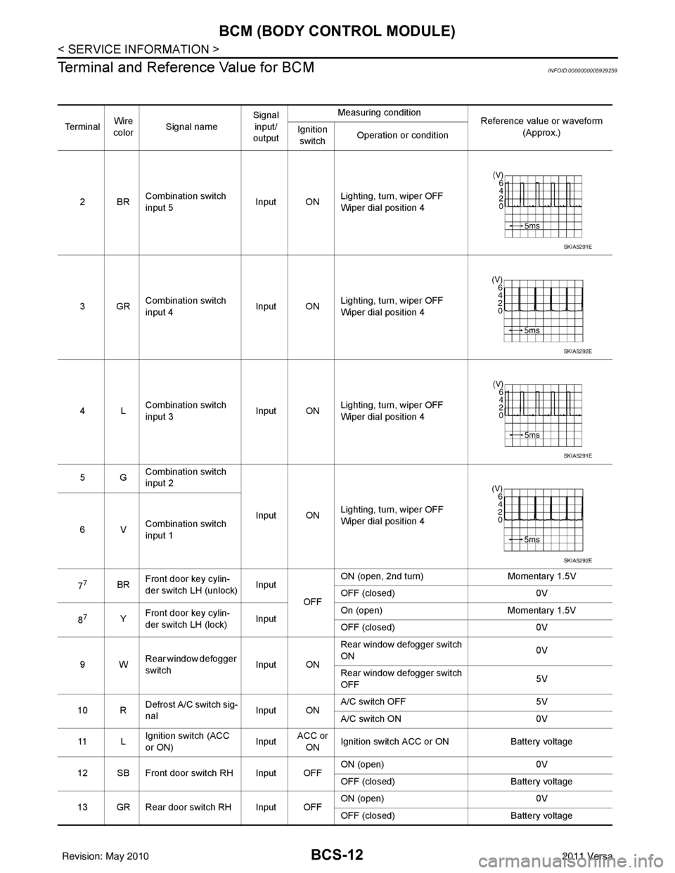
BCS-12
< SERVICE INFORMATION >
BCM (BODY CONTROL MODULE)
Terminal and Reference Value for BCM
INFOID:0000000005929259
Te r m i n a l Wire
color Signal name Signal
input/
output Measuring condition
Reference value or waveform
(Approx.)
Ignition
switch Operation or condition
2BR Combination switch
input 5
Input ONLighting, turn, wiper OFF
Wiper dial position 4
3GR Combination switch
input 4 Input ONLighting, turn, wiper OFF
Wiper dial position 4
4L Combination switch
input 3
Input ONLighting, turn, wiper OFF
Wiper dial position 4
5G Combination switch
input 2
Input ONLighting, turn, wiper OFF
Wiper dial position 4
6V Combination switch
input 1
7
7BR Front door key cylin-
der switch LH (unlock) Input
OFFON (open, 2nd turn)
Momentary 1.5V
OFF (closed) 0V
8
7Y Front door key cylin-
der switch LH (lock) InputOn (open)
Momentary 1.5V
OFF (closed) 0V
9W Rear window defogger
switch Input ONRear window defogger switch
ON
0V
Rear window defogger switch
OFF 5V
10 R Defrost A/C switch sig-
nal
Input ONA/C switch OFF
5V
A/C switch ON 0V
11 L Ignition switch (ACC
or ON) InputACC or
ON Ignition switch ACC or ON
Battery voltage
12 SB Front door switch RH Input OFF ON (open)
0V
OFF (closed) Battery voltage
13 GR Rear door switch RH Input OFF ON (open)
0V
OFF (closed) Battery voltage
SKIA5291E
SKIA5292E
SKIA5291E
SKIA5292E
Revision: May 2010 2011 Versa
Page 504 of 3787

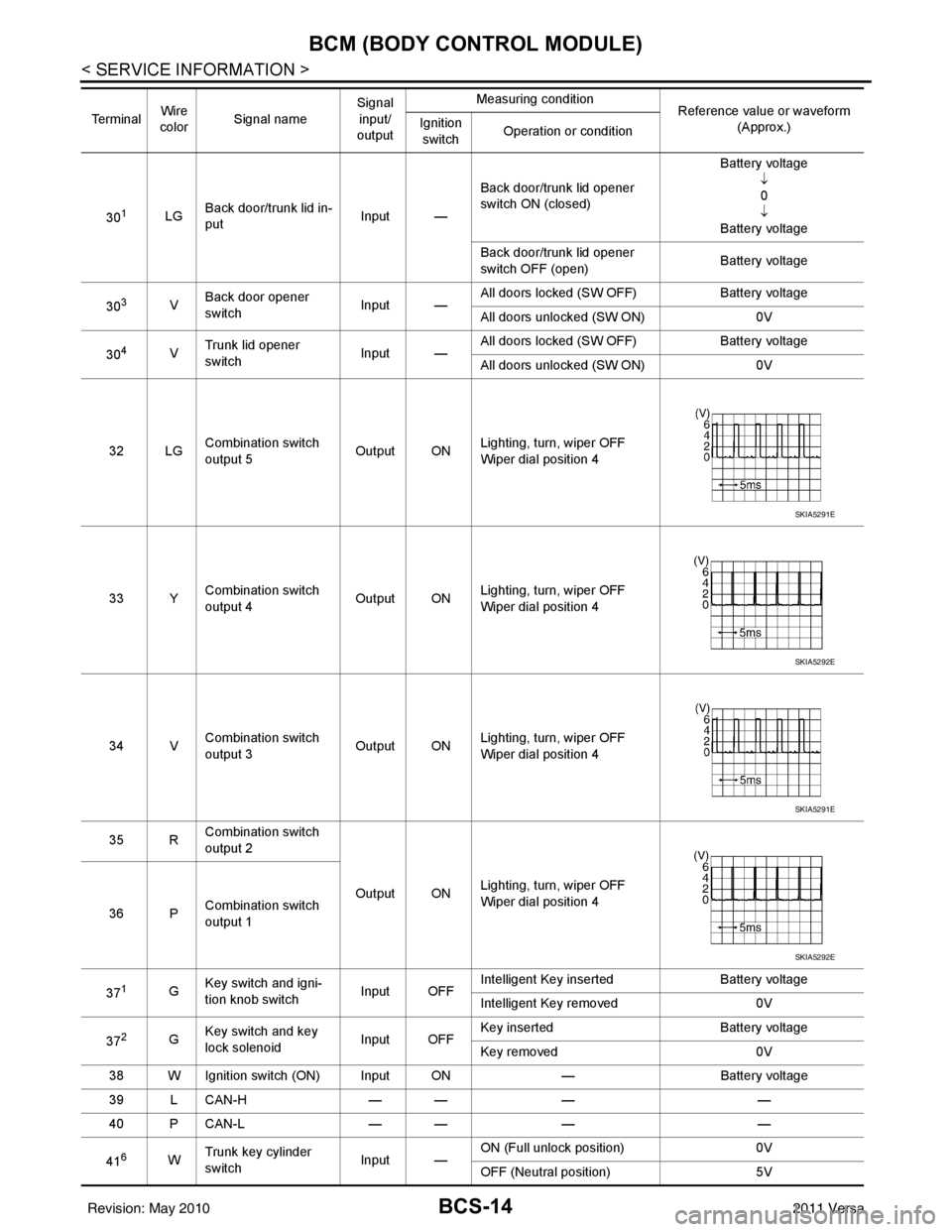
BCS-14
< SERVICE INFORMATION >
BCM (BODY CONTROL MODULE)
301LGBack door/trunk lid in-
put Input —Back door/trunk lid opener
switch ON (closed) Battery voltage
↓0
↓
Battery voltage
Back door/trunk lid opener
switch OFF (open) Battery voltage
30
3V Back door opener
switch
Input —All doors locked (SW OFF)
Battery voltage
All doors unlocked (SW ON) 0V
30
4V Trunk lid opener
switch
Input —All doors locked (SW OFF)
Battery voltage
All doors unlocked (SW ON) 0V
32 LG Combination switch
output 5 Output ONLighting, turn, wiper OFF
Wiper dial position 4
33 Y Combination switch
output 4 Output ON
Lighting, turn, wiper OFF
Wiper dial position 4
34 V Combination switch
output 3
Output ONLighting, turn, wiper OFF
Wiper dial position 4
35 R Combination switch
output 2
Output ONLighting, turn, wiper OFF
Wiper dial position 4
36 P Combination switch
output 1
37
1G Key switch and igni-
tion knob switch Input OFFIntelligent Key inserted
Battery voltage
Intelligent Key removed 0V
37
2G Key switch and key
lock solenoid Input OFFKey inserted
Battery voltage
Key removed 0V
38 W Ignition switch (ON) Input ON —Battery voltage
39 L CAN-H — —— —
40 P CAN-L — —— —
41
6W Trunk key cylinder
switch
Input —ON (Full unlock position)
0V
OFF (Neutral position) 5V
Te r m i n a l
Wire
color Signal name Signal
input/
output Measuring condition
Reference value or waveform
(Approx.)
Ignition
switch Operation or condition
SKIA5291E
SKIA5292E
SKIA5291E
SKIA5292E
Revision: May 2010
2011 Versa
Page 505 of 3787

BCM (BODY CONTROL MODULE)BCS-15
< SERVICE INFORMATION >
C
DE
F
G H
I
J
L
M A
B
BCS
N
O P
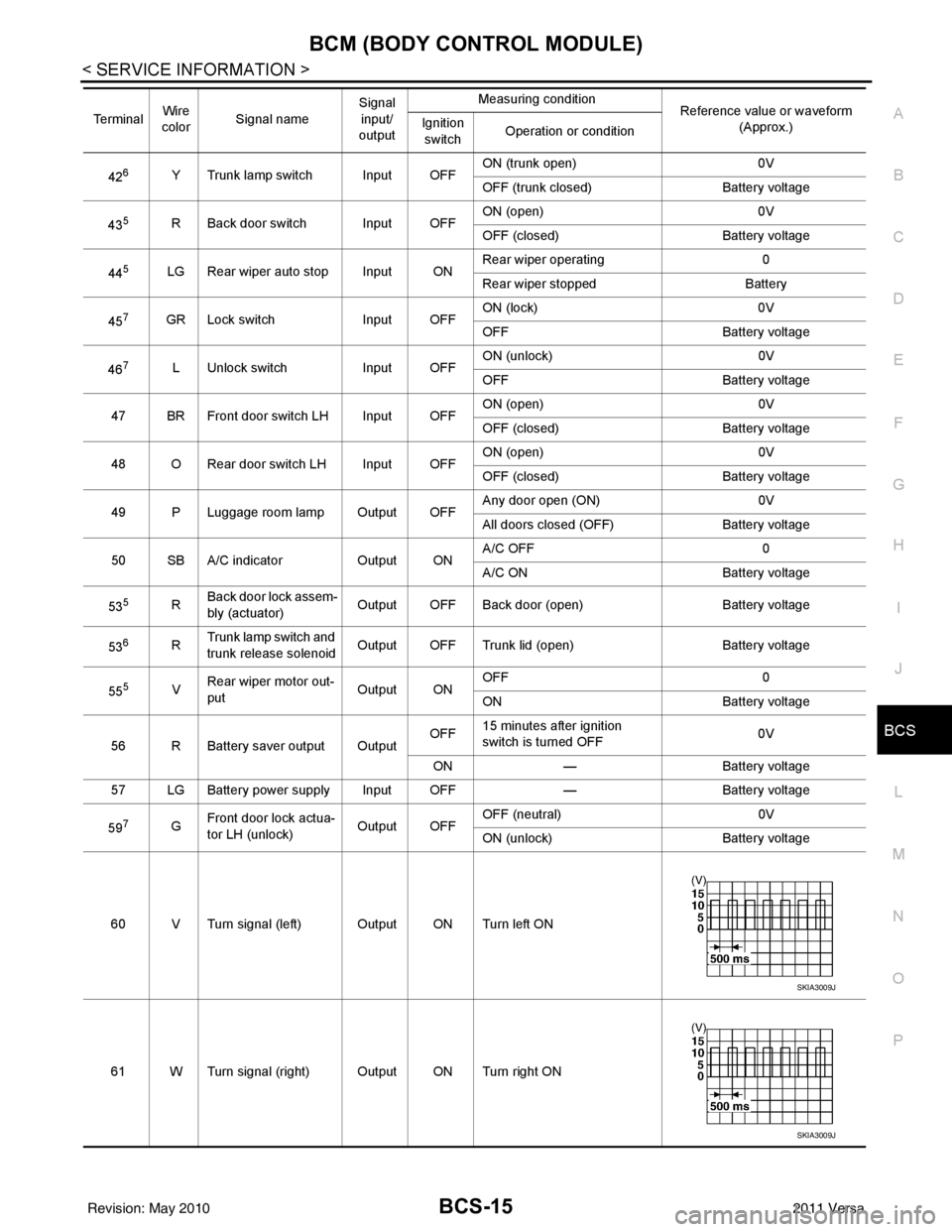
426Y Trunk lamp switch Input OFF ON (trunk open)
0V
OFF (trunk closed) Battery voltage
43
5R Back door switch Input OFF ON (open) 0V
OFF (closed)
Battery voltage
44
5LG Rear wiper auto stop Input ON Rear wiper operating 0
Rear wiper stopped
Battery
45
7GR Lock switch Input OFFON (lock)
0V
OFF Battery voltage
46
7L Unlock switch Input OFFON (unlock)
0V
OFF Battery voltage
47 BR Front door switch LH Input OFF ON (open)
0V
OFF (closed) Battery voltage
48 O Rear door switch LH Input OFF ON (open)
0V
OFF (closed) Battery voltage
49 P Luggage room lamp Output OFF Any door open (ON)
0V
All doors closed (OFF) Battery voltage
50 SB A/C indicator Output ONA/C OFF
0
A/C ON Battery voltage
53
5R Back door lock assem-
bly (actuator)
Output OFF Back door (open)
Battery voltage
53
6R Trunk lamp switch and
trunk release solenoid Output OFF Trunk lid (open)
Battery voltage
55
5V Rear wiper motor out-
put
Output ONOFF
0
ON Battery voltage
56 R Battery saver output Output OFF
15 minutes after ignition
switch is turned OFF 0V
ON — Battery voltage
57 LG Battery power supply Input OFF —Battery voltage
59
7G Front door lock actua-
tor LH (unlock)
Output OFFOFF (neutral)
0V
ON (unlock) Battery voltage
60 V Turn signal (left) Output ON Turn left ON
61 W Turn signal (right) Output ON Turn right ON
Te r m i n a l
Wire
color Signal name Signal
input/
output Measuring condition
Reference value or waveform
(Approx.)
Ignition
switch Operation or condition
SKIA3009J
SKIA3009J
Revision: May 2010
2011 Versa
Page 506 of 3787

BCS-16
< SERVICE INFORMATION >
BCM (BODY CONTROL MODULE)
1: With Intelligent Key
2: Without Intelligent Key
3: Hatchback without Intelligent Key
4: Sedan without Intelligent Key
5: Hatchback
6: Sedan
7: With power door locks
8: With power windows
BCM Power Supply and Ground Circuit InspectionINFOID:0000000005929260
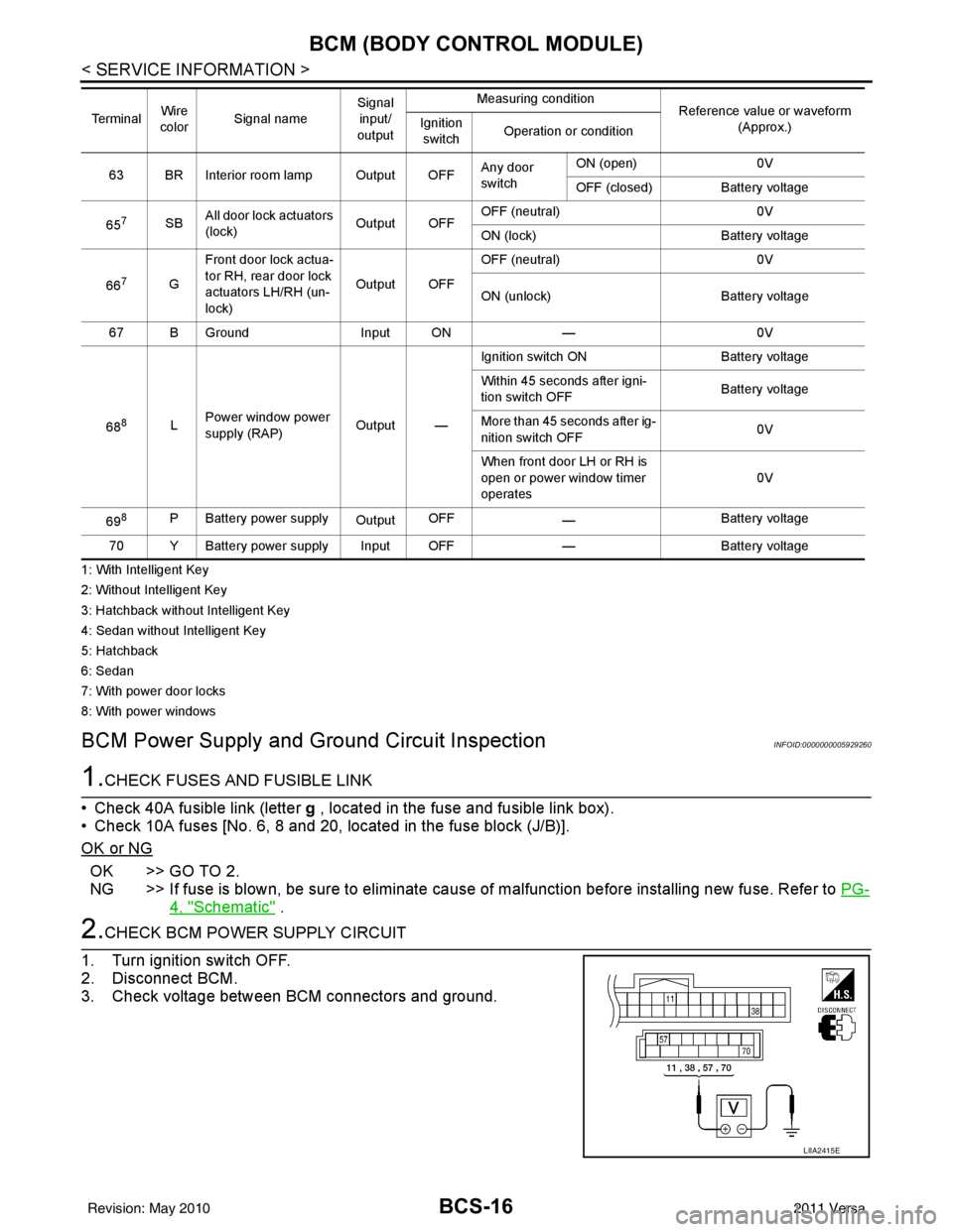
1.CHECK FUSES AND FUSIBLE LINK
• Check 40A fusible link (letter g , located in the fuse and fusible link box).
• Check 10A fuses [No. 6, 8 and 20, lo cated in the fuse block (J/B)].
OK or NG
OK >> GO TO 2.
NG >> If fuse is blown, be sure to eliminate cause of malfunction before installing new fuse. Refer to PG-
4, "Schematic" .
2.CHECK BCM POWER SUPPLY CIRCUIT
1. Turn ignition switch OFF.
2. Disconnect BCM.
3. Check voltage between BCM connectors and ground.
63 BR Interior room lamp Output OFF Any door
switchON (open)
0V
OFF (closed) Battery voltage
65
7SB All door lock actuators
(lock) Output OFFOFF (neutral)
0V
ON (lock) Battery voltage
66
7G Front door lock actua-
tor RH, rear door lock
actuators LH/RH (un-
lock) Output OFFOFF (neutral)
0V
ON (unlock) Battery voltage
67 B Ground Input ON—0V
68
8L Power window power
supply (RAP)
Output —Ignition switch ON
Battery voltage
Within 45 seconds after igni-
tion switch OFF Battery voltage
More than 45 seconds after ig-
nition switch OFF 0V
When front door LH or RH is
open or power window timer
operates 0V
69
8P Battery power supply OutputOFF
— Battery voltage
70 Y Battery power supply Input OFF —Battery voltage
Te r m i n a l
Wire
color Signal name Signal
input/
output Measuring condition
Reference value or waveform
(Approx.)
Ignition
switch Operation or condition
LIIA2415E
Revision: May 2010
2011 Versa