2011 NISSAN TIIDA door
[x] Cancel search: doorPage 2762 of 3787

GW-8
< SERVICE INFORMATION >
SQUEAK AND RATTLE TROUBLE DIAGNOSES
SILICONE GREASE
Used instead of UHMW tape that will be visible or not fit.
Note: Will only last a few months.
SILICONE SPRAY
Use when grease cannot be applied.
DUCT TAPE
Use to eliminate movement.
CONFIRM THE REPAIR
Confirm that the cause of a noise is repaired by test driving the vehicle. Operate the vehicle under the same
conditions as when the noise originally occurred. Refer to the notes on the Diagnostic Worksheet.
Generic Squeak and Rattle TroubleshootingINFOID:0000000005929463
Refer to Table of Contents for specific component removal and installation information.
INSTRUMENT PANEL
Most incidents are caused by contact and movement between:
1. The cluster lid A and instrument panel
2. Acrylic lens and combination meter housing
3. Instrument panel to front pillar garnish
4. Instrument panel to windshield
5. Instrument panel mounting pins
6. Wiring harnesses behind the combination meter
7. A/C defroster duct and duct joint
These incidents can usually be located by tapping or moving the components to duplicate the noise or by
pressing on the components while driving to stop the noise. Most of these incidents can be repaired by apply-
ing felt cloth tape or silicone spray (in hard to reach areas). Urethane pads can be used to insulate wiring har-
ness.
CAUTION:
Do not use silicone spray to isolate a squeak or rattle. If you saturate the ar ea with silicone, you will
not be able to recheck the repair.
CENTER CONSOLE
Components to pay attention to include:
1. Shift selector cover to finisher
2. A/C control unit and cluster lid C
3. Wiring harnesses behind audio and A/C control unit
The instrument panel repair and isolation pr ocedures also apply to the center console.
DOORS
Pay attention to the:
1. Finisher and inner panel making a slapping noise
2. Inside handle escutcheon to door finisher
3. Wiring harnesses tapping
4. Door striker out of alignment causing a popping noise on starts and stops
Tapping or moving the components or pressing on them wh ile driving to duplicate the conditions can isolate
many of these incidents. You can usually insulate the areas with felt cloth tape or insulator foam blocks from
the NISSAN Squeak and Rattle Kit (J-43980) to repair the noise.
TRUNK
Trunk noises are often caused by a loose jack or loose items put into the trunk by the owner.
In addition look for:
1. Trunk lid bumpers out of adjustment
2. Trunk lid striker out of adjustment
3. The trunk lid torsion bars knocking together
4. A loose license plate or bracket
Revision: May 2010 2011 Versa
Page 2767 of 3787

WINDSHIELD GLASSGW-13
< SERVICE INFORMATION >
C
DE
F
G H
J
K L
M A
B
GW
N
O P
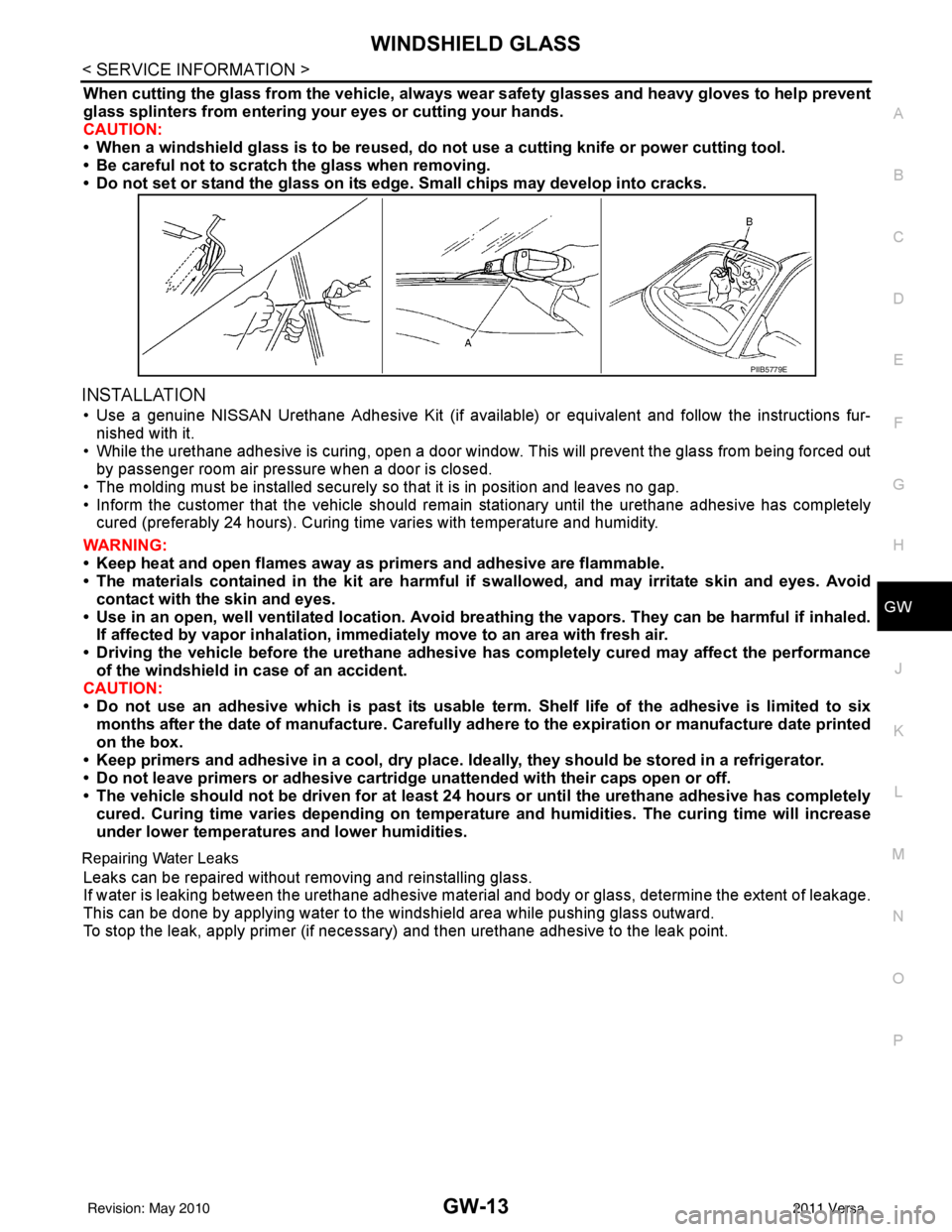
When cutting the glass from the vehicle, always wear safety glasses and heavy gloves to help prevent
glass splinters from entering your eyes or cutting your hands.
CAUTION:
• When a windshield glass is to be reused, do no t use a cutting knife or power cutting tool.
• Be careful not to scratch the glass when removing.
• Do not set or stand the glass on its ed ge. Small chips may develop into cracks.
INSTALLATION
• Use a genuine NISSAN Urethane Adhesive Kit (if availabl e) or equivalent and follow the instructions fur-
nished with it.
• While the urethane adhesive is curing, open a door window . This will prevent the glass from being forced out
by passenger room air pressure when a door is closed.
• The molding must be installed securely so that it is in position and leaves no gap.
• Inform the customer that the vehicle should rema in stationary until the urethane adhesive has completely
cured (preferably 24 hours). Curing time varies with temperature and humidity.
WARNING:
• Keep heat and open flames away as primers and adhesive are flammable.
• The materials contained in the kit are harmful if swallowed, and may irritate skin and eyes. Avoid
contact with the skin and eyes.
• Use in an open, well ventilated lo cation. Avoid breathing the vapors. They can be harmful if inhaled.
If affected by vapor inhalation, imme diately move to an area with fresh air.
• Driving the vehicle before the urethane adhesive has completely cured may affect the performance
of the windshield in case of an accident.
CAUTION:
• Do not use an adhesive which is past its usable term. Shelf life of the adhesive is limited to six
months after the date of manufacture. Carefully ad here to the expiration or manufacture date printed
on the box.
• Keep primers and adhesive in a cool, dry place. Id eally, they should be stored in a refrigerator.
• Do not leave primers or adhesive cartridge unattended with their caps open or off.
• The vehicle should not be driven for at least 24 hours or until the urethane adhesive has completely
cured. Curing time varies depend ing on temperature and humidities. The curing time will increase
under lower temperatures and lower humidities.
Repairing Water Leaks
Leaks can be repaired without removing and reinstalling glass.
If water is leaking between the urethane adhesive material and body or glass, determine the extent of leakage.
This can be done by applying water to the windshield area while pushing glass outward.
To stop the leak, apply primer (if necessary ) and then urethane adhesive to the leak point.
PIIB5779E
Revision: May 2010 2011 Versa
Page 2768 of 3787

GW-14
< SERVICE INFORMATION >
OPERA WINDOW GLASS
OPERA WINDOW GLASS
Removal and InstallationINFOID:0000000005929466
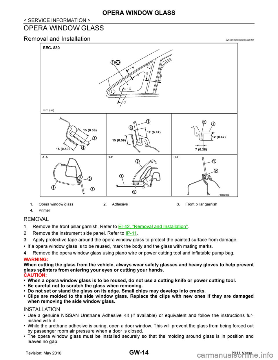
REMOVAL
1. Remove the front pillar garnish. Refer to EI-42, "Removal and Installation".
2. Remove the instrument side panel. Refer to IP-11
.
3. Apply protective tape around the opera window glas s to protect the painted surface from damage.
• If a opera window glass is to be reused, mark the body and the glass with mating marks.
4. Remove the opera window glass using piano wire or power cutting tool and inflatable pump bag.
WARNING:
When cutting the glass from the vehicle, always wear safety glasses and heavy gloves to help prevent
glass splinters from entering your eyes or cutting your hands.
CAUTION:
• When a opera window glass is to be reused, do not use a cutting knife or power cutting tool.
• Be careful not to scratch the glass when removing.
• Do not set or stand the glass on its edge. Small chips may develop into cracks.
• Clips are molded to the side window glass. Re place the clips with new ones if they are damaged
when removing the side window glass.
INSTALLATION
• Use a genuine NISSAN Urethane Adhesive Kit (if available) or equivalent and follow the instructions fur- nished with it.
• While the urethane adhesive is curing, open a door window . This will prevent the glass from being forced out
by passenger room air pressure when a door is closed.
• The opera window glass must be installed securely so that the molding around glass is in position and
leaves no gap.
PIIB6286E
1. Opera window glass 2. Adhesive3. Front pillar garnish
4. Primer
Revision: May 2010 2011 Versa
Page 2770 of 3787

GW-16
< SERVICE INFORMATION >
REAR WINDOW GLASS AND MOLDING
REAR WINDOW GLASS AND MOLDING
Removal and InstallationINFOID:0000000005929467
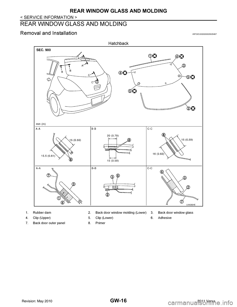
Hatchback
LIIA2924E
1. Rubber dam2. Back door window molding (Lower) 3. Back door window glass
4. Clip (Upper) 5. Clip (Lower) 6. Adhesive
7. Back door outer panel 8. Primer
Revision: May 2010 2011 Versa
Page 2772 of 3787

GW-18
< SERVICE INFORMATION >
REAR WINDOW GLASS AND MOLDING
INSTALLATION
Installation is in the reverse order of removal.
• Use a genuine NISSAN Urethane Adhesive Kit (if available) or equivalent and follow the instructions fur-nished with it.
• While the urethane adhesive is curing, open a door window . This will prevent the glass from being forced out
by passenger compartment air pressure when a door is closed.
• The molding must be installed securely so that it is in position and leaves no gap.
• Check gap along bottom to confirm that glass does not contact sheet metal.
• Inform the customer that the vehicle should rema in stationary until the urethane adhesive has completely
cured (preferably 24 hours). Curing time varies with temperature and humidity.
WARNING:
• Keep heat and open flames away as primers and adhesive are flammable.
• The materials contained in the kit are harmful if swallowed, and may irritate skin and eyes. Avoid
contact with the skin and eyes.
• Use in an open, well ventilated location. Avoid breathing the vapors. They can be harmful if inhaled. If affected by vapor inhalation, imme diately move to an area with fresh air.
• Driving the vehicle before the urethane adhesive has completely cured may affect the performance of the windshield in case of an accident.
CAUTION:
• Do not use an adhesive which is past its usable te rm. Shelf life of this product is limited to six
months after the date of manufacture. Carefully a dhere to the expiration or manufacture date printed
on the box.
• Keep primers and adhesive in a c ool, dry place. Ideally, they should be stored in a refrigerator.
• Do not leave primers or adhesive cartridge unattended with their caps open or off.
• The vehicle should not be driven for at least 24 hours or until the urethane adhesive has completely
cured. Curing time varies depe nding on temperature and humidity . The curing time will increase
under lower temperatures and lower humidities.
Repairing Water leaks for Rear Window Glass
Leaks can be repaired without removing or reinstalling glass.
If water is leaking between urethane adhesive material and body or glass, determine the extent of leakage.
This can be done by applying water to the rear window area while pushing glass outward.
To stop leak, apply primer (if necessary) and then urethane adhesive to the leak point.
Revision: May 2010 2011 Versa
Page 2773 of 3787

POWER WINDOW SYSTEMGW-19
< SERVICE INFORMATION >
C
DE
F
G H
J
K L
M A
B
GW
N
O P
POWER WINDOW SYSTEM
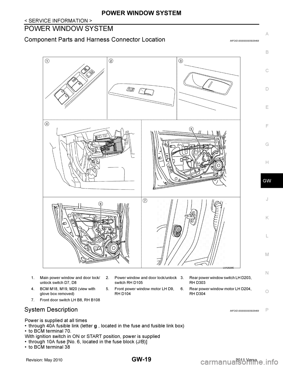
Component Parts and Har ness Connector LocationINFOID:0000000005929468
System DescriptionINFOID:0000000005929469
Power is supplied at all times
• through 40A fusible link (letter g , located in the fuse and fusible link box)
• to BCM terminal 70.
With ignition switch in ON or START position, power is supplied
• through 10A fuse [No. 6, located in the fuse block (J/B)]
• to BCM terminal 38
1. Main power window and door lock/
unlock switch D7, D8 2. Power window and door lock/unlock
switch RH D105 3. Rear power window switch LH D203,
RH D303
4. BCM M18, M19, M20 (view with glove box removed) 5. Front power window motor LH D9,
RH D104 6. Rear power window motor LH D204,
RH D304
7. Front door switch LH B8, RH B108
LIIA2529E
Revision: May 2010 2011 Versa
Page 2774 of 3787

GW-20
< SERVICE INFORMATION >
POWER WINDOW SYSTEM
• through BCM terminal 68
• to main power window and door lock/unlock switch terminal 10
• to power window and door lock/unlock switch RH terminal 8 and
• to rear power window switches LH and RH terminal 1.
Ground is supplied
• to BCM terminal 67
• to main power window and door lock/unlock switch terminal 17 and
• to power window and door lock/unlock switch RH terminal 3
• through body grounds M57 and M61.
With ignition switch in ACC or ON position, power is supplied
• through 10A fuse [No. 20, located in the fuse block (J/B)]
• to BCM terminal 11.
MANUAL OPERATION
Front Door LH
WINDOW UP
When the front LH switch in the main power window and door lock/unlock switch is pulled in the up position,
power is supplied
• through main power window and door lock/unlock switch terminal 8
• to front power window motor LH terminal 2.
Ground is supplied
• through main power window and door lock/unlock switch terminal 11
• to front power window motor LH terminal 3.
Then, the motor raises the window until the switch is released.
WINDOW DOWN
When the front LH switch in the main power window and door lock/unlock switch is pressed in the down posi-
tion, power is supplied
• through main power window and door lock/unlock switch terminal 11
• to front power window motor LH terminal 3.
Ground is supplied
• through main power window and door lock/unlock switch terminal 8
• to front power window motor LH terminal 2.
Then, the motor lowers the window until the switch is released.
Front Door RH
POWER WINDOW AND DOOR LOCK/ UNLOCK SWITCH RH OPERATION
WINDOW UP
When the power window and door lock/unlock switch RH is pulled in the up position, power is supplied
• through power window and door lock/unlock switch RH terminal 7
• to front power window motor RH terminal 2.
Ground is supplied
• through power window and door lock/unlock switch RH terminal 6
• to front power window motor RH terminal 1.
Then, the motor raises the window until the switch is released.
WINDOW DOWN
When the power window and door lock/unlock switch RH is pressed in the down position, power is supplied
• through power window and door lock/unlock switch RH terminal 6
• to front power window motor RH terminal 1.
Ground is supplied
• through power window and door lock/unlock switch RH terminal 7
• to front power window motor RH terminal 2.
Then, the motor lowers the window until the switch is released.
MAIN POWER WINDOW AND DOOR LOCK/UNLOCK SWITCH OPERATION
WINDOW UP
When the main power window and door lock/unlock switch (front RH) is pulled in the up position, power is sup-
plied
• through main power window and door lock/unlock switch terminal 16
• to power window and door lock/unlock switch RH terminal 12
• through power window and door lock/unlock switch RH terminal 7
• to front power window motor RH terminal 2.
Ground is supplied
Revision: May 2010 2011 Versa
Page 2775 of 3787

POWER WINDOW SYSTEMGW-21
< SERVICE INFORMATION >
C
DE
F
G H
J
K L
M A
B
GW
N
O P
• through main power window and door lock/unlock switch terminal 12
• to power window and door lock/unlock switch RH terminal 11
• through power window and door lock/unlock switch LH terminal 6
• to front power window motor RH terminal 1.
Then, the motor raises the window until the switch is released.
WINDOW DOWN
When the main power window and door lock/unlock switch (f ront RH) is pressed in the down position, power is
supplied
• through main power window and door lock/unlock switch terminal 12
• to power window and door lock/unlock switch LH terminal 11
• through power window and door lock/unlock switch LH terminal 6
• to front power window motor RH terminal 1.
Ground is supplied
• through main power window and door lock/unlock switch terminal 16
• to power window and door lock/unlock switch RH terminal 12
• through power window and door lock/unlock switch LH terminal 7
• to front power window motor RH terminal 2.
Then, the motor lowers the window until the switch is released.
Rear Door (LH or RH)
REAR POWER WINDOW SWITCH LH OR RH OPERATION
WINDOW UP
When the rear power window switch LH or RH is pulled in the up position, power is supplied
• through rear power window switch LH or RH terminal 5
• to rear power window motor LH or RH terminal 2.
Ground is supplied
• through rear power window switch LH or RH terminal 4
• to rear power window motor LH or RH terminal 1.
Then, the motor raises the window until the switch is released.
WINDOW DOWN
When the rear power window switch LH or RH is pressed in the down position, power is supplied
• through rear power window switch LH or RH terminal 4
• to rear power window motor LH or RH terminal 1.
Ground is supplied
• through rear power window switch LH or RH terminal 5
• to rear power window motor LH or RH terminal 2.
Then, the motor lowers the window until the switch is released.
MAIN POWER WINDOW AND DOOR LOCK/UNLOCK SWITCH OPERATION
WINDOW UP
When the main power window and door lock/unlock switch (r ear LH) is pulled in the up position, power is sup-
plied
• through main power window and door lock/unlock switch terminal 1
• to rear power window switch LH terminal 2
• through rear power window switch LH terminal 5
• to rear power window motor LH terminal 2.
Ground is supplied
• through main power window and door lock/unlock switch terminal 3
• to rear power window switch LH terminal 3
• through rear power window switch LH terminal 4
• to rear power window motor LH terminal 1.
Then, the motor raises the window until the switch is released.
When the main power window and door lock/unlock switch (rear RH) is pulled in the up position, power is sup-
plied
• through main power window and door lock/unlock switch terminal 7
• to rear power window switch RH terminal 2
• through rear power window switch RH terminal 5
• to rear power window motor RH terminal 2.
Ground is supplied
• through main power window and door lock/unlock switch terminal 5
• through rear power window switch RH terminal 3
• to rear power window switch RH terminal 4
• to rear power window motor RH terminal 1.
Revision: May 2010 2011 Versa