2011 NISSAN TIIDA door
[x] Cancel search: doorPage 2375 of 3787
BODY SIDE TRIMEI-45
< ON-VEHICLE REPAIR >
C
DE
F
G H
J
K L
M A
B
EI
N
O P
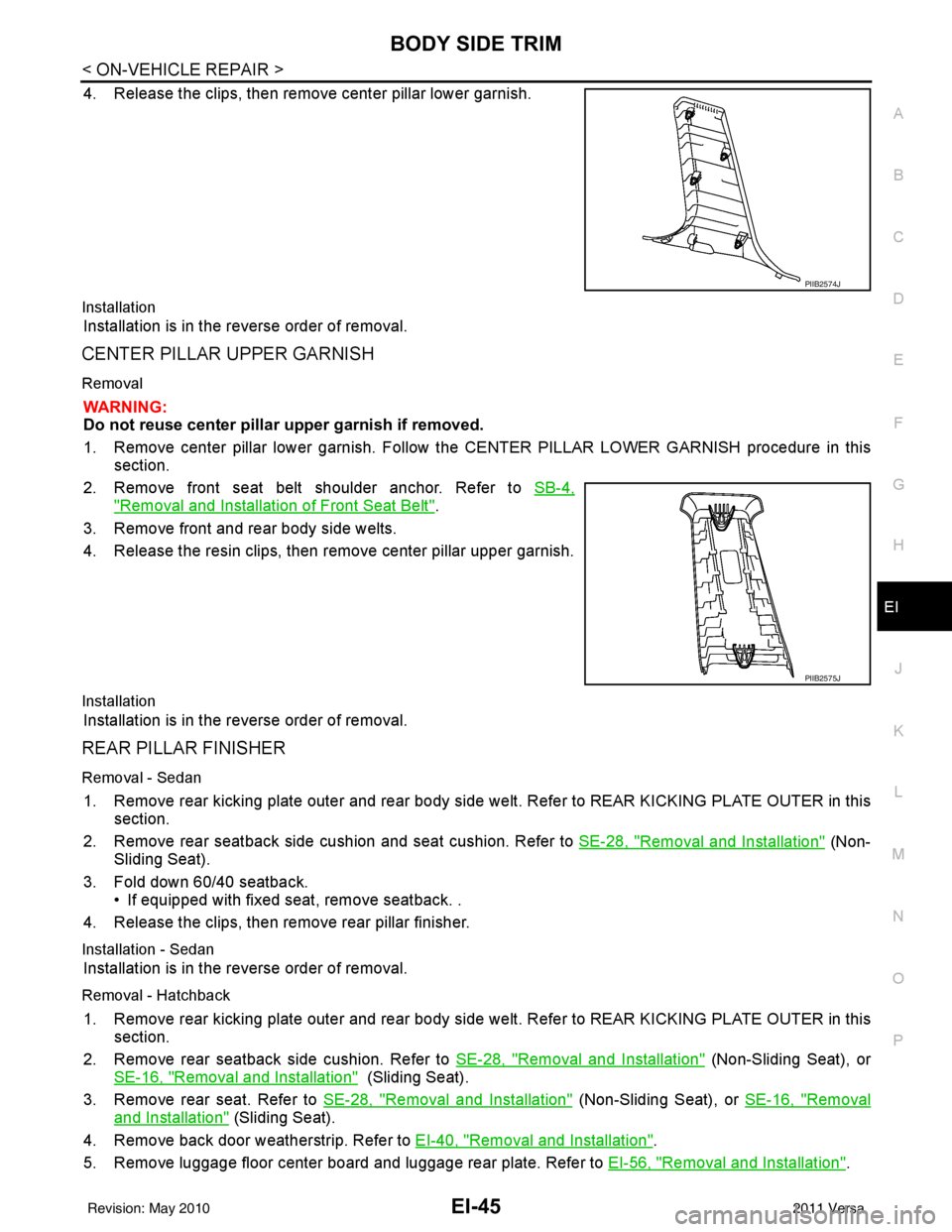
4. Release the clips, then remove center pillar lower garnish.
Installation
Installation is in the reverse order of removal.
CENTER PILLAR UPPER GARNISH
Removal
WARNING:
Do not reuse center pillar upper garnish if removed.
1. Remove center pillar lower garnish. Follow t he CENTER PILLAR LOWER GARNISH procedure in this
section.
2. Remove front seat belt shoulder anchor. Refer to SB-4,
"Removal and Installation of Front Seat Belt".
3. Remove front and rear body side welts.
4. Release the resin clips, then remove center pillar upper garnish.
Installation
Installation is in the reverse order of removal.
REAR PILLAR FINISHER
Removal - Sedan
1. Remove rear kicking plate outer and rear body side welt. Refer to REAR KICKING PLATE OUTER in this
section.
2. Remove rear seatback side cushion and seat cushion. Refer to SE-28, "
Removal and Installation" (Non-
Sliding Seat).
3. Fold down 60/40 seatback. • If equipped with fixed seat, remove seatback. .
4. Release the clips, then remove rear pillar finisher.
Installation - Sedan
Installation is in the reverse order of removal.
Removal - Hatchback
1. Remove rear kicking plate outer and rear body side welt. Refer to REAR KICKING PLATE OUTER in this
section.
2. Remove rear seatback side cushion. Refer to SE-28, "
Removal and Installation" (Non-Sliding Seat), or
SE-16, "
Removal and Installation" (Sliding Seat).
3. Remove rear seat. Refer to SE-28, "
Removal and Installation" (Non-Sliding Seat), or SE-16, "Removal
and Installation" (Sliding Seat).
4. Remove back door weatherstrip. Refer to EI-40, "
Removal and Installation".
5. Remove luggage floor center board and luggage rear plate. Refer to EI-56, "
Removal and Installation".
PIIB2574J
PIIB2575J
Revision: May 2010 2011 Versa
Page 2379 of 3787
FLOOR TRIMEI-49
< ON-VEHICLE REPAIR >
C
DE
F
G H
J
K L
M A
B
EI
N
O P
5. Remove front kicking plate inner RH/LH, center pillar lower garnish RH/LH, and rear kicking plate inner
RH/LH. Refer to EI-42, "
Removal and Installation".
6. Disconnect floor harness connector.
7. Remove diagnosis sensor unit. Refer to SRS-45
.
8. Remove key interlock cable. Refer to AT-219
.
9. Remove floor carpet hook.
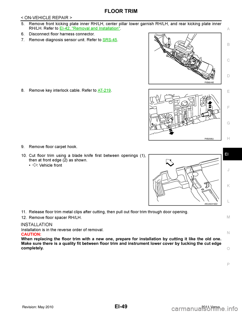
10. Cut floor trim using a blade knife first between openings (1), then at front edge (2) as shown.
• : Vehicle front
11. Release floor trim metal clips after cutting, then pull out floor trim through door opening.
12. Remove floor spacer RH/LH.
INSTALLATION
Installation is in the reverse order of removal.
CAUTION:
When replacing the floor trim with a new one, prep are for installation by cutting it like the old one.
Make sure there is a quality fit between floor trim and instrument lower cover by tucking the cut edge
completely.
PIIB6046E
PIIB2580J
AWJIA0419ZZ
Revision: May 2010 2011 Versa
Page 2382 of 3787
EI-52
< ON-VEHICLE REPAIR >
HEADLINING
Removal and Installation - Hatchback
INFOID:0000000005929576
REMOVAL
1. Disconnect the negative and positive battery termi nals, then wait at least three minutes.
2. Remove front seat assembly RH/LH. Refer to SE-12, "
Removal and Installation".
3. Remove rear seat cushion and rear seatback. Refer to SE-16, "
Removal and Installation" (60:40 Split Fold
Down Seat), or SE-28, "
Removal and Installation" (Fixed Back Seat).
4. Remove front seat belt shoulder anchor RH/LH. Refer to SB-4, "
Removal and Installation of Front Seat
Belt".
5. Remove center console body assembly. Refer to IP-11
.
6. Remove front pillar garnish RH/LH. Refer to EI-42, "
Removal and Installation".
7. Remove antenna feeder cable clip, then disconnect antenna feeder cable connector.
8. Remove front and rear kicking plate inner RH/LH, center pillar lower garnish, center pillar upper garnish, front and rear body side welt RH/LH. Refer to EI-42, "
Removal and Installation".
WARNING:
Do not reuse center pillar upper garnish if removed.
9. Remove back door weatherstrip. Refer to EI-40
.
10. Release the clips using a suitable tool, then remove the front and rear assist grips.
11. Remove the sunvisor caps and screws, then remove sunvisor RH/LH.
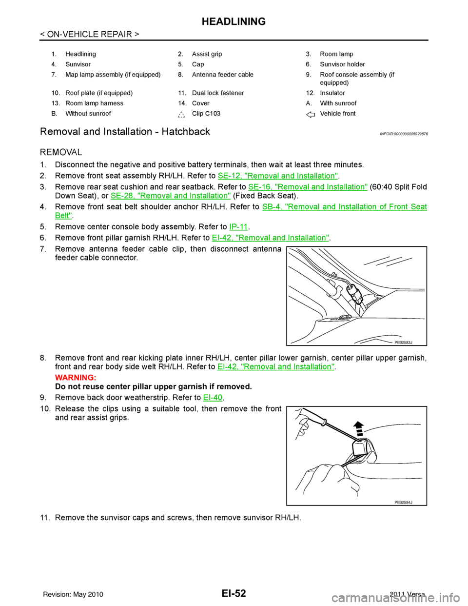
1. Headlining 2. Assist grip 3. Room lamp
4. Sunvisor 5. Cap 6. Sunvisor holder
7. Map lamp assembly (if equipped) 8. Antenna feeder cable 9. Roof console assembly (if
equipped)
10. Roof plate (if equipped) 11. Dual lock fastener 12. Insulator
13. Room lamp harness 14. Cover A. With sunroof
B. Without sunroof Clip C103Vehicle front
PIIB2583J
PIIB2584J
Revision: May 2010 2011 Versa
Page 2383 of 3787
HEADLININGEI-53
< ON-VEHICLE REPAIR >
C
DE
F
G H
J
K L
M A
B
EI
N
O P
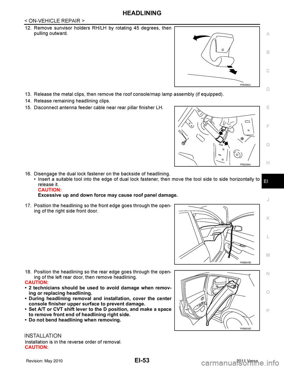
12. Remove sunvisor holders RH/LH by rotating 45 degrees, then pulling outward.
13. Release the metal clips, then remove the roof console/map lamp assembly (if equipped).
14. Release remaining headlining clips.
15. Disconnect antenna feeder cable near rear pillar finisher LH.
16. Disengage the dual lock fastener on the backside of headlining. • Insert a suitable tool into the edge of dual lock fa stener, then move the tool side to side horizontally to
release it.
CAUTION:
Excessive up and down force may cause roof panel damage.
17. Position the headlining so the front edge goes through the open- ing of the right side front door.
18. Position the headlining so the rear edge goes through the open- ing of the left rear door, then remove headlining.
CAUTION:
• 2 technicians should be used to avoid damage when remov-
ing or replacing headlining.
• During headlining removal and installation, cover the center
console finisher upper surface to prevent damage.
• Set A/T or CVT shift lever to the D position, and make a space
to remove front end of headlining right side.
• Do not bend headlining when removing.
INSTALLATION
Installation is in the reverse order of removal.
CAUTION:
PIIB3982J
PIIB2586J
PIIB6049E
PIIB6050E
Revision: May 2010 2011 Versa
Page 2385 of 3787
HEADLININGEI-55
< ON-VEHICLE REPAIR >
C
DE
F
G H
J
K L
M A
B
EI
N
O P
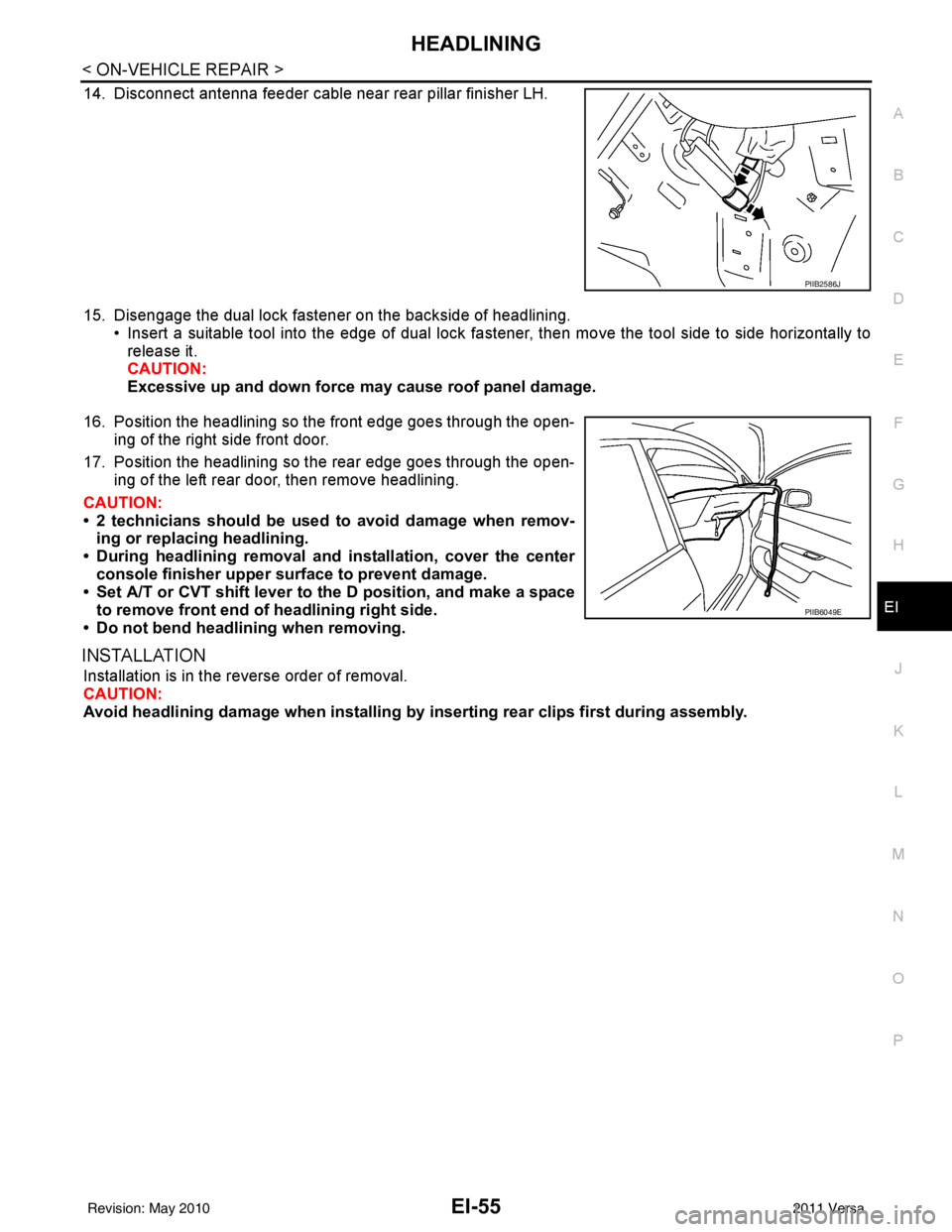
14. Disconnect antenna feeder cable near rear pillar finisher LH.
15. Disengage the dual lock fastener on the backside of headlining. • Insert a suitable tool into the edge of dual lock fa stener, then move the tool side to side horizontally to
release it.
CAUTION:
Excessive up and down force may cause roof panel damage.
16. Position the headlining so the front edge goes through the open- ing of the right side front door.
17. Position the headlining so the rear edge goes through the open- ing of the left rear door, then remove headlining.
CAUTION:
• 2 technicians should be used to avoid damage when remov-
ing or replacing headlining.
• During headlining removal and installation, cover the center
console finisher upper surface to prevent damage.
• Set A/T or CVT shift lever to the D position, and make a space
to remove front end of headlining right side.
• Do not bend headlining when removing.
INSTALLATION
Installation is in the reverse order of removal.
CAUTION:
Avoid headlining damage when installing by inserting rear clips first during assembly.
PIIB2586J
PIIB6049E
Revision: May 2010 2011 Versa
Page 2387 of 3787
LUGGAGE FLOOR TRIMEI-57
< ON-VEHICLE REPAIR >
C
DE
F
G H
J
K L
M A
B
EI
N
O P
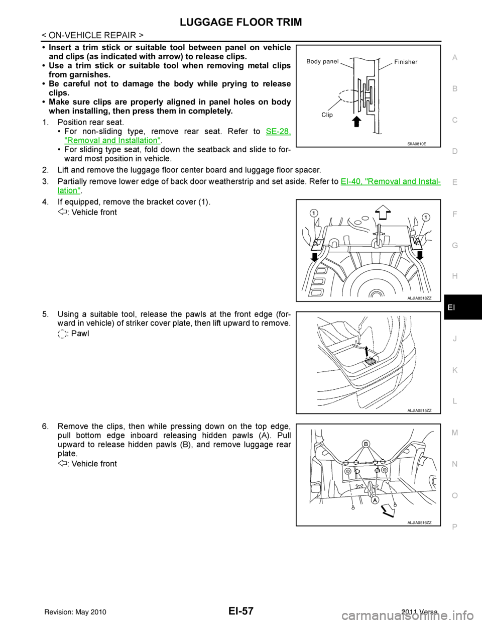
• Insert a trim stick or suitable tool between panel on vehicle and clips (as indicated with arrow) to release clips.
• Use a trim stick or suitable tool when removing metal clips
from garnishes.
• Be careful not to damage the body while prying to release clips.
• Make sure clips are properly al igned in panel holes on body
when installing, then press them in completely.
1. Position rear seat. • For non-sliding type, remove rear seat. Refer to SE-28,
"Removal and Installation".
• For sliding type seat, fold down the seatback and slide to for- ward most position in vehicle.
2. Lift and remove the luggage floor center board and luggage floor spacer.
3. Partially remove lower edge of back door weatherstrip and set aside. Refer to EI-40, "
Removal and Instal-
lation".
4. If equipped, remove the bracket cover (1). : Vehicle front
5. Using a suitable tool, release the pawls at the front edge (for- ward in vehicle) of striker cover plate, then lift upward to remove.
: Pawl
6. Remove the clips, then while pressing down on the top edge, pull bottom edge inboard releasing hidden pawls (A). Pull
upward to release hidden pawls (B), and remove luggage rear
plate.
: Vehicle front
SIIA0810E
ALJIA0518ZZ
ALJIA0515ZZ
ALJIA0516ZZ
Revision: May 2010 2011 Versa
Page 2673 of 3787
FL-6
< SERVICE INFORMATION >
FUEL LEVEL SENSOR UNIT, FUEL FILTER AND FUEL PUMP ASSEMBLY
FUEL LEVEL SENSOR UNIT, FUEL FILTER AND FUEL PUMP ASSEMBLY
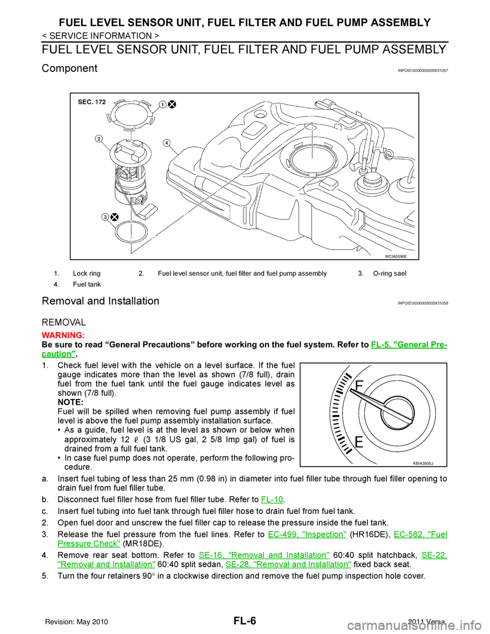
ComponentINFOID:0000000005931057
Removal and InstallationINFOID:0000000005931058
REMOVAL
WARNING:
Be sure to read “General Precautions” be fore working on the fuel system. Refer to FL-5, "
General Pre-
caution".
1. Check fuel level with the vehicle on a level surface. If the fuel gauge indicates more than the level as shown (7/8 full), drain
fuel from the fuel tank until the fuel gauge indicates level as
shown (7/8 full).
NOTE:
Fuel will be spilled when removing fuel pump assembly if fuel
level is above the fuel pump assembly installation surface.
• As a guide, fuel level is at the level as shown or below when
approximately 12 (3 1/8 US gal, 2 5/8 Imp gal) of fuel is
drained from a full fuel tank.
• In case fuel pump does not operate, perform the following pro- cedure.
a. Insert fuel tubing of less than 25 mm (0.98 in) in di ameter into fuel filler tube through fuel filler opening to
drain fuel from fuel filler tube.
b. Disconnect fuel filler hose from fuel filler tube. Refer to FL-10
.
c. Insert fuel tubing into fuel tank through f uel filler hose to drain fuel from fuel tank.
2. Open fuel door and unscrew the fuel filler cap to release the pressure inside the fuel tank.
3. Release the fuel pressure from the fuel lines. Refer to EC-499, "
Inspection" (HR16DE), EC-582, "Fuel
Pressure Check" (MR18DE).
4. Remove rear seat bottom. Refer to SE-16, "
Removal and Installation" 60:40 split hatchback, SE-22,
"Removal and Installation" 60:40 split sedan, SE-28, "Removal and Installation" fixed back seat.
5. Turn the four retainers 90 ° in a clockwise direction and remove the fuel pump inspection hole cover.
1. Lock ring 2. Fuel level sensor unit, fuel filter and fuel pump assembly 3. O-ring sael
4. Fuel tank
WCIA0590E
KBIA3505J
Revision: May 2010 2011 Versa
Page 2677 of 3787
FL-10
< SERVICE INFORMATION >
FUEL TANK
FUEL TANK
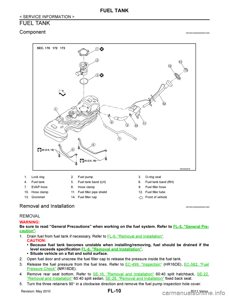
ComponentINFOID:0000000005931059
Removal and InstallationINFOID:0000000005931060
REMOVAL
WARNING:
Be sure to read “General Precautions” when working on the fuel system. Refer to FL-5, "
General Pre-
caution".
1. Drain fuel from fuel tank if necessary. Refer to FL-6, "
Removal and Installation".
CAUTION:
• Because fuel tank becomes unstable when installing/removing, fuel should be drained if the
level exceeds specification FL-6, "
Removal and Installation".
• Situate vehicle on a flat and solid surface.
2. Open fuel door and unscrew the fuel filler cap to release the pressure inside the fuel tank.
3. Release the fuel pressure from the fuel lines. Refer to EC-499, "
Inspection" (HR16DE), EC-582, "Fuel
Pressure Check" (MR18DE).
4. Remove rear seat bottom. Refer to SE-16, "
Removal and Installation" 60:40 split hatchback, SE-22,
"Removal and Installation" 60:40 split sedan, SE-28, "Removal and Installation" fixed back seat.
5. Turn the three retainers 90 ° in a clockwise direction and remove the fuel pump inspection hole cover.
1. Lock ring 2. Fuel pump 3. O-ring seal
4. Fuel tank 5. Fuel tank band (LH) 6. Fuel tank band (RH)
7. EVAP hose 8. Hose clamp 9. Fuel filler hose
10. Hose clamp 11. Fuel filler pipe shield 12. Fuel filler tube
13. Grommet 14. Fuel filler cap Front of vehicle
WCIA0591E
Revision: May 2010 2011 Versa