2011 NISSAN TIIDA door
[x] Cancel search: doorPage 763 of 3787

NATS (NISSAN ANTI-THEFT SYSTEM)BL-253
< SERVICE INFORMATION >
C
DE
F
G H
J
K L
M A
B
BL
N
O P
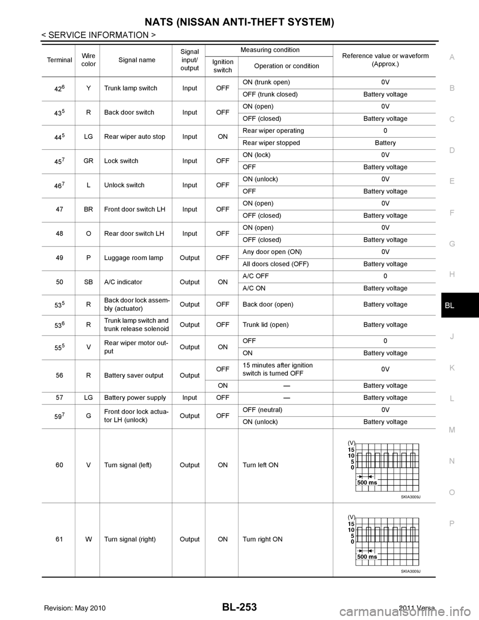
426Y Trunk lamp switch Input OFF ON (trunk open)
0V
OFF (trunk closed) Battery voltage
43
5R Back door switch Input OFF ON (open) 0V
OFF (closed)
Battery voltage
44
5LG Rear wiper auto stop Input ON Rear wiper operating 0
Rear wiper stopped
Battery
45
7GR Lock switch Input OFFON (lock)
0V
OFF Battery voltage
46
7L Unlock switch Input OFFON (unlock)
0V
OFF Battery voltage
47 BR Front door switch LH Input OFF ON (open)
0V
OFF (closed) Battery voltage
48 O Rear door switch LH Input OFF ON (open)
0V
OFF (closed) Battery voltage
49 P Luggage room lamp Output OFF Any door open (ON)
0V
All doors closed (OFF) Battery voltage
50 SB A/C indicator Output ONA/C OFF
0
A/C ON Battery voltage
53
5R Back door lock assem-
bly (actuator)
Output OFF Back door (open)
Battery voltage
53
6R Trunk lamp switch and
trunk release solenoid Output OFF Trunk lid (open)
Battery voltage
55
5V Rear wiper motor out-
put
Output ONOFF
0
ON Battery voltage
56 R Battery saver output Output OFF
15 minutes after ignition
switch is turned OFF 0V
ON — Battery voltage
57 LG Battery power supply Input OFF —Battery voltage
59
7G Front door lock actua-
tor LH (unlock)
Output OFFOFF (neutral)
0V
ON (unlock) Battery voltage
60 V Turn signal (left) Output ON Turn left ON
61 W Turn signal (right) Output ON Turn right ON
Te r m i n a l
Wire
color Signal name Signal
input/
output Measuring condition
Reference value or waveform
(Approx.)
Ignition
switch Operation or condition
SKIA3009J
SKIA3009J
Revision: May 2010
2011 Versa
Page 764 of 3787

BL-254
< SERVICE INFORMATION >
NATS (NISSAN ANTI-THEFT SYSTEM)
1: With Intelligent Key
2: Without Intelligent Key
3: Hatchback without Intelligent Key
4: Sedan without Intelligent Key
5: Hatchback
6: Sedan
7: With power door locks
8: With power windows
CONSULT-III FunctionINFOID:0000000005929437
CONSULT-III DIAGNOSTIC TEST MODE FUNCTION
*: When replace ECM, refer to BL-247, "ECM Re-communicating Function" .
NOTE:
• When any initialization is performed, all ID previ ously registered will be erased and all NATS mechanical
keys must be registered again.
• The engine cannot be started with an unregistered key. In this case, the system will show “DIFFERENCE OF
KEY” or “LOCK MODE” as a self-diagnos tic result on the CONSULT-III screen.
• In rare case, “CHAIN OF ECM-IMMU” might be stored as a self-diagnostic result during key registration pro-
cedure, even if the system is not malfunctioning.
NATS SELF DIAGNOSTIC RESULT ITEM CHART
63 BR Interior room lamp Output OFF Any door
switchON (open)
0V
OFF (closed) Battery voltage
65
7SB All door lock actuators
(lock) Output OFFOFF (neutral)
0V
ON (lock) Battery voltage
66
7G Front door lock actua-
tor RH, rear door lock
actuators LH/RH (un-
lock) Output OFFOFF (neutral)
0V
ON (unlock) Battery voltage
67 B Ground Input ON—0V
68
8L Power window power
supply (RAP)
Output —Ignition switch ON
Battery voltage
Within 45 seconds after igni-
tion switch OFF Battery voltage
More than 45 seconds after ig-
nition switch OFF 0V
When front door LH or RH is
open or power window timer
operates 0V
69
8P Battery power supply OutputOFF
— Battery voltage
70 Y Battery power supply Input OFF —Battery voltage
Te r m i n a l
Wire
color Signal name Signal
input/
output Measuring condition
Reference value or waveform
(Approx.)
Ignition
switch Operation or condition
Diagnostic mode
Description
C/U INITIALIZATION When replacing any of the following components, C/U initialization and re-registration of all
NATS mechanical keys are necessary.
[NATS mechanical key/ BCM/ ECM*]
SELF DIAGNOSTIC RESULT Detected items (screen terms) are as shown in the chart.
Refer to "NATS SELF-DIAGNOSTIC RESULTS ITEM CHART" .
Revision: May 2010
2011 Versa
Page 775 of 3787

BODY REPAIRBL-265
< SERVICE INFORMATION >
C
DE
F
G H
J
K L
M A
B
BL
N
O P
BODY REPAIR
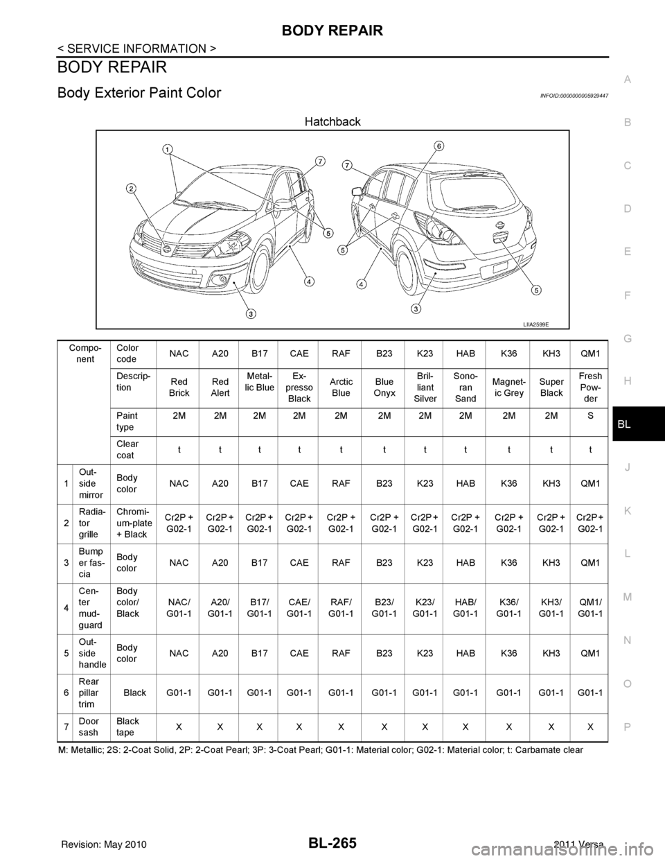
Body Exterior Paint ColorINFOID:0000000005929447
Hatchback
M: Metallic; 2S: 2-Coat Solid, 2P: 2-Coat Pearl; 3P: 3-Coat Pearl; G01-1: Material color; G02-1: Material color; t: Carbamate c lear
LIIA2599E
Compo-
nent Color
code
NAC A20 B17 CAE RAF B23 K23 HAB K36 KH3 QM1
Descrip-
tion Red
Brick Red
Alert Metal-
lic Blue Ex-
presso
Black Arctic
Blue Blue
Onyx Bril-
liant
Silver Sono-
ran
Sand Magnet-
ic Grey Super
Black Fresh
Pow-
der
Paint
type 2M 2M 2M 2M 2M 2M 2M 2M 2M 2M S
Clear
coat tttt t ttt t tt
1 Out-
side
mirror Body
color
NAC A20 B17 CAE RAF B23 K23 HAB K36 KH3 QM1
2 Radia-
tor
grille Chromi-
um-plate
+ Black
Cr2P +
G02-1 Cr2P +
G02-1 Cr2P +
G02-1 Cr2P +
G02-1 Cr2P +
G02-1 Cr2P +
G02-1 Cr2P +
G02-1 Cr2P +
G02-1 Cr2P +
G02-1 Cr2P +
G02-1 Cr2P +
G02-1
3 Bump
er fas-
cia Body
color
NAC A20 B17 CAE RAF B23 K23 HAB K36 KH3 QM1
4 Cen-
ter
mud-
guard Body
color/
Black
NAC/
G01-1 A20/
G01-1 B17/
G01-1 CAE/
G01-1 RAF/
G01-1 B23/
G01-1 K23/
G01-1 HAB/
G0 1-
1 K36/
G01
-1KH3/
G01-1 QM1/
G01-1
5 Out-
side
handle Body
color
NAC A20 B17 CAE RAF B23 K23 HAB K36 KH3 QM1
6 Rear
pillar
trim Black G01-1 G01-1 G01-1 G01-1 G01-1 G01-1 G01-1 G01-1 G01-1 G01-1 G01-1
7 Door
sash Black
tape
XXXX X XXX X XX
Revision: May 2010
2011 Versa
Page 776 of 3787

BL-266
< SERVICE INFORMATION >
BODY REPAIR
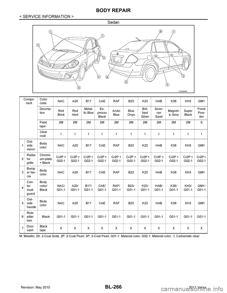
Sedan
M: Metallic; 2S: 2-Coat Solid, 2P: 2-Coat Pearl; 3P: 3-Coat Pearl; G01-1: Material color; G02-1: Material color ; t: Carbamate clear
LIIA2883E
Compo-
nent Color
code
NAC A20 B17 CAE RAF B23 K23 HAB K36 KH3 QM1
Descrip-
tion Red
Brick Red
Alert Metal-
lic Blue Ex-
presso
Black Arctic
Blue Blue
Onyx Bril-
liant
Silver Sono-
ran
Sand Magnet-
ic Grey Super
Black Fresh
Pow-
der
Paint
type 2M 2M 2M 2M 2M 2M 2M 2M 2M 2M S
Clear
coat tttt t ttt t tt
1 Out-
side
mirror Body
color
NAC A20 B17 CAE RAF B23 K23 HAB K36 KH3 QM1
2 Radia-
tor
grille Chromi-
um-plate
+ Black
Cr2P +
G02-1 Cr2P +
G02-1 Cr2P +
G02-1 Cr2P +
G02-1 Cr2P +
G02-1 Cr2P +
G02-1 Cr2P +
G02-1 Cr2P +
G02-1 Cr2P +
G02-1 Cr2P +
G02-1 Cr2P +
G02-1
3 Bump
er fas-
cia Body
color
NAC A20 B17 CAE RAF B23 K23 HAB K36 KH3 QM1
4 Cen-
ter
mud-
guard Body
color/
Black
NAC/
G01-1 A20/
G01-1 B17/
G01-1 CAE/
G01-1 RAF/
G01-1 B23/
G01-1 K23/
G01-1 HAB/
G0 1-1 K36/
G0 1-
1KH3/
G01-1 QM1/
G01-1
5 Out-
side
handle Body
color
NAC A20 B17 CAE RAF B23 K23 HAB K36 KH3 QM1
6 Rear
pillar
trim
Black G01-1 G01-1 G01-1 G01-1 G01-1 G01-1 G01-1 G01-1 G01-1 G01-1 G01-1
7 Door
sash Black
tape
XXXX X XXX X XX
Revision: May 2010
2011 Versa
Page 780 of 3787

BL-270
< SERVICE INFORMATION >
BODY REPAIR
6. 1st roof rail assembly
7. Front roof rail assembly
8. Sun roof assembly
9. Front roof rail assembly (if equipped with sunroof)
10. Roof side rail reinforcement (RH & LH)
11. Inner center pillar (RH & LH)
12. Hood assembly
13. Center pillar reinforcement (RH & LH)
14. Front pillar inner (RH & LH)
15. Front pillar upper reinforcement (RH & LH)
16. Front pillar lower reinforcement (RH & LH)
17. Fender (RH & LH)
18. Side body (RH & LH)
19. Side body assembly (RH & LH)
20. Outer sill (RH & LH)
21. Outer sill reinforcement (RH & LH)
22. Front door assembly (RH & LH)
23. Outer front door panel (RH & LH)
24. Outer rear door panel (RH & LH)
25. Rear door assembly (RH & LH)
26. Rear fender (RH & LH)
27. Rear fender assembly (RH & LH)
28. Rear fender corner (RH & LH)
29. Rear fender extension (RH & LH)
30. Rear combination lamp base (RH & LH)
31. Rear pillar inner reinforcement (RH & LH)
32. Rear wheel housing outer (RH & LH)
33. Rear wheel housing inner (RH & LH)
34. Rear spring base assembly (RH & LH)
35. Rear seatback hinge bracket (RH & LH)
36. Rear seatback catch bracket (RH & LH)
37. Rear pillar inner (RH & LH)
38. Rear roof rail reinforcement (RH & LH)
39. Rear roof rail brace (RH & LH)
40. Rear panel
41. Rear bumper fascia lower bracket
42. Rear bumper fascia upper bracket
43. Rear bumper fascia center bracket
44. Rear panel assembly
45. Back door assembly
Revision: May 20102011 Versa
Page 782 of 3787

BL-272
< SERVICE INFORMATION >
BODY REPAIR
7. Front roof rail assembly
8. Sun roof assembly
9. Front roof rail assembly (if equipped with sunroof)
10. Roof side rail reinforcement (RH & LH)
11. Inner center pillar (RH & LH)
12. Hood assembly
13. Center pillar reinforcement (RH & LH)
14. Front pillar inner (RH & LH)
15. Front pillar upper reinforcement (RH & LH)
16. Front pillar lower reinforcement (RH & LH)
17. Fender (RH & LH)
18. Side body (RH & LH)
19. Side body assembly (RH & LH)
20. Outer sill (RH & LH)
21. Outer sill reinforcement (RH & LH)
22. Front door assembly (RH & LH)
23. Outer front door panel (RH & LH)
24. Outer rear door panel (RH & LH)
25. Rear door assembly (RH & LH)
26. Rear fender (RH & LH)
27. Rear fender corner (RH & LH)
28. Rear combination lamp base (RH & LH)
29. Rear wheel housing front extension (RH & LH)
30. Rear wheel housing outer (RH & LH)
31. Rear pillar inner reinforcement (RH & LH)
32. Rear body side inner (RH & LH)
33. Rear wheel housing inner (RH & LH)
34. Rear panel assembly
35. Rear bumper fascia upper bracket
36. Rear bumper fascia center bracket
37. Trunk lid assembly
38. Parcel shelf side (RH & LH)
39. Parcel shelf assembly
40. Rear waist panel
41. Rear bumper fascia lower bracket
Corrosion ProtectionINFOID:0000000005929449
DESCRIPTION
To provide improved corrosion prevention, the following anti-corrosive measures have been implemented in
NISSAN production plants. When repairing or replacing body panels, it is necessary to use the same anti-cor-
rosive measures.
ANTI-CORROSIVE PRECOATED STEEL (GALVANNEALED STEEL)
Revision: May 2010 2011 Versa
Page 1091 of 3787
![NISSAN TIIDA 2011 Service Repair Manual CVT-36
< SERVICE INFORMATION >[RE0F08B]
TROUBLE DIAGNOSIS
CVT Electrical Parts Location
INFOID:0000000005928751
1. O/D OFF indicator lamp 2. Shift position indicator3. Accelerator pedal position senso NISSAN TIIDA 2011 Service Repair Manual CVT-36
< SERVICE INFORMATION >[RE0F08B]
TROUBLE DIAGNOSIS
CVT Electrical Parts Location
INFOID:0000000005928751
1. O/D OFF indicator lamp 2. Shift position indicator3. Accelerator pedal position senso](/manual-img/5/57396/w960_57396-1090.png)
CVT-36
< SERVICE INFORMATION >[RE0F08B]
TROUBLE DIAGNOSIS
CVT Electrical Parts Location
INFOID:0000000005928751
1. O/D OFF indicator lamp 2. Shift position indicator3. Accelerator pedal position sensor
4. CVT unit harness connector 5. Fuel door release 6. TCM
7. Overdrive control switch
BCIA0033E
Revision: May 2010 2011 Versa
Page 1240 of 3787

DI-1
ELECTRICAL
C
DE
F
G H
I
J
L
M
SECTION DI
A
B
DI
N
O P
CONTENTS
DRIVER INFORMATION SYSTEM
SERVICE INFORMATION .. ..........................2
PRECAUTION ................................................ .....2
Precaution for Supplemental Restraint System
(SRS) "AIR BAG" and "SEAT BELT PRE-TEN-
SIONER" ............................................................. ......
2
Precaution Necessary for Steering Wheel Rota-
tion After Battery Disconnect ............................... ......
2
COMBINATION METERS ...................................4
Component Parts and Harness Connector Loca-
tion ...................................................................... ......
4
System Description ...................................................4
Arrangement of Combination Meter ..........................6
Internal Circuit ...........................................................7
Wiring Diagram - METER - .......................................8
Combination Meter Harness Connector Terminal
Layout .....................................................................
10
Terminal and Reference Value for Combination
Meter .......................................................................
10
Self-Diagnosis Mode of Combination Meter ........ ....11
CONSULT-III Function (METER/M&A) ............... ....13
Trouble Diagnosis ...................................................14
Symptom Chart .......................................................15
Power Supply and Ground Circuit Inspection .........15
Vehicle Speed Signal Inspection .............................16
Engine Speed Signal Inspection .............................17
Fuel Level Sensor Signal Inspection .......................17
Fuel Gauge Fluctuates, Indicates Wrong Value, or
Varies ......................................................................
19
Fuel Gauge Does Not Move to Full-position ...........19
DTC [U1000] CAN Communication Circuit ......... ....19
Electrical Component Inspection .............................20
Removal and Installation .........................................20
WARNING LAMPS ......................................... ....21
Schematic ........................................................... ....21
Wiring Diagram - WARN - ................................... ....22
Oil Pressure Warning Lamp Stays Off (Ignition
Switch ON) .......................................................... ....
30
Oil Pressure Warning Lamp Does Not Turn Off
(Oil Pressure Is Normal) ...................................... ....
32
Component Inspection .............................................32
A/T INDICATOR ................................................34
System Description ..................................................34
Wiring Diagram - AT/IND - .......................................35
A/T Indicator Does Not Illuminate ............................36
CVT INDICATOR ...............................................38
System Description ..................................................38
Schematic ................................................................38
Wiring Diagram - CVTIND - .....................................39
CVT Indicator Does Not Illuminate ..........................41
WARNING CHIME .............................................43
Component Parts and Harness Connector Loca-
tion ....................................................................... ....
43
System Description ..................................................43
Wiring Diagram - CHIME - .......................................46
Terminal and Reference Value for BCM ..................47
CONSULT-III Function (B CM) .................................47
Trouble Diagnosis ................................................ ....48
Combination Meter Buzzer Circuit Inspection .........49
Front Door Switch LH Signal Inspection .............. ....50
Key Switch Signal Inspection (Without Intelligent
Key) ..................................................................... ....
51
Key Switch and Ignition Knob Switch Signal In-
spection (With Intelligent Key, When Mechanical
Key Is Used) ........................................................ ....
52
Lighting Switch Signal Inspection ............................54
Parking Brake Switch Signal Inspection ..................54
Electrical Component Inspection .............................55
Revision: May 2010 2011 Versa