Page 3216 of 3787

CHASSIS AND BODY MAINTENANCEMA-45
< SERVICE INFORMATION >
C
DE
F
G H
I
J
K
M A
B
MA
N
O P
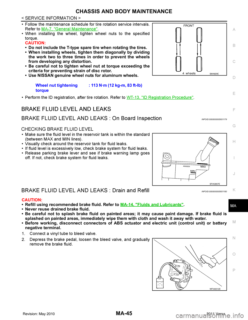
• Follow the maintenance schedule for tire rotation service intervals. Refer to MA-7, "
General Maintenance".
• When installing the wheel, tighten wheel nuts to the specified
torque.
CAUTION:
• Do not include the T-type spare tire when rotating the tires.
• When installing wheels, tighte n them diagonally by dividing
the work two to three times in order to prevent the wheels
from developing any distortion.
• Be careful not to tighten wh eel nut at torque exceeding the
criteria for preventing strain of disc rotor.
• Use NISSAN genuine wheel nuts for aluminum wheels.
• Perform the ID registration, after tire rotation. Refer to WT-13, "
ID Registration Procedure".
BRAKE FLUID LEVEL AND LEAKS
BRAKE FLUID LEVEL AND LEAKS : On Board InspectionINFOID:0000000005931179
CHECKING BRAKE FLUID LEVEL
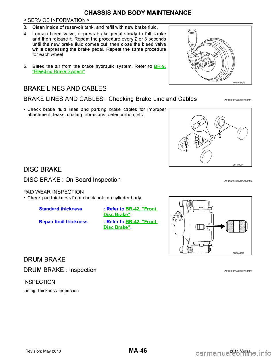
• Make sure the fluid level in the reservoir tank is within the standard
(between MAX and MIN lines).
• Visually check around the reservoir tank for fluid leaks.
• If fluid level is excessively low, check brake system for fluid leaks.
• Release parking brake lever and see if brake warning lamp goes off. If not, check brake system for fluid leaks.
BRAKE FLUID LEVEL AND LEAKS : Drain and RefillINFOID:0000000005931180
CAUTION:
• Refill using recommended brake fluid. Refer to MA-14, "
Fluids and Lubricants".
• Never reuse drained brake fluid.
• Be careful not to splash brake fluid on painted areas; it may cause paint damage. If brake fluid is
splashed on painted areas, immediately wipe th em with cloth and wash it away with water.
• Before working, disconnect connect ors of ABS actuator and electric unit (control unit) or battery
negative terminal.
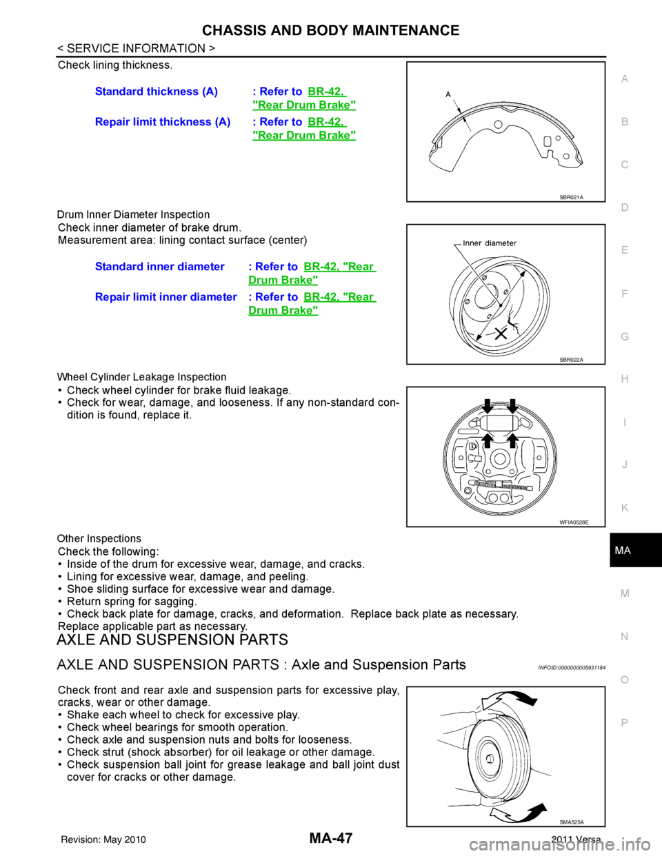
1. Connect a vinyl tube to bleed valve.
2. Depress the brake pedal, loosen the bleed valve, and gradually remove the brake fluid.Wheel nut tightening
torque
: 113 N·m (12 kg-m, 83 ft-lb)
SMA829C
SFIA3067E
WFIA0512E
Revision: May 2010
2011 Versa
Page 3217 of 3787

MA-46
< SERVICE INFORMATION >
CHASSIS AND BODY MAINTENANCE
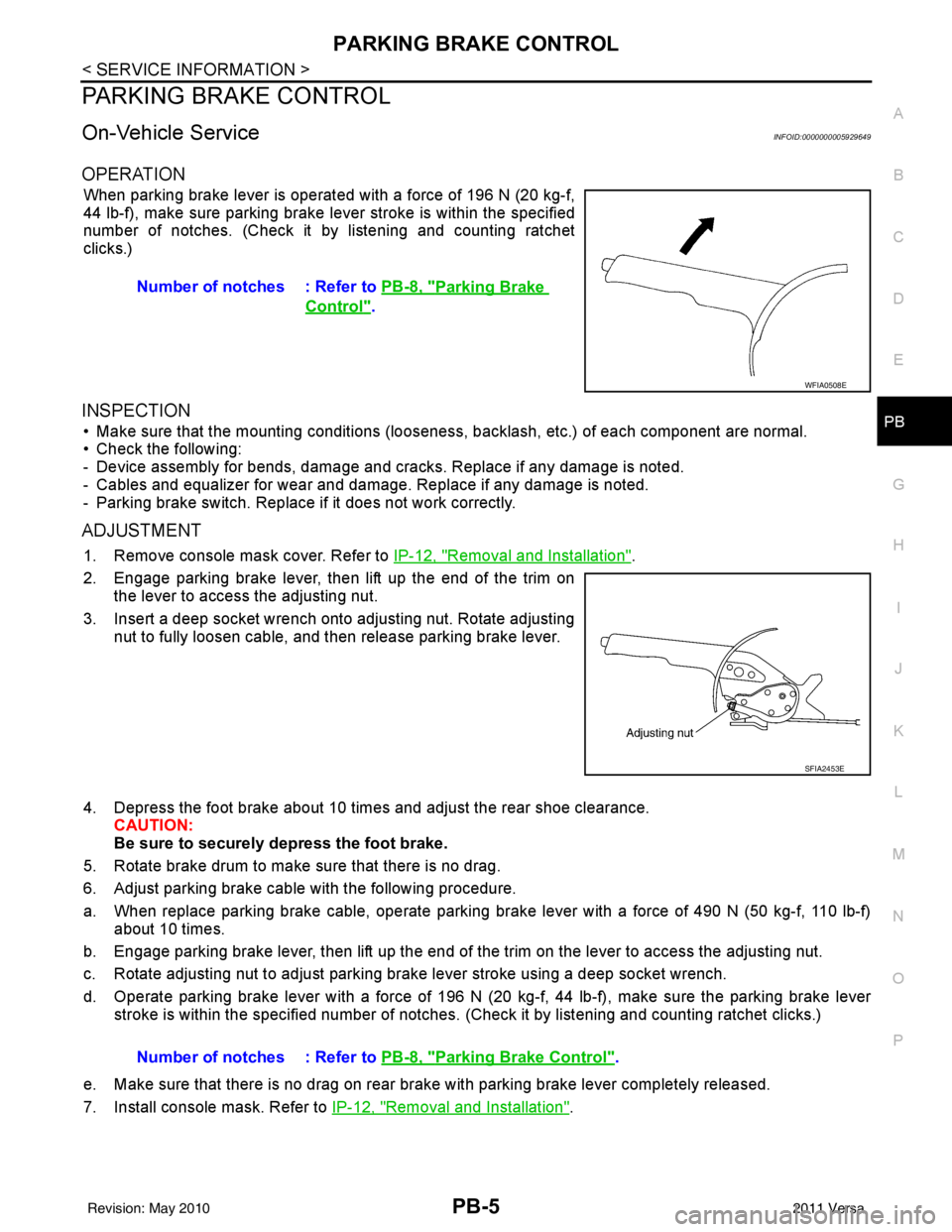
3. Clean inside of reservoir tank, and refill with new brake fluid.
4. Loosen bleed valve, depress brake pedal slowly to full strokeand then release it. Repeat the procedure every 2 or 3 seconds
until the new brake fluid comes out, then close the bleed valve
while depressing the brake pedal. Repeat the same procedure
for each wheel.
5. Bleed the air from the brake hydraulic system. Refer to BR-9,
"Bleeding Brake System" .
BRAKE LINES AND CABLES
BRAKE LINES AND CABLES : Ch ecking Brake Line and CablesINFOID:0000000005931181
• Check brake fluid lines and parking brake cables for improper
attachment, leaks, chafing, abrasions, deterioration, etc.
DISC BRAKE
DISC BRAKE : On Board InspectionINFOID:0000000005931182
PAD WEAR INSPECTION
• Check pad thickness from check hole on cylinder body.
DRUM BRAKE
DRUM BRAKE : InspectionINFOID:0000000005931183
INSPECTION
Lining Thickness Inspection
WFIA0513E
SBR389C
Standard thickness : Refer to BR-42, "Front
Disc Brake".
Repair limit thickness : Refer to BR-42, "
Front
Disc Brake".
BRA0010D
Revision: May 2010 2011 Versa
Page 3218 of 3787

CHASSIS AND BODY MAINTENANCEMA-47
< SERVICE INFORMATION >
C
DE
F
G H
I
J
K
M A
B
MA
N
O P
Check lining thickness.
Drum Inner Diameter Inspection
Check inner diameter of brake drum.
Measurement area: lining contact surface (center)
Wheel Cylinder Leakage Inspection
• Check wheel cylinder for brake fluid leakage.
• Check for wear, damage, and looseness. If any non-standard con- dition is found, replace it.
Other Inspections
Check the following:
• Inside of the drum for excessive wear, damage, and cracks.
• Lining for excessive wear, damage, and peeling.
• Shoe sliding surface for excessive wear and damage.
• Return spring for sagging.
• Check back plate for damage, cracks, and deformation. Replace back plate as necessary.
Replace applicable part as necessary.
AXLE AND SUSPENSION PARTS
AXLE AND SUSPENSION PARTS : Axle and Suspension PartsINFOID:0000000005931184
Check front and rear axle and suspension parts for excessive play,
cracks, wear or other damage.
• Shake each wheel to check for excessive play.
• Check wheel bearings for smooth operation.
• Check axle and suspension nuts and bolts for looseness.
• Check strut (shock absorber) for oil leakage or other damage.
• Check suspension ball joint for grease leakage and ball joint dust
cover for cracks or other damage. Standard thickness (A) : Refer to
BR-42,
"Rear Drum Brake"
Repair limit thickness (A) : Refer toBR-42,
"Rear Drum Brake"
SBR021A
Standard inner diameter : Refer toBR-42, "Rear
Drum Brake"
Repair limit inner diameter : Refer toBR-42, "Rear
Drum Brake"
SBR022A
WFIA0528E
SMA525A
Revision: May 2010 2011 Versa
Page 3225 of 3787
![NISSAN LATIO 2011 Service Repair Manual MT-4
< SERVICE INFORMATION >[RS5F91R]
PRECAUTIONS
5. When the repair work is completed, return the ignition switch to the
″LOCK ″ position before connecting
the battery cables. (At this time, the NISSAN LATIO 2011 Service Repair Manual MT-4
< SERVICE INFORMATION >[RS5F91R]
PRECAUTIONS
5. When the repair work is completed, return the ignition switch to the
″LOCK ″ position before connecting
the battery cables. (At this time, the](/manual-img/5/57357/w960_57357-3224.png)
MT-4
< SERVICE INFORMATION >[RS5F91R]
PRECAUTIONS
5. When the repair work is completed, return the ignition switch to the
″LOCK ″ position before connecting
the battery cables. (At this time, the steering lock mechanism will engage.)
6. Perform a self-diagnosis check of a ll control units using CONSULT-III.
Precaution for Procedure without Cowl Top CoverINFOID:0000000005929655
When performing the procedure after removing cowl top cover, cover
the lower end of windshield with urethane, etc.
Service Notice or PrecautionINFOID:0000000005929656
•Use recommended brake fluid when adding flui d to the clutch reservoir tank. Refer to MA-14.
• Never reuse fluid drained from clutch system.
• Be careful not to splash brake fluid on painted areas.
• Use new brake fluid to clean or wash all part s of master cylinder and operating cylinder.
• Never use mineral oils such as gasoline or kerosene. It will ruin the rubber parts of the hydraulic sys-
tem.
• If transaxle assembly is removed from the vehicle , always replace CSC (Concentric slave cylinder).
Return CSC to original position to remove transaxle assembly. Dust on clutch disc sliding parts may
damage CSC seal and may cause clutch fluid leakage.
• Do not disassemble clutch master cylinder and CSC.
WARNING:
After cleaning clutch disc, clean it with a dust collector. Do not use compressed air.
PIIB3706J
Revision: May 2010 2011 Versa
Page 3383 of 3787
BLOWER FAN RESISTORMTC-67
< SERVICE INFORMATION >
C
DE
F
G H
I
K L
M A
B
MTC
N
O P
BLOWER FAN RESISTOR
Removal and InstallationINFOID:0000000005930866
REMOVAL
1. Remove the instrument lower finisher. Refer to IP-11.
2. Remove the console side cover. Refer to IP-11
.
3. Remove the brake pedal assembly. Refer to BR-6
.
4. Disconnect the blower fan resistor connector.
5. Remove the blower fan resistor screws (A), then remove the blower fan resistor (1).
INSTALLATION
Installation is in the reverse order of removal.
SJIA0656E
Revision: May 2010 2011 Versa
Page 3413 of 3787

PB-1
BRAKES
C
DE
G H
I
J
K L
M
SECTION PB
A
B
PB
N
O P
CONTENTS
PARKING BRAKE SYSTEM
SERVICE INFORMATION .. ..........................2
PRECAUTIONS .............................................. .....2
Precaution for Supplemental Restraint System
(SRS) "AIR BAG" and "SEAT BELT PRE-TEN-
SIONER" ............................................................. ......
2
Precaution Necessary for Steering Wheel Rota-
tion After Battery Disconnect ............................... ......
2
PREPARATION ...................................................4
Commercial Service Tool .................................... .....4
PARKING BRAKE CONTROL ...........................5
On-Vehicle Service ...................................................5
Component ...............................................................6
Removal and Installation ..........................................6
SERVICE DATA AND SPECIFICATIONS
(SDS) ..................................................................
8
Parking Brake Control ..............................................8
Revision: May 2010 2011 Versa
Page 3417 of 3787

PARKING BRAKE CONTROLPB-5
< SERVICE INFORMATION >
C
DE
G H
I
J
K L
M A
B
PB
N
O P
PARKING BRAKE CONTROL
On-Vehicle ServiceINFOID:0000000005929649
OPERATION
When parking brake lever is operated with a force of 196 N (20 kg-f,
44 lb-f), make sure parking brake le ver stroke is within the specified
number of notches. (Check it by listening and counting ratchet
clicks.)
INSPECTION
• Make sure that the mounting conditions (looseness, backlash, etc.) of each component are normal.
• Check the following:
- Device assembly for bends, damage and cracks. Replace if any damage is noted.
- Cables and equalizer for wear and damage. Replace if any damage is noted.
- Parking brake switch. Replace if it does not work correctly.
ADJUSTMENT
1. Remove console mask cover. Refer to IP-12, "Removal and Installation".
2. Engage parking brake lever, then lift up the end of the trim on the lever to access the adjusting nut.
3. Insert a deep socket wrench onto adjusting nut. Rotate adjusting nut to fully loosen cable, and then release parking brake lever.
4. Depress the foot brake about 10 ti mes and adjust the rear shoe clearance.
CAUTION:
Be sure to securely depress the foot brake.
5. Rotate brake drum to make sure that there is no drag.
6. Adjust parking brake cable with the following procedure.
a. When replace parking brake cable, operate parking br ake lever with a force of 490 N (50 kg-f, 110 lb-f)
about 10 times.
b. Engage parking brake lever, then lift up the end of the trim on the lever to access the adjusting nut.
c. Rotate adjusting nut to adjust parking brake lever stroke using a deep socket wrench.
d. Operate parking brake lever with a force of 196 N (20 kg-f, 44 lb-f), make sure the parking brake lever
stroke is within the specified number of notches. (Check it by listening and counting ratchet clicks.)
e. Make sure that there is no drag on rear brake with parking brake lever completely released.
7. Install console mask. Refer to IP-12, "
Removal and Installation".
Number of notches : Refer to
PB-8, "
Parking Brake
Control".
WFIA0508E
SFIA2453E
Number of notches : Refer to PB-8, "Parking Brake Control".
Revision: May 2010 2011 Versa
Page 3418 of 3787
PB-6
< SERVICE INFORMATION >
PARKING BRAKE CONTROL
Component
INFOID:0000000005929650
Removal and InstallationINFOID:0000000005929651
REMOVAL
1. Remove center console assembly. Refer to IP-12, "Removal and Installation".
2. Disconnect parking brake switch connector.
3. Loosen adjusting nut.
4. Remove equalizer from rear cable terminal ends.
5. Take off rear cable clip, and unplug rear cable outward. NOTE:
Close opening to take off clip.
6. Remove device assembly nuts, and remove device assembly.
7. Remove rear brake shoe and remove rear cable from the operating lever. Refer to BR-36, "
Removal and
Installation of Drum Brake Assembly".
8. Remove the exhaust center tube and heat plate. Refer to EX-10, "
Removal and Installation".
9. Remove rear cable bolt and nut, and then remove rear cable.
1. Device assembly 2. Adjusting nut3. Parking brake switch
4. Front cable 5. Equalizer6. LH rear cable
7. RH rear cable
AWFIA0531GB
WFIA0510E
Revision: May 2010 2011 Versa