Page 8 of 3787
2011
QUICK REFERENCE INDEX: VERSA
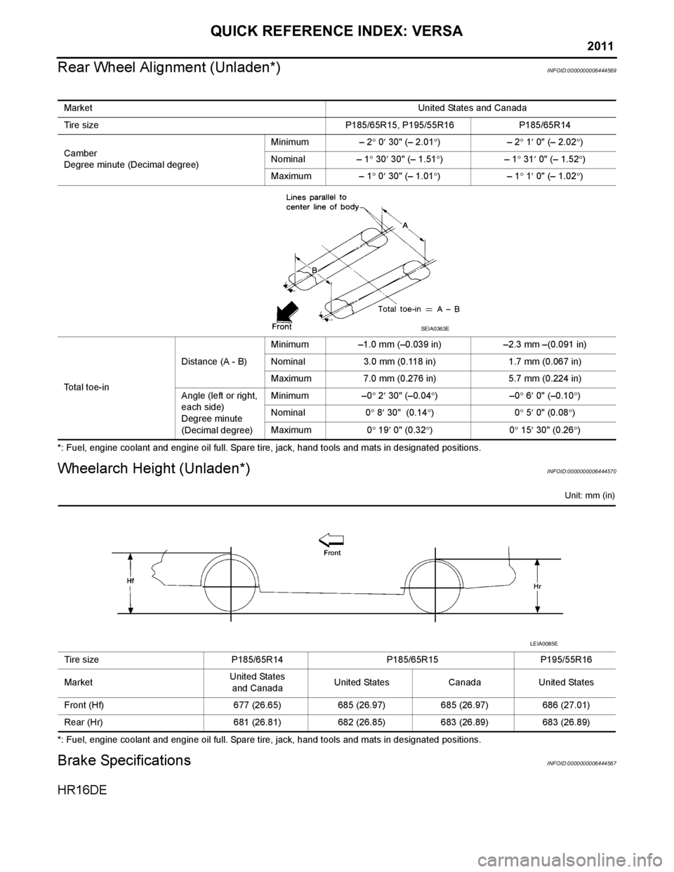
Rear Wheel Alignment (Unladen*)
INFOID:0000000006444569
*: Fuel, engine coolant and engine oil full. Spare tire, jack, hand tools and mats in designated positions.
Wheelarch Height (Unladen*)INFOID:0000000006444570
Unit: mm (in)
*: Fuel, engine coolant and engine oil full. Spare tire, jack, hand tools and mats in designated positions.
Brake SpecificationsINFOID:0000000006444567
HR16DE
Market United States and Canada
Tire size P185/65R15, P195/55R16P185/65R14
Camber
Degree minute (Decimal degree) Minimum
– 2° 0 ′ 30" (– 2.01 °)– 2° 1 ′ 0" (– 2.02 °)
Nominal – 1° 30 ′ 30" (– 1.51 °)– 1° 31 ′ 0" (– 1.52 °)
Maximum – 1° 0 ′ 30" (– 1.01 °)– 1° 1 ′ 0" (– 1.02 °)
Total toe-in Distance (A - B)
Minimum
–1.0 mm (–0.039 in) –2.3 mm –(0.091 in)
Nominal 3.0 mm (0.118 in) 1.7 mm (0.067 in)
Maximum 7.0 mm (0.276 in) 5.7 mm (0.224 in)
Angle (left or right,
each side)
Degree minute
(Decimal degree) Minimum
–0° 2 ′ 30" (–0.04 °)– 0° 6 ′ 0" (–0.10 °)
Nominal 0° 8 ′ 30" (0.14 °)0 ° 5 ′ 0" (0.08 °)
Maximum 0° 19 ′ 0" (0.32 °)0 ° 15 ′ 30" (0.26 °)
SEIA0363E
Tire size P185/65R14P185/65R15P195/55R16
Market United States
and Canada United States
CanadaUnited States
Front (Hf) 677 (26.65)685 (26.97)685 (26.97)686 (27.01)
Rear (Hr) 681 (26.81)682 (26.85)683 (26.89)683 (26.89)
LEIA0085E
Page 10 of 3787
2011
QUICK REFERENCE INDEX: VERSA
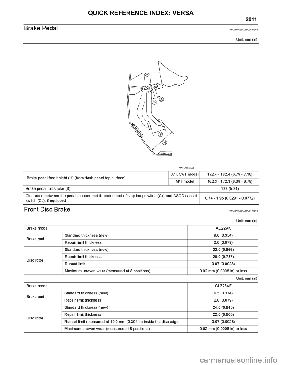
Brake Pedal
INFOID:0000000006444568
Unit: mm (in)
Front Disc BrakeINFOID:0000000006444565
Unit: mm (in)
Unit: mm (in)
Brake pedal free height (H) (from dash panel top surface) A/T, CVT model 172.4 - 182.4 (6.79 - 7.18)
M/T model 162.3 - 172.3 (6.39 - 6.78)
Brake pedal full stroke (S) 133 (5.24)
Clearance between the pedal stopper and threaded end of stop lamp switch (C
1) and ASCD cancel
switch (C
2), if equipped 0.74 - 1.96 (0.0291 - 0.0772)
AWFIA0557ZZ
Brake model
AD22VK
Brake pad Standard thickness (new) 9.0 (0.354)
Repair limit thickness 2.0 (0.079)
Disc rotor Standard thickness (new)
22.0 (0.866)
Repair limit thickness 20.0 (0.787)
Runout limit 0.07 (0.0028)
Maximum uneven wear (measured at 8 positions) 0.02 mm (0.0008 in) or less
Brake model CLZ25VF
Brake pad Standard thickness (new)
9.5 (0.374)
Repair limit thickness 2.0 (0.079)
Disc rotor Standard thickness (new)
24.0 (0.945)
Repair limit thickness 22.0 (0.866)
Runout limit (measured at 10.0 mm (0.394 in) inside the disc edge 0.07 (0.0028)
Maximum uneven wear (measured at 8 positions) 0.02 mm (0.0008 in) or less
Page 371 of 3787
AT-354
< SERVICE INFORMATION >
ASSEMBLY
b. Install needle bearing on bearing retainer.CAUTION:
Be careful to direction of needle bearing.
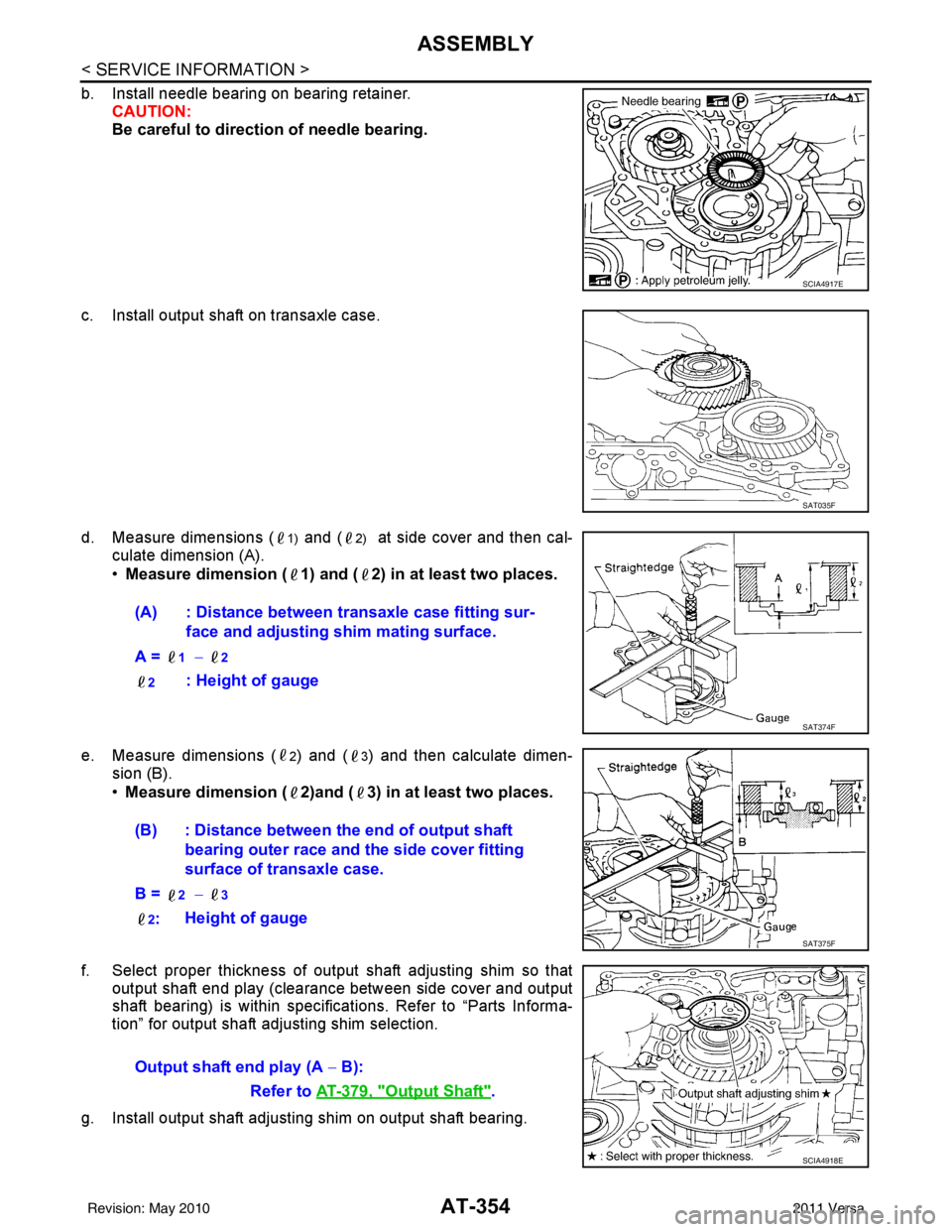
c. Install output shaft on transaxle case.
d. Measure dimensions (
1) and (2) at side cover and then cal-
culate dimension (A).
• Measure dimension ( 1) and ( 2) in at least two places.
e. Measure dimensions (
2) and (3) and then calculate dimen-
sion (B).
• Measure dimension ( 2)and ( 3) in at least two places.
f. Select proper thickness of output shaft adjusting shim so that output shaft end play (clearance between side cover and output
shaft bearing) is within specifications. Refer to “Parts Informa-
tion” for output shaft adjusting shim selection.
g. Install output shaft adjusting shim on output shaft bearing.
SCIA4917E
SAT035F
(A) : Distance between transaxle case fitting sur- face and adjusting shim mating surface.
A =
1 − 2
2
: Height of gauge
SAT374F
(B) : Distance between the end of output shaft bearing outer race and the side cover fitting
surface of transaxle case.
B =
2 − 3
2
: Height of gauge
SAT375F
Output shaft end play (A
− B):
Refer to AT-379, "
Output Shaft".
SCIA4918E
Revision: May 2010 2011 Versa
Page 383 of 3787
AT-366
< SERVICE INFORMATION >
ASSEMBLY
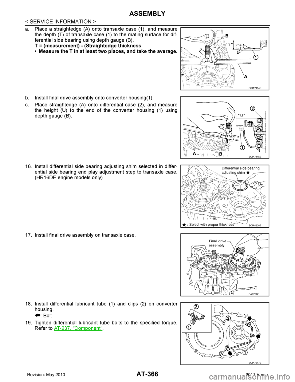
a. Place a straightedge (A) onto transaxle case (1), and measurethe depth (T) of transaxle case (1) to the mating surface for dif-
ferential side bearing using depth gauge (B).
T = (measurement) - (Straightedge thickness
•Measure the T in at least two places, and take the average.
b. Install final drive assembly onto converter housing(1).
c. Place straightedge (A) onto differential case (2), and measure the height (U) to the end of the converter housing (1) using
depth gauge (B).
16. Install differential side bearing adjusting shim selected in differ- ential side bearing end play adjustment step to transaxle case.
(HR16DE engine models only)
17. Install final drive assembly on transaxle case.
18. Install differential lubricant tube (1) and clips (2) on converter housing.
: Bolt
19. Tighten differential lubricant tube bolts to the specified torque. Refer to AT-237, "
Component".
SCIA7114E
SCIA7115E
SCIA4938E
SAT228F
SCIA7817E
Revision: May 2010 2011 Versa
Page 523 of 3787
HOODBL-13
< SERVICE INFORMATION >
C
DE
F
G H
J
K L
M A
B
BL
N
O P
HOOD
Fitting AdjustmentINFOID:0000000005929276
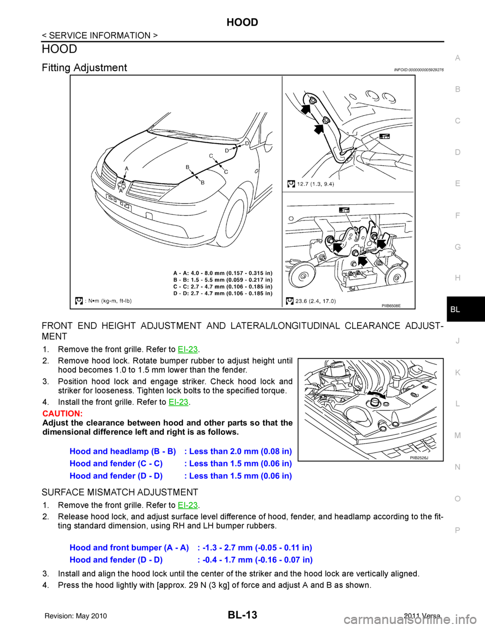
FRONT END HEIGHT ADJUSTMENT AND LA TERAL/LONGITUDINAL CLEARANCE ADJUST-
MENT
1. Remove the front grille. Refer to EI-23.
2. Remove hood lock. Rotate bumper rubber to adjust height until hood becomes 1.0 to 1.5 mm lower than the fender.
3. Position hood lock and engage striker. Check hood lock and striker for looseness. Tighten lock bolts to the specified torque.
4. Install the front grille. Refer to EI-23
.
CAUTION:
Adjust the clearance between hood and other parts so that the
dimensional difference left and right is as follows.
SURFACE MISMATCH ADJUSTMENT
1. Remove the front grille. Refer to EI-23.
2. Release hood lock, and adjust surface level difference of hood, fender, and headlamp according to the fit- ting standard dimension, using RH and LH bumper rubbers.
3. Install and align the hood lock until the center of the striker and the hood lock are vertically aligned.
4. Press the hood lightly with [approx. 29 N (3 kg] of force and adjust A and B as shown.
PIIB6508E
Hood and headlamp (B - B) : Less than 2.0 mm (0.08 in)
Hood and fender (C - C) : Less than 1.5 mm (0.06 in)
Hood and fender (D - D) : Less than 1.5 mm (0.06 in)PIIB2526J
Hood and front bumper (A - A) : -1.3 - 2.7 mm (-0.05 - 0.11 in)
Hood and fender (D - D) : -0.4 - 1.7 mm (-0.16 - 0.07 in)
Revision: May 2010 2011 Versa
Page 670 of 3787
BL-160
< SERVICE INFORMATION >
DOOR
DOOR
Fitting AdjustmentINFOID:0000000005929373
FRONT DOOR
Longitudinal Clearance at Front End
Access from inside the fender to loosen the hinge bolts. Raise the front door at rear end to adjust.
Surface Height Adjustment
Loosen the front door bolts, and adjust the surface height difference of fender and front door according to the
fitting standard dimension.
Striker Adjustment
1. Front fender2. Front door outer3. Rear door outer
4. Rear fender 5. Front door weatherstrip 6. Front door sash
7. Rear door weatherstrip 8. Rear door sash
PIIB6516E
Revision: May 2010 2011 Versa
Page 671 of 3787
DOOR
BL-161
< SERVICE INFORMATION >
C
D E
F
G H
J
K L
M A
B
BL
N
O P
REAR DOOR
Longitudinal Clearance and Surface Height Adjustment at Front End
1. Remove the center pillar upper and lower garnishes. Refer to EI-41.
2. Access from inside the vehicle to loosen the hinge nuts. Open the rear door, and raise the rear door at
rear end to adjust.
Surface Height Adjustment
Loosen the front door striker bolts and rear door hinge nu ts, and adjust the surface height difference of front
and rear doors according to the fitting standard dimension.
Striker Adjustment
BACK DOOR
Longitudinal Clearance and Surface Height Adjustment
16.7 N·m (1.7 kg-m, 12 ft-lb)
PIIB2804J
16.7 N·m (1.7 kg-m, 12 ft-lb)
PIIB2804J
Revision: May 2010 2011 Versa
Page 705 of 3787
TRUNK LIDBL-195
< SERVICE INFORMATION >
C
DE
F
G H
J
K L
M A
B
BL
N
O P
TRUNK LID
Fitting AdjustmentINFOID:0000000005929393
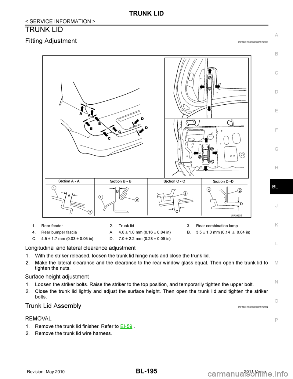
Longitudinal and latera l clearance adjustment
1. With the striker released, loosen the trunk lid hinge nuts and close the trunk lid.
2. Make the lateral clearance and the clearance to the rear window glass equal. Then open the trunk lid to
tighten the nuts.
Surface height adjustment
1. Loosen the striker bolts. Raise the striker to t he top position, and temporarily tighten the upper bolt.
2. Close the trunk lid lightly and adjust the surface height. Then open the trunk lid and tighten the striker bolts.
Trunk Lid AssemblyINFOID:0000000005929394
REMOVAL
1. Remove the trunk lid finisher. Refer to EI-59 .
2. Remove the trunk lid wire harness.
1. Rear fender 2. Trunk lid3. Rear combination lamp
4. Rear bumper fascia A. 4.0 ± 1.0 mm (0.16 ± 0.04 in) B. 3.5 ± 1.0 mm (0.14 ± 0.04 in)
C. 4.5 ± 1.7 mm (0.03 ± 0.06 in) D. 7.0 ± 2.2 mm (0.28 ± 0.09 in)
LIIA2932E
Revision: May 2010 2011 Versa