2011 NISSAN LATIO brake
[x] Cancel search: brakePage 2697 of 3787
FSU-12
< SERVICE INFORMATION >
COIL SPRING AND STRUT
COIL SPRING AND STRUT
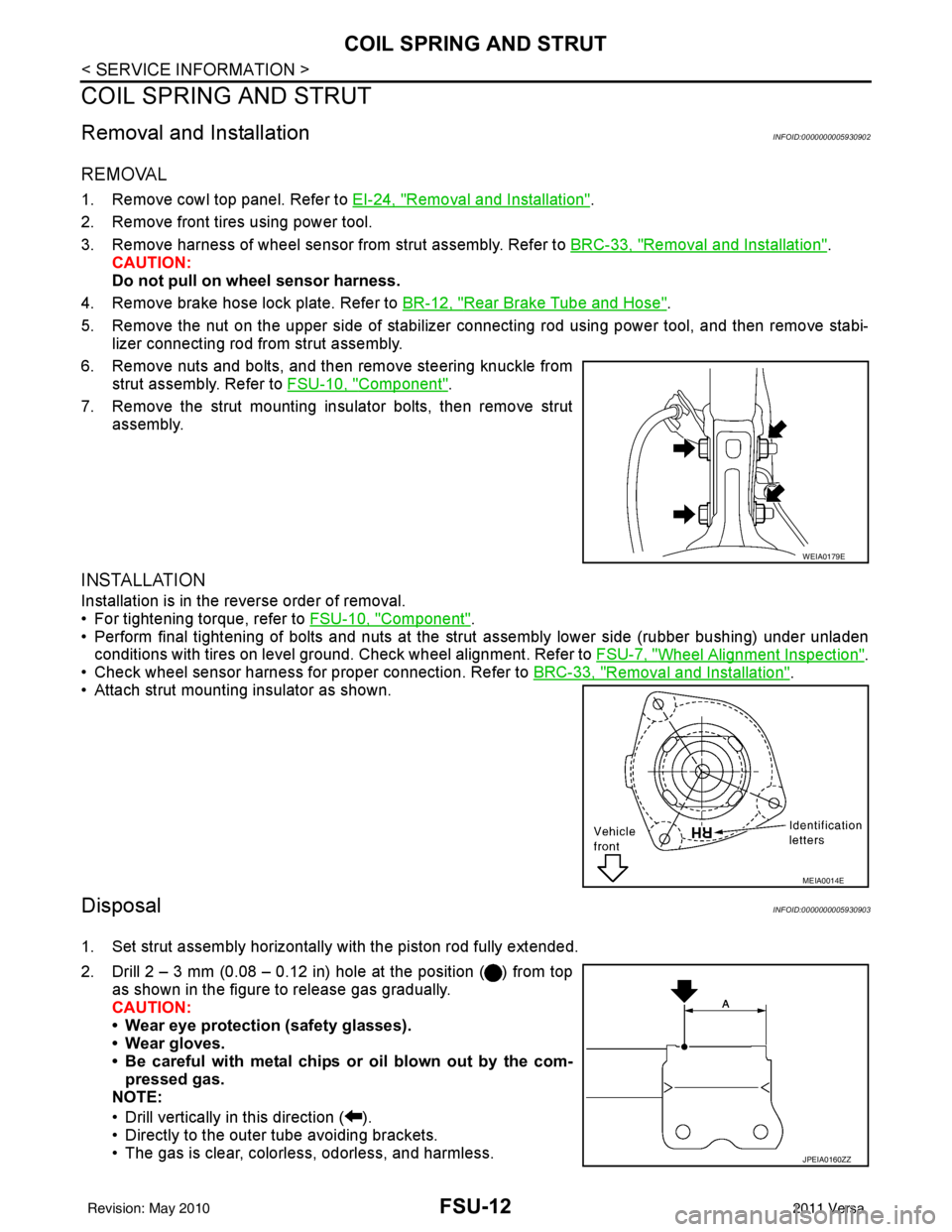
Removal and InstallationINFOID:0000000005930902
REMOVAL
1. Remove cowl top panel. Refer to EI-24, "Removal and Installation".
2. Remove front tires using power tool.
3. Remove harness of wheel sensor from strut assembly. Refer to BRC-33, "
Removal and Installation".
CAUTION:
Do not pull on wheel sensor harness.
4. Remove brake hose lock plate. Refer to BR-12, "
Rear Brake Tube and Hose".
5. Remove the nut on the upper side of stabilizer connecting rod using power tool, and then remove stabi- lizer connecting rod from strut assembly.
6. Remove nuts and bolts, and then remove steering knuckle from strut assembly. Refer to FSU-10, "
Component".
7. Remove the strut mounting insulator bolts, then remove strut assembly.
INSTALLATION
Installation is in the reverse order of removal.
• For tightening torque, refer to FSU-10, "
Component".
• Perform final tightening of bolts and nuts at the strut assembly lower side (rubber bushing) under unladen
conditions with tires on level ground. Check wheel alignment. Refer to FSU-7, "
Wheel Alignment Inspection".
• Check wheel sensor harness for proper connection. Refer to BRC-33, "
Removal and Installation".
• Attach strut mounting insulator as shown.
DisposalINFOID:0000000005930903
1. Set strut assembly horizontally with the piston rod fully extended.
2. Drill 2 – 3 mm (0.08 – 0.12 in) hole at the position ( ) from top
as shown in the figure to release gas gradually.
CAUTION:
• Wear eye protection (safety glasses).
• Wear gloves.
• Be careful with metal chips or oil blown out by the com-pressed gas.
NOTE:
• Drill vertically in this direction ( ).
• Directly to the outer tube avoiding brackets.
• The gas is clear, colorless, odorless, and harmless.
WEIA0179E
MEIA0014E
JPEIA0160ZZ
Revision: May 2010 2011 Versa
Page 2707 of 3787
PRECAUTIONSGI-3
< SERVICE INFORMATION >
C
DE
F
G H
I
J
K L
M B
GI
N
O P
2. Use the Intelligent Key or mechanical key to turn the ignition switch to the ″ACC ″ position. At this time, the
steering lock will be released.
3. Disconnect both battery cables. The steering lock will remain released and the steering wheel can be
rotated.
4. Perform the necessary repair operation.
5. When the repair work is completed, return the ignition switch to the ″LOCK ″ position before connecting
the battery cables. (At this time, the steering lock mechanism will engage.)
6. Perform a self-diagnosis check of al l control units using CONSULT-III.
General PrecautionINFOID:0000000005929711
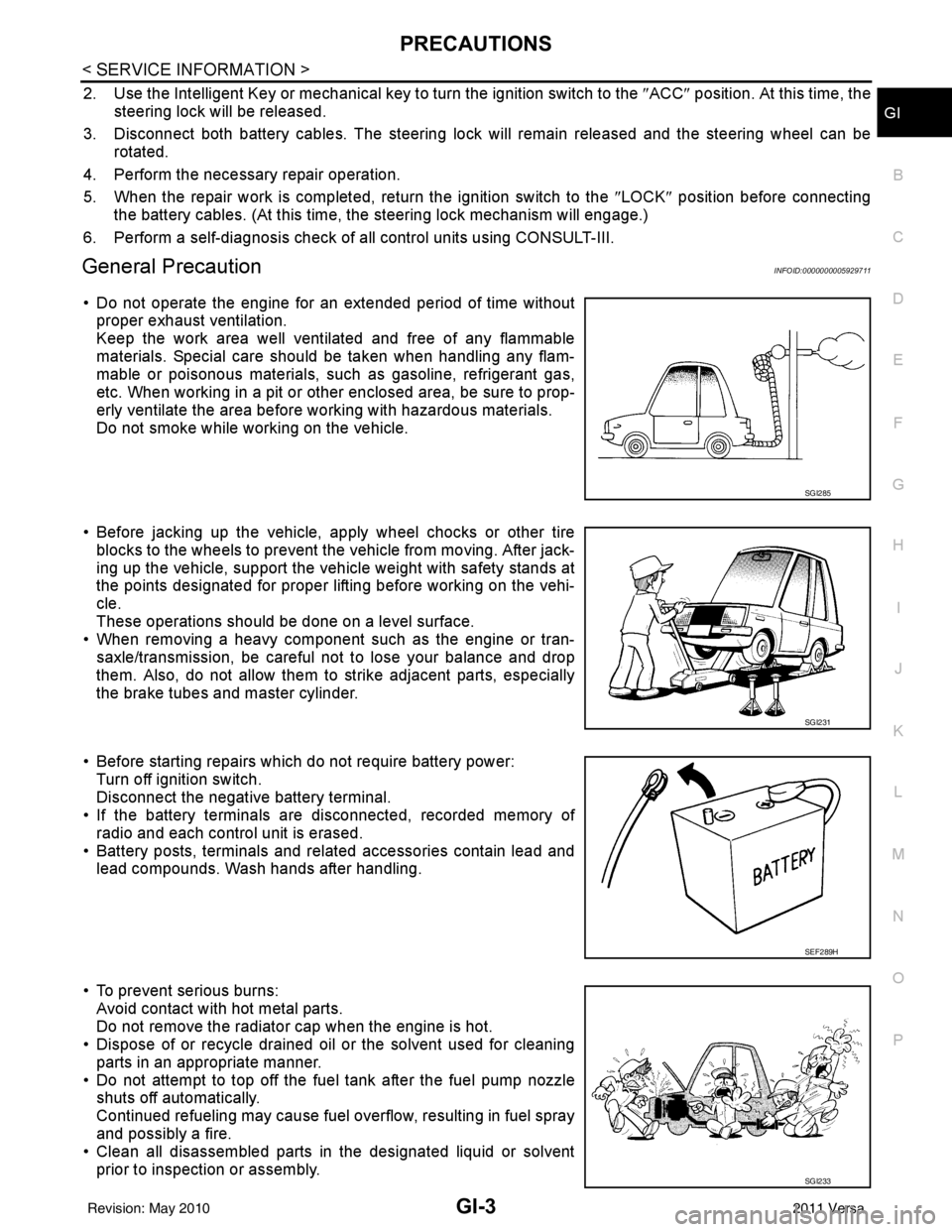
• Do not operate the engine for an extended period of time without
proper exhaust ventilation.
Keep the work area well ventilated and free of any flammable
materials. Special care should be taken when handling any flam-
mable or poisonous materials, such as gasoline, refrigerant gas,
etc. When working in a pit or ot her enclosed area, be sure to prop-
erly ventilate the area before working with hazardous materials.
Do not smoke while working on the vehicle.
• Before jacking up the vehicle, apply wheel chocks or other tire blocks to the wheels to prevent t he vehicle from moving. After jack-
ing up the vehicle, support the vehicle weight with safety stands at
the points designated for proper lifting before working on the vehi-
cle.
These operations should be done on a level surface.
• When removing a heavy component such as the engine or tran-
saxle/transmission, be careful not to lose your balance and drop
them. Also, do not allow them to strike adjacent parts, especially
the brake tubes and master cylinder.
• Before starting repairs which do not require battery power: Turn off ignition switch.
Disconnect the negative battery terminal.
• If the battery terminals are disconnected, recorded memory of
radio and each control unit is erased.
• Battery posts, terminals and related accessories contain lead and lead compounds. Wash hands after handling.
• To prevent serious burns: Avoid contact with hot metal parts.
Do not remove the radiator cap when the engine is hot.
• Dispose of or recycle drained oil or the solvent used for cleaning
parts in an appropriate manner.
• Do not attempt to top off the fuel tank after the fuel pump nozzle shuts off automatically.
Continued refueling may cause fuel overflow, resulting in fuel spray
and possibly a fire.
• Clean all disassembled parts in the designated liquid or solvent
prior to inspection or assembly.
SGI285
SGI231
SEF289H
SGI233
Revision: May 2010 2011 Versa
Page 2713 of 3787
HOW TO USE THIS MANUALGI-9
< SERVICE INFORMATION >
C
DE
F
G H
I
J
K L
M B
GI
N
O P
SYMBOLS
How to Follow Trouble DiagnosisINFOID:0000000005929724
DESCRIPTION
NOTICE:
Trouble diagnoses indicate work procedures required to diagnose problems effectively. Observe the following
instructions before diagnosing.
1. Before performing trouble diagno ses, read the “Preliminary Check” , the “Symptom Chart” or the
“Work Flow”.
2. After repairs, re-check that the prob lem has been completely eliminated.
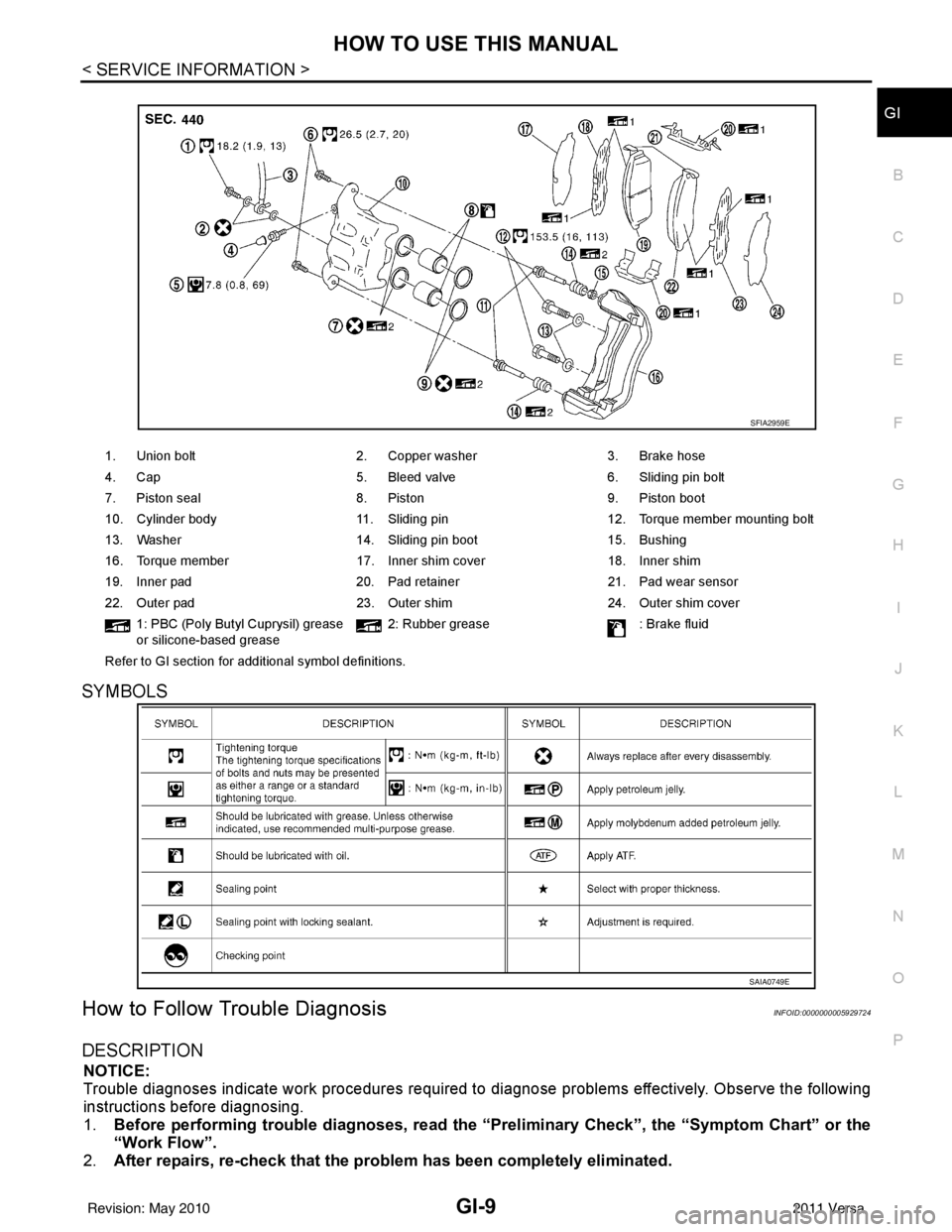
1. Union bolt 2. Copper washer3. Brake hose
4. Cap 5. Bleed valve6. Sliding pin bolt
7. Piston seal 8. Piston9. Piston boot
10. Cylinder body 11. Sliding pin12. Torque member mounting bolt
13. Washer 14. Sliding pin boot15. Bushing
16. Torque member 17. Inner shim cover18. Inner shim
19. Inner pad 20. Pad retainer21. Pad wear sensor
22. Outer pad 23. Outer shim24. Outer shim cover
1: PBC (Poly Butyl Cuprysil) grease
or silicone-based grease 2: Rubber grease
: Brake fluid
Refer to GI section for additional symbol definitions.
SFIA2959E
SAIA0749E
Revision: May 2010 2011 Versa
Page 2722 of 3787
GI-18
< SERVICE INFORMATION >
HOW TO USE THIS MANUAL
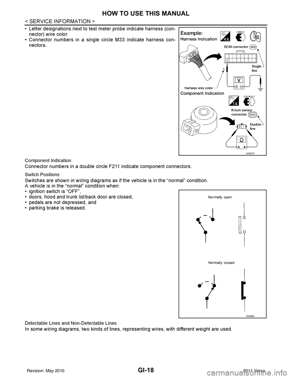
• Letter designations next to test meter probe indicate harness (con-nector) wire color.
• Connector numbers in a single circle M33 indicate harness con-
nectors.
Component Indication
Connector numbers in a double circle F211 indicate component connectors.
Switch Positions
Switches are shown in wiring diagrams as if the vehicle is in the “normal” condition.
A vehicle is in the “normal” condition when:
• ignition switch is “OFF”,
• doors, hood and trunk lid/back door are closed,
• pedals are not depressed, and
• parking brake is released.
Detectable Lines and Non-Detectable Lines
In some wiring diagrams, two kinds of lines, r epresenting wires, with different weight are used.
AGI070
SGI860
Revision: May 2010 2011 Versa
Page 2742 of 3787
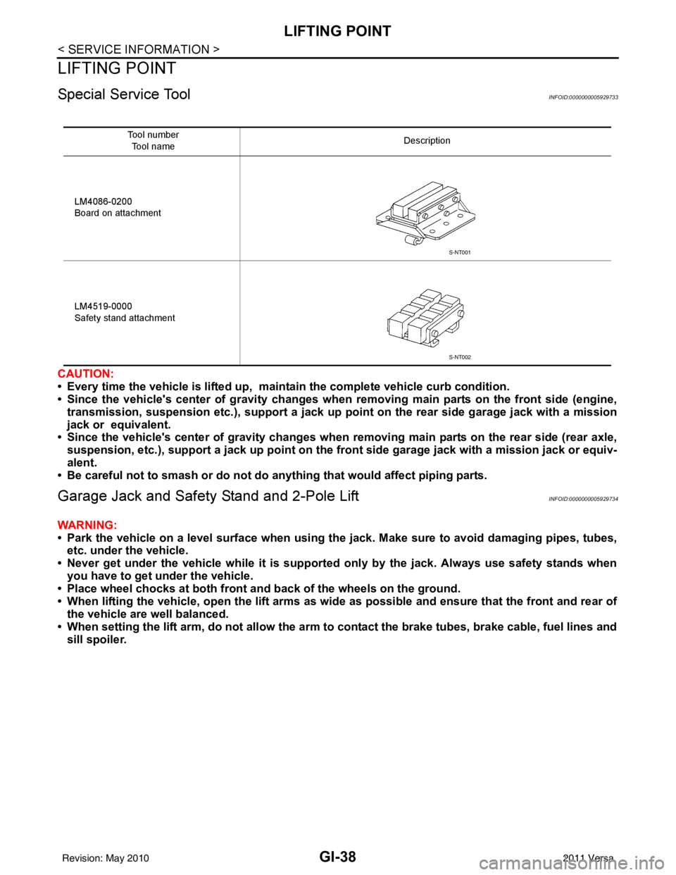
GI-38
< SERVICE INFORMATION >
LIFTING POINT
LIFTING POINT
Special Service ToolINFOID:0000000005929733
CAUTION:
• Every time the vehicle is lifted up, maintain the complete vehicle curb condition.
• Since the vehicle's center of gravity changes when removing main parts on the front side (engine,
transmission, suspension etc.), support a jack up point on the rear side garage jack with a mission
jack or equivalent.
• Since the vehicle's center of gravity changes when removing main parts on the rear side (rear axle,
suspension, etc.), support a jack up point on the front side garage jack with a mission jack or equiv-
alent.
• Be careful not to smash or do not do an ything that would affect piping parts.
Garage Jack and Safety Stand and 2-Pole LiftINFOID:0000000005929734
WARNING:
• Park the vehicle on a level surface when using the jack. Make sure to avoid damaging pipes, tubes,
etc. under the vehicle.
• Never get under the vehicle while it is supported only by the jack. Always use safety stands when you have to get under the vehicle.
• Place wheel chocks at both front an d back of the wheels on the ground.
• When lifting the vehicle, open the lift arms as wid e as possible and ensure that the front and rear of
the vehicle are well balanced.
• When setting the lift arm, do not allow the arm to contact the brake tubes, brake cable, fuel lines and
sill spoiler.
Tool number
Tool name Description
LM4086-0200
Board on attachment
LM4519-0000
Safety stand attachment
S-NT001
S-NT002
Revision: May 2010 2011 Versa
Page 2744 of 3787
GI-40
< SERVICE INFORMATION >
TOW TRUCK TOWING
TOW TRUCK TOWING
Tow Truck TowingINFOID:0000000005929736
CAUTION:
• Never tow a CVT model with the rear wheels raised and the front wheels on the ground. This may
cause serious and expensive damage to the transaxle. If it is necessary to tow the vehicle with the
rear wheels raised, always use towi ng dollies under the front wheels.
• Never tow a CVT model from the rear (that is backw ard) with four wheels on the ground. This may
cause serious and expensive damage to the transaxle.
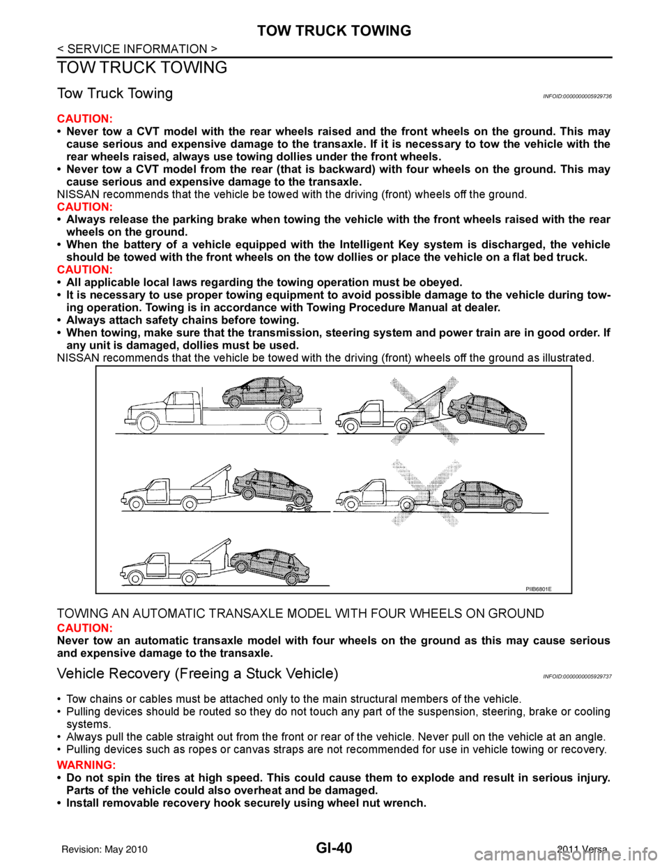
NISSAN recommends that the vehicle be towed with the driving (front) wheels off the ground.
CAUTION:
• Always release the parking brake when towing the veh icle with the front wheels raised with the rear
wheels on the ground.
• When the battery of a vehicle equipped with th e Intelligent Key system is discharged, the vehicle
should be towed with the front wheels on the tow dollies or place the vehicle on a flat bed truck.
CAUTION:
• All applicable local laws regarding the towing operation must be obeyed.
• It is necessary to use proper towi ng equipment to avoid possible damage to the vehicle during tow-
ing operation. To wing is in accordance with Towing Procedure Manual at dealer.
• Always attach safety chains before towing.
• When towing, make sure that the transmission, steering system and power train are in good order. If
any unit is damaged, dollies must be used.
NISSAN recommends that the vehicle be towed with the driving (front) wheels off the ground as illustrated.
TOWING AN AUTOMATIC TRANSAXLE MODEL WITH FOUR WHEELS ON GROUND
CAUTION:
Never tow an automatic transaxle model with four wheels on the ground as this may cause serious
and expensive damage to the transaxle.
Vehicle Recovery (Freeing a Stuck Vehicle)INFOID:0000000005929737
• Tow chains or cables must be attached only to the main structural members of the vehicle.
• Pulling devices should be routed so they do not touch any part of the suspension, steering, brake or cooling
systems.
• Always pull the cable straight out from the front or r ear of the vehicle. Never pull on the vehicle at an angle.
• Pulling devices such as ropes or canvas straps are not recommended for use in vehicle towing or recovery.
WARNING:
• Do not spin the tires at high sp eed. This could cause them to explode and result in serious injury.
Parts of the vehicle could also overheat and be damaged.
• Install removable recovery hook securely using wheel nut wrench.
PIIB6801E
Revision: May 2010 2011 Versa
Page 2872 of 3787
![NISSAN LATIO 2011 Service Repair Manual LAN-26
< SERVICE INFORMATION >[CAN]
CAN COMMUNICATION SYSTEM
CAN COMMUNICATION SYSTEM
CAN System Specification ChartINFOID:0000000005928533
NOTE:
Refer to
LAN-17, "
Trouble Diagnosis Procedure" for h NISSAN LATIO 2011 Service Repair Manual LAN-26
< SERVICE INFORMATION >[CAN]
CAN COMMUNICATION SYSTEM
CAN COMMUNICATION SYSTEM
CAN System Specification ChartINFOID:0000000005928533
NOTE:
Refer to
LAN-17, "
Trouble Diagnosis Procedure" for h](/manual-img/5/57357/w960_57357-2871.png)
LAN-26
< SERVICE INFORMATION >[CAN]
CAN COMMUNICATION SYSTEM
CAN COMMUNICATION SYSTEM
CAN System Specification ChartINFOID:0000000005928533
NOTE:
Refer to
LAN-17, "
Trouble Diagnosis Procedure" for how to use CAN system specification chart.
×: Applicable
VEHICLE EQUIPMENT IDENTIFICATION INFORMATION
NOTE:
Check CAN system type from the vehicle shape and equipment.
Body type Sedan Hatchback/Sedan Hatchback
Axle 2WD
Engine HR16DE MR18DE
Transmission M/TA/T M/T A/TCVT
Brake control — ABS — ABS — ABS VDC — ABS VDC
Intelligent Key system ××
CAN system type 12345678910111213
1. VDC OFF switch 2. ABS warning lamp
ABS: USA
: Canada 3. Ignition knob
A. With VDC B. With ABS C. With Intelligent Key system
ALMIA0478ZZ
Revision: May 2010 2011 Versa
Page 2874 of 3787
![NISSAN LATIO 2011 Service Repair Manual LAN-28
< SERVICE INFORMATION >[CAN]
CAN COMMUNICATION SYSTEM
*1: A/T models
*2: CVT models
*3: Models with VDC
*4: Models for Canada
*5: Models for USA
*6: Models without ABS
NOTE:
CAN data of the air NISSAN LATIO 2011 Service Repair Manual LAN-28
< SERVICE INFORMATION >[CAN]
CAN COMMUNICATION SYSTEM
*1: A/T models
*2: CVT models
*3: Models with VDC
*4: Models for Canada
*5: Models for USA
*6: Models without ABS
NOTE:
CAN data of the air](/manual-img/5/57357/w960_57357-2873.png)
LAN-28
< SERVICE INFORMATION >[CAN]
CAN COMMUNICATION SYSTEM
*1: A/T models
*2: CVT models
*3: Models with VDC
*4: Models for Canada
*5: Models for USA
*6: Models without ABS
NOTE:
CAN data of the air bag diagnosis sensor unit is not used by usual service work, thus it is omitted.
KEY warning lamp signal
T R
LOCK warning lamp signal T R
Panic alarm request signal RT
Fuel level sensor signal RT
Overdrive control switch signal TR R
Parking brake switch signal
*3TR
Stop lamp switch signal T R R
Vehicle speed signal RRRR T
RRR T R
R
*6T*6
Steering angle sensor signal*3TR
ABS warning lamp signal RT
Brake warning lamp signal RT
SLIP indicator lamp signal
*3RT
VDC OFF indicator lamp signal
*3RT
VDC warning lamp signal
*3RT
A/T check indicator signal RT
A/T self-diagnosis signal R T
Input speed signal R T
OD OFF indicator signal RT
Output shaft revolution signal R T T
Shift position indicator signal R
R
*3TT
CVT self-diagnosis signal R T
Input shaft revolution signal R T
OD OFF indicator signal RT
Front wiper stop position signal R T
High beam status signal R T
Low beam status signal R T
Oil pressure switch signal R RR T
Rear window defogger control signal R T
Signal name/Connecting unit
ECM
BCM
EPS
I-KEY M&A
STRG ABS
TCM
*1
TCM
*2
IPDM-E
Revision: May 2010 2011 Versa