2011 NISSAN LATIO automatic transmission fluid
[x] Cancel search: automatic transmission fluidPage 18 of 3787

AT-1
TRANSMISSION/TRANSAXLE
DE
F
G H
I
J
K L
M
SECTION AT
A
B
AT
N
O P
CONTENTS
AUTOMATIC TRANSAXLE
SERVICE INFORMATION .. ..........................5
INDEX FOR DTC ............................................ .....5
Alphabetical Index ............................................... ......5
DTC No. Index ..........................................................5
PRECAUTIONS ...................................................7
Precaution for Supplemental Restraint System
(SRS) "AIR BAG" and "SEAT BELT PRE-TEN-
SIONER" ............................................................. ......
7
Precaution Necessary for Steering Wheel Rota-
tion After Battery Disconnect ............................... ......
7
Precaution for On Board Diagnosis (OBD) System
of A/T and Engine .....................................................
8
Precaution .................................................................8
Service Notice or Precaution .....................................9
PREPARATION ..................................................11
Special Service Tool ........................................... ....11
Commercial Service Tool ........................................14
A/T FLUID ...........................................................17
Checking A/T Fluid ..................................................17
Changing A/T Fluid .................................................17
A/T Fluid Cooler Cleaning .......................................18
A/T CONTROL SYSTEM ....................................21
Cross-Sectional View ..............................................21
Shift Mechanism .................................................. ....22
TCM Function ..........................................................30
CAN Communication ...............................................31
Input/Output Signal of TCM .....................................31
Line Pressure Control .............................................32
Shift Control ........................................................ ....33
Lock-up Control .......................................................34
Engine Brake Control (Overrun Clutch Control) ......35
Control Valve ....................................................... ....37
Centrifugal Cancel Mechanism ...............................37
ON BOARD DIAGNOSTIC (OBD) SYSTEM ......39
Introduction ......................................................... ....39
OBD-II Function for A/T System ..............................39
One or Two Trip Detection Logic of OBD-II ......... ....39
OBD-II Diagnostic Trouble Code (DTC) ..................39
Malfunction Indicator Lamp (MIL) ............................41
TROUBLE DIAGNOSIS ....................................42
DTC Inspection Priority Chart ..................................42
Fail-Safe ..................................................................42
How to Perform Trouble Diagnosis for Quick and
Accurate Repair .......................................................
43
A/T Electrical Parts Location ...................................49
Circuit Diagram ........................................................50
Inspections Before Trouble Diagnosis .....................51
Road Test ................................................................55
Check Before Engine Is Started ..............................56
Check at Idle ............................................................56
Cruise Test - Part 1 .................................................58
Cruise Test - Part 2 .................................................61
Cruise Test - Part 3 .................................................62
Vehicle Speed at Which Gear Shifting Occurs ........64
Vehicle Speed at Which Lock-up Occurs/Releas-
es .............................................................................
64
Symptom Chart ........................................................65
TCM Terminal and Reference Value .......................75
CONSULT-III Function (TRANSMISSION) .......... ....77
Diagnosis Procedure without CONSULT-III ............82
U1000 CAN COMM CIRCUIT ...........................87
Description ........................................................... ....87
On Board Diagnosis Logic .......................................87
Possible Cause ........................................................87
DTC Confirmation Procedure ..................................87
Wiring Diagram - AT - CAN .....................................88
Diagnosis Procedure ...............................................89
P0705 TRANSMISSION RANGE SWITCH A ...90
Description ...............................................................90
CONSULT-III Reference Value in Data Monitor
Mode .................................................................... ....
90
On Board Diagnosis Logic .......................................90
Possible Cause ........................................................90
DTC Confirmation Procedure ..................................90
Revision: May 2010 2011 Versa
Page 26 of 3787

PRECAUTIONSAT-9
< SERVICE INFORMATION >
DE
F
G H
I
J
K L
M A
B
AT
N
O P
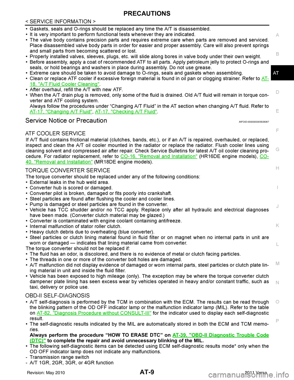
• Gaskets, seals and O-rings should be replaced any time the A/T is disassembled.
• It is very important to perform func tional tests whenever they are indicated.
• The valve body contains precision parts and requires extreme care when parts are removed and serviced.
Place disassembled valve body parts in order for easier and proper assembly. Care will also prevent springs
and small parts from becoming scattered or lost.
• Properly installed valves, sleeves, plugs, etc. will slide along bores in valve body under their own weight.
• Before assembly, apply a coat of recommended ATF to all parts. Apply petroleum jelly to protect O-rings and seals, or hold bearings and washers in pl ace during assembly. Do not use grease.
• Extreme care should be taken to avoid damage to O-rings, seals and gaskets when assembling.
• Clean or replace ATF cooler if excessive foreign material is found in oil pan or clogging strainer. Refer to AT-
18, "A/T Fluid Cooler Cleaning".
• After overhaul, refill the A/T with new ATF.
• When the A/T drain plug is removed, only some of the fluid is drained. Old A/T fluid will remain in torque con- verter and ATF cooling system.
Always follow the procedures under “Changing A/T Fluid” in the AT section when changing A/T fluid. Refer to
AT-17, "
Changing A/T Fluid", AT-17, "Checking A/T Fluid".
Service Notice or PrecautionINFOID:0000000005928067
ATF COOLER SERVICE
If A/T fluid contains frictional material (clutches, bands, etc.), or if an A/T is repaired, overhauled, or replaced,
inspect and clean the A/T oil cooler mounted in the radiator or replace the radiator. Flush cooler lines using
cleaning solvent and compressed air after repair. Check Service Bulletins for latest A/T oil cooler cleaning pro-
cedure. For radiator replacement, refer to CO-16, "
Removal and Installation" (HR16DE engine models), CO-
40, "Removal and Installation" (MR18DE engine models).
TORQUE CONVERTER SERVICE
The torque converter should be replaced under any of the following conditions:
• External leaks in the hub weld area.
• Converter hub is scored or damaged.
• Converter pilot is broken, damaged or fits poorly into crankshaft.
• Steel particles are found after flushing the cooler and cooler lines.
• Pump is damaged or steel particles are found in the converter.
• Vehicle has TCC shudder and/or no TCC apply. Replace only after all hydraulic and electrical diagnoses
have been made. (Converter clutch material may be glazed.)
• Converter is contaminated with engi ne coolant containing antifreeze.
• Internal malfunction of stator roller clutch.
• Heavy clutch debris due to overheating (blue converter).
• Steel particles or clutch lining material found in flui d filter or on magnet when no internal parts in unit are
worn or damaged — indicates that lining material came from converter.
The torque converter should not be replaced if:
• The fluid has an odor, is discolored, and there is no evidence of metal or clutch facing particles.
• The threads in one or more of the converter bolt holes are damaged.
• A/T malfunction did not display evidence of damaged or worn internal parts, steel particles or clutch plate lin-
ing material in unit and inside the fluid filter.
• Vehicle has been exposed to high mileage (only). The e xception may be where the torque converter clutch
dampener plate lining has seen excess wear by vehicles operated in heavy and/or constant traffic, such as
taxi, delivery or police use.
OBD-II SELF-DIAGNOSIS
• A/T self-diagnosis is performed by the TCM in combination with the ECM. The results can be read through the blinking pattern of the OD OFF indicator lamp or the malfunction indicator lamp (MIL). Refer to the table
on AT-82, "
Diagnosis Procedure without CONSULT-III" for the indicator used to display each self-diagnostic
result.
• The self-diagnostic results indicated by the MIL are automatically stored in both the ECM and TCM memo- ries.
Always perform the procedure “HOW TO ERASE DTC” on AT-39, "
OBD-II Diagnostic Trouble Code
(DTC)" to complete the repair and avoid unnecessary blinking of the MIL.
• The following self-diagnostic items can be detected us ing ECM self-diagnostic results mode* only when the
OD OFF indicator lamp does not indicate any malfunctions.
- Transmission range switch
- A/T 1GR, 2GR, 3GR, or 4GR function
Revision: May 2010 2011 Versa
Page 47 of 3787

AT-30
< SERVICE INFORMATION >
A/T CONTROL SYSTEM
TCM Function
INFOID:0000000005928075
The function of the TCM is to:
• Receive input signals sent from various switches and sensors.
• Determine required line pressure, shifting poi nt, lock-up operation, and engine brake operation.
• Send required output signals to the respective solenoids.
CONTROL SYSTEM OUTLINE
The automatic transaxle senses vehicle operating conditions through various sensors or signals. It always
controls the optimum shift position and reduces shifting and lock-up shocks.
SAT381J
SWITCHES & SENSORS
⇒TCM
⇒ACTUATORS
Transmission range switch
Accelerator pedal position signal
Closed throttle position signal
Wide open throttle position signal
Engine speed signal
A/T fluid temperature sensor
Output speed sensor
Input speed sensor
Vehicle speed signal
Overdrive control switch signal
Stop lamp switch signal Shift control
Line pressure control
Lock-up control
Overrun clutch control
Fail-safe control
Self-diagnosis
CONSULT-III communication
line control
Shift solenoid valve A
Shift solenoid valve B
Overrun clutch solenoid valve
Torque converter clutch solenoid
valve
Line pressure solenoid valve
OD OFF indicator lamp
Revision: May 2010
2011 Versa
Page 390 of 3787

SERVICE DATA AND SPECIFICATIONS (SDS)AT-373
< SERVICE INFORMATION >
DE
F
G H
I
J
K L
M A
B
AT
N
O P
SERVICE DATA AND SPECIFICATIONS (SDS)
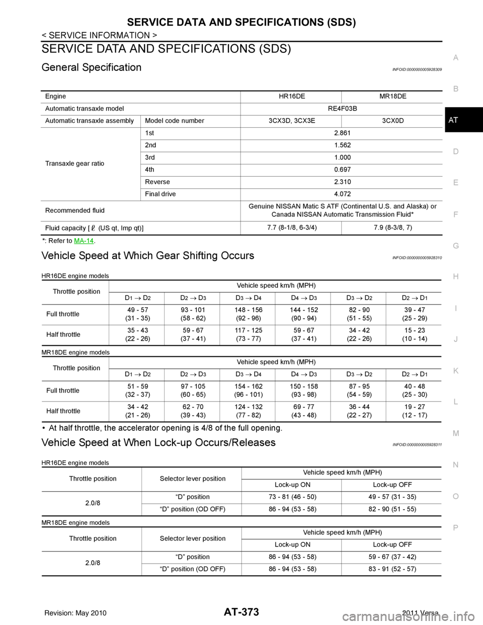
General SpecificationINFOID:0000000005928309
*: Refer to MA-14.
Vehicle Speed at Which Gear Shifting OccursINFOID:0000000005928310
HR16DE engine models
MR18DE engine models
• At half throttle, the accelerator opening is 4/8 of the full opening.
Vehicle Speed at When Lock-up Occurs/ReleasesINFOID:0000000005928311
HR16DE engine models
MR18DE engine models
Engine HR16DEMR18DE
Automatic transaxle model RE4F03B
Automatic transaxle assembly Model code number 3CX3D, 3CX3E3CX0D
Transaxle gear ratio 1st
2.861
2nd 1.562
3rd 1.000
4th 0.697
Reverse 2.310
Final drive 4.072
Recommended fluid Genuine NISSAN Matic S ATF (Continental U.S. and Alaska) or
Canada NISSAN Automatic Transmission Fluid*
Fluid capacity [ (US qt, Imp qt)] 7.7 (8-1/8, 6-3/4)
7.9 (8-3/8, 7)
Throttle position Vehicle speed km/h (MPH)
D1 → D2D2 → D3D3 → D4D4 → D3D3 → D2D2 → D1
Full throttle 49 - 57
(31 - 35) 93 - 101
(58 - 62) 148 - 156
(92 - 96) 144 - 152
(90 - 94) 82 - 90
(51 - 55) 39 - 47
(25 - 29)
Half throttle 35 - 43
(22 - 26) 59 - 67
(37 - 41) 117 - 125
(73 - 77) 59 - 67
(37 - 41) 34 - 42
(22 - 26) 15 - 23
(10 - 14)
Throttle position Vehicle speed km/h (MPH)
D
1 → D2D2 → D3D3 → D4D4 → D3D3 → D2D2 → D1
Full throttle 51 - 59
(32 - 37) 97 - 105
(60 - 65) 154 - 162
(96 - 101) 150 - 158
(93 - 98) 87 - 95
(54 - 59) 40 - 48
(25 - 30)
Half throttle 34 - 42
(21 - 26) 62 - 70
(39 - 43) 124 - 132
(77 - 82) 69 - 77
(43 - 48) 36 - 44
(22 - 27) 19 - 27
(12 - 17)
Throttle position Selector lever position Vehicle speed km/h (MPH)
Lock-up ON Lock-up OFF
2.0/8 “D” position
73 - 81 (46 - 50) 49 - 57 (31 - 35)
“D” position (OD OFF) 86 - 94 (53 - 58) 82 - 90 (51 - 55)
Throttle position Selector lever position Vehicle speed km/h (MPH)
Lock-up ON Lock-up OFF
2.0/8 “D” position
86 - 94 (53 - 58) 59 - 67 (37 - 42)
“D” position (OD OFF) 86 - 94 (53 - 58) 83 - 91 (52 - 57)
Revision: May 2010 2011 Versa
Page 1066 of 3787
![NISSAN LATIO 2011 Service Repair Manual PRECAUTIONSCVT-11
< SERVICE INFORMATION > [RE0F08B]
D
E
F
G H
I
J
K L
M A
B
CVT
N
O P
• When connecting or disconnecting pin connectors into or
from TCM, take care not to damage pin terminals (bend NISSAN LATIO 2011 Service Repair Manual PRECAUTIONSCVT-11
< SERVICE INFORMATION > [RE0F08B]
D
E
F
G H
I
J
K L
M A
B
CVT
N
O P
• When connecting or disconnecting pin connectors into or
from TCM, take care not to damage pin terminals (bend](/manual-img/5/57357/w960_57357-1065.png)
PRECAUTIONSCVT-11
< SERVICE INFORMATION > [RE0F08B]
D
E
F
G H
I
J
K L
M A
B
CVT
N
O P
• When connecting or disconnecting pin connectors into or
from TCM, take care not to damage pin terminals (bend or
break).
When connecting pin connectors make sure that there are not
any bends or breaks on TCM pin terminal.
• Before replacing TCM, perform TCM input/output signal
inspection and make sure whether TCM functions properly or
not. CVT-46, "
TCM Terminal and Reference Value".
• After performing each TROUBL E DIAGNOSIS, perform “DTC
Confirmation Procedure”.
If the repair is completed the DTC should not be displayed in
the “DTC Confirmation Procedure”.
• Always use the specified br and of CVT fluid. Refer to MA-14, "
Flu-
ids and Lubricants".
• Use lint-free paper, not cloth rags, during work.
• After replacing the CVT fluid, dispose of the waste oil using the methods prescribed by law, ordinance, etc.
Service Notice or PrecautionINFOID:0000000005928726
CVT FLUID COOLER SERVICE
If CVT fluid contains friction material (clutches, brakes , etc.), or if an CVT is replaced, inspect and clean the
CVT fluid cooler mounted in the radiator or replace the radiator. Flush cooler lines using cleaning solvent and
compressed air after repair. For CVT fluid cooler cleaning procedure, refer to CVT-15, "
CVT Fluid Cooler
Cleaning". For radiator replacement, refer to CO-40.
OBD-II SELF-DIAGNOSIS
• CVT self-diagnosis is performed by the TCM in combination with the ECM. The results can be read through
the blinking pattern of the malfunction indi cator lamp (MIL). Refer to the table on CVT-48, "
CONSULT-III
Function (TRANSMISSION)" for the indicator used to display each self-diagnostic result.
• The self-diagnostic results indicated by the MIL are automatically stored in both the ECM and TCM memo- ries.
Always perform the procedure on CVT-27, "
OBD-II Diagnostic Trouble Code (DTC)" to complete the
repair and avoid unnecessary blinking of the MIL.
For details of OBD-II, refer to EC-541, "
Introduction".
• Certain systems and components, especially those re lated to OBD, may use the new style slide-lock-
ing type harness connector. For description and how to disconnect, refer to PG-65
.
ATFTEMP COUNT Conversion Table INFOID:0000000005928727
SEF291H
MEF040DA
SEF217U
Revision: May 2010 2011 Versa
Page 2724 of 3787

GI-20
< SERVICE INFORMATION >
HOW TO USE THIS MANUAL
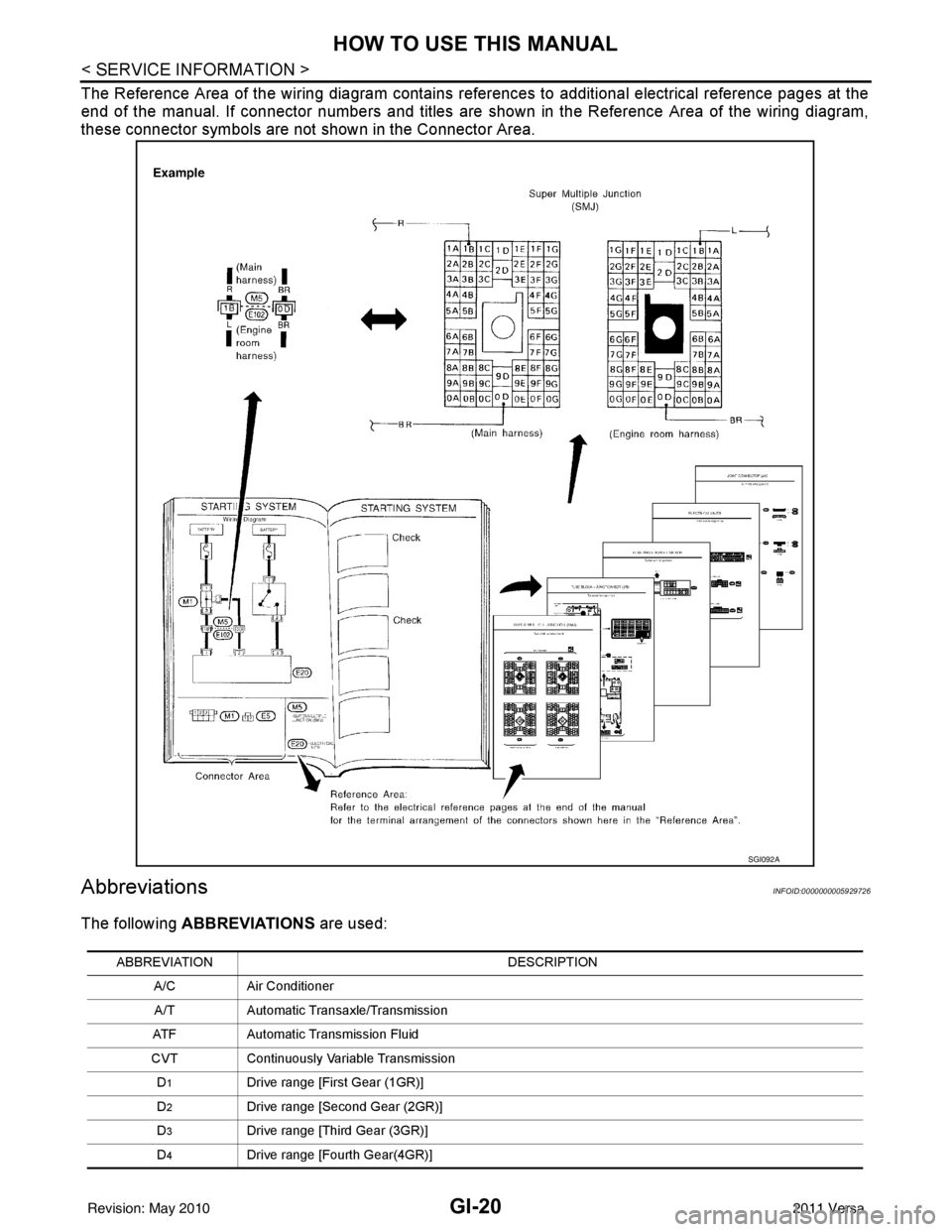
The Reference Area of the wiring diagram contains references to additional electrical reference pages at the
end of the manual. If connector numbers and titles are shown in the Reference Area of the wiring diagram,
these connector symbols are not shown in the Connector Area.
AbbreviationsINFOID:0000000005929726
The following ABBREVIATIONS are used:
SGI092A
ABBREVIATION DESCRIPTION
A/C Air Conditioner
A/T Automatic Transaxle/Transmission
ATF Automatic Transmission Fluid
CVT Continuously Variable Transmission
D
1Drive range [First Gear (1GR)]
D
2Drive range [Second Gear (2GR)]
D
3Drive range [Third Gear (3GR)]
D
4Drive range [Fourth Gear(4GR)]
Revision: May 2010 2011 Versa
Page 3182 of 3787

PERIODIC MAINTENANCEMA-11
< SERVICE INFORMATION >
C
DE
F
G H
I
J
K
M A
B
MA
N
O P
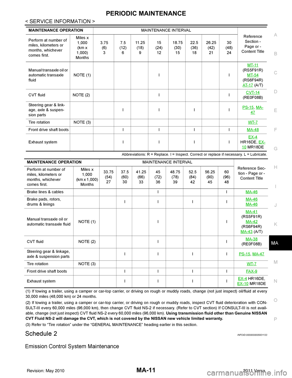
Abbreviations: R = Replace. I = Inspect. Corr ect or replace if necessary. L = Lubricate.
(1) If towing a trailer, using a camper or car-top carrier, or driving on rough or muddy roads, change (not just inspect) oil/f luid at every
30,000 miles (48,000 km) or 24 months.
(2) If towing a trailer, using a camper or car-top carrier, or driving on rough or muddy roads, inspect CVT fluid deterioration with CON-
SULT-III every 60,000 miles (96,000 km), then change CVT fluid NS -2 if necessary. (Refer to CVT section) If CONSULT-III is not avail-
able, change (not just inspect) CVT fluid NS-2 every 60,000 miles (96,000 km). Using transmission fluid other than Genuine NISSAN
CVT Fluid NS-2 will damage the CVT, which is not covered by the NISSAN new vehicle limited warranty.
(3) Refer to “Tire rotation” under the “GENERAL MAINTENANCE” heading earlier in this section.
Schedule 2INFOID:0000000005931133
Emission Control System Maintenance
Manual transaxle oil or
automatic transaxle
fluidNOTE (1)
IIMT-11
(RS5F91R) MT-54
(RS6F94R)
AT- 1 7
(A/T)
CVT fluid NOTE (2) IICVT-14
(RE0F08B)
Steering gear & link-
age, axle & suspen-
sion parts IIII
PS-15
, MA-
47
Tire rotation
NOTE (3) WT-7
Front drive shaft bootsIIIIMA-48
Exhaust system IIIIEX-4
HR16DE, EX-
10 MR18DE
MAINTENANCE OPERATION
MAINTENANCE INTERVAL
Reference Section -
Page or -
Content Title
Perform at number of
miles, kilometers or
months, whichever
comes first. Miles x
1,000
(km x
1,000)
Months 3.75
(6)3 7.5
(12) 6 11 . 2 5
(18) 9 15
(24) 12 18.75
(30)15 22.5
(36) 18 26.25
(42)21 30
(48) 24
MAINTENANCE OPERATION MAINTENANCE INTERVAL
Reference Sec-tion - Page or - Content Title
Perform at number of
miles, kilometers or
months, whichever
comes first. Miles x
1,000
(km x 1,000)
Months 33.75
(54)27 37.5
(60) 30 41.25
(66)33 45
(72) 36 48.75
(78)39 52.5
(84) 42 56.25
(90)45 60
(96) 48
Brake lines & cables IIMA-46
Brake pads, rotors,
drums & linings II I I
MA-46
MA-46
Manual transaxle oil or
automatic transaxle fluidNOTE (1)
IIMA-41
(RS5F91R)
MA-42
(RS6F94R)
MA-43
(A/T)
CVT fluid NOTE (2) IIMA-38
(RE0F08B)
Steering gear & linkage,
axle & suspension parts II I I
PS-15
, MA-47
Tire rotationNOTE (3) WT-7
Front drive shaft bootsII IIFAX-9
Exhaust system II IIEX-4 HR16DE,
EX-10
MR18DE
Revision: May 2010 2011 Versa
Page 3185 of 3787

MA-14
< SERVICE INFORMATION >
RECOMMENDED FLUIDS AND LUBRICANTS
RECOMMENDED FLUIDS AND LUBRICANTS
Fluids and LubricantsINFOID:0000000005931134
*1: For further details, see “Engine Oil Recommendation”.
*2: If Genuine NISSAN gear oil is not available, API GL-4, Viscosity SAE 75W-85 may also be used as a temporary replacement. How-
ever, use Genuine NISSAN gear oil as soon as it is available.
*3: If Genuine NISSAN ge ar oil is not available, API GL-4, Viscosity SAE 75W-80 may be used as a temporary replacement. However
use Genuine NISSAN gear oil as soon as it is available.
*4: If Genuine NISSAN Matic S ATF is not available, Genuine NISSIAN Matic D ATF may also be used. Using automatic transmission
other than Genuine NISSAN Matic S or Genuine NISSIAN Matic D ATF will cause deteri oration in driveability and automatic transmis-
sion durability, and may damage the automatic transmission, which is not covered by th e NISSAN new vehicle limited warranty.
*5: Use only Genuine NISSAN CVT Fluid NS-2. Using transmission fluid other than Genuine NISSAN CVT Fluid NS-2 will dam-
age the CVT, which is not covered by the NISSAN new vehicle limited warranty.
*6: Available in mainland U.S.A. through a NISSAN dealer.
*7: For further details, see “Air conditioner specification label”. Description
Capacity (Approximate)
Recommended Fluids/Lubricants
Liter US measure Imp measure
Fuel 50.0 13 1/4 gal 11 galUnleaded gasoline with an octane
rating of at least 87 AKI (RON 91)
Engine oil
Drain and refill With oil filter
change
HR16DE 3.0 3 1/8 qt 2 5/8 qt
• Engine oil with API Certification Mark *1
• Viscosity SAE 5W-30
MR18DE 4.1 4 3/8 qt 3 5/8 qt
Without oil
filter change HR16DE 2.8
3 qt 2 1/2 qt
MR18DE 3.9 4 1/8 qt 3 3/8 qt
Dry engine (engine overhaul) HR16DE 3.5 3 3/4 qt 3 1/8 qt
MR18DE 4.9 5 1/8 qt 4 3/8 qt
Cooling system
(with reservoir at max level) HR16DE 6.3 6 5/8 qt 5 1/2 qt Genuine NISSAN Long Life Anti-
freeze / Coolant (blue) or equivalent
MR18DE 6.8 7 1/4 qt 6 qt
Manual transaxle fluid (MTF) 5MT
2.6 5 1/2 pt 4 5/8 pt Genuine NISSAN Manual Transmis-
sion Fluid (MTF) HQ Multi 75W-85 or
equivalent*2
6MT 2.0 4 1/4 pt 3 1/2 pt Genuine NISSAN gear oil (Chevron
Texaco ETL8997B) 75W-80, or
equivalent *3
Automatic transaxle fluid (ATF) HR16DE 7.7 8 1/8 qt 6 3/4 qt
Genuine NISSAN Matic S ATF*4
MR18DE 7.9 8 3/8 qt 7 qt
CVT fluid RE0F08B 6.9 7 1/4 qt 6 1/8 qt Genuine NISSAN CVT Fluid NS-2 *5
Brake and clutch fluid ———Genuine NISSAN Super Heavy Duty
Brake Fluid*6 or equivalent DOT 3
(US FMVSS No. 116)
Multi-purpose grease ——— NLGI No. 2 (Lithium soap base)
Windshield washer fluid 4.5 4 3/4 qt 4 qtGenuine NISSAN Windshield Wash-
er Concentrate Cleaner & Anti-
Freeze or equivalent
Air conditioning system refrigerant 0.45 ± 0.05 kg 0.99 ± 0.11 lb 0.99 ± 0.11 lb HFC-134a (R-134a) *7
Air conditioning system oil MR18DE -
Typ e 1
and
HR16DE
120 m
4.1 fl oz 4.2 fl oz A/C System Oil Type R (DH-PR) *7
MR18DE -
Typ e 2 100 m
3.4 fl oz 3.5 fl oz A/C System Oil Type S (DH-PS)*7
Revision: May 2010
2011 Versa