Page 3419 of 3787
PARKING BRAKE CONTROLPB-7
< SERVICE INFORMATION >
C
DE
G H
I
J
K L
M A
B
PB
N
O P
10. Remove adjusting nut and discard. Remove the front cable from the device assembly.
CAUTION:
Discard the adjusting nut, do not reuse.
INSTALLATION
Installation is in the reverse order of removal.
• Adjust clearance of rear brake shoes. Refer to PB-5, "
On-Vehicle Service".
Revision: May 2010 2011 Versa
Page 3420 of 3787
PB-8
< SERVICE INFORMATION >
SERVICE DATA AND SPECIFICATIONS (SDS)
SERVICE DATA AND SPECIFICATIONS (SDS)
Parking Brake ControlINFOID:0000000005929652
Control typeHand lever
Number of notches [under a force of 196 N (20 kg-f, 44lb-f)] 8 − 9
Number of notches when brake warning lamp comes on 1
Revision: May 2010 2011 Versa
Page 3461 of 3787

HARNESSPG-41
< SERVICE INFORMATION >
C
DE
F
G H
I
J
L
M A
B
PG
N
O P
C2 M6 W/4 : Steering lock solenoid D2 M43 W/20 : Audio unit
B3 M7 W/16 : Door mirror re mote control switch D2 M44 W/16 : Audio unit
A3 M8 W/16 : To D2 D2 M45 W/12 : Audio unit
A3 M9 W/16 : To D1 A1 M46 BR/2 : Front tweeter LH
E2 M10 GR/2 : Instrument panel antenna G1 M47 BR/2 : Front tweeter RH
G3 M11 W/4 : To B106 B2 M48 L/4 : Heated mirror relay
G4 M12 W/16 : To B101 D3 M49 W/24 : iPod ® adapter
G3 M13 W/24 : To B102 E1 M50 GR/16 : iPod ® side
G3 M14 W/24 : To B120 E2 M52 W/40 : Intelligent key unit
B4 M15 W/16 : To B23 B2 M53 W/16 : EPS control unit
B4 M16 W/24 : To B24 B3 M54 B/2 : EPS control unit
D5 M17 B/1 : Parking brake switch D2 M55 W/4 : Hazard switch
F2 M18 W/40 : BCM (body control module) B2 M57 — : Body ground
F2 M19 W/15 : BCM (body control module) C1 M60 L/2 : EPS control unit
F3 M20 B/15 : BCM (body control module) F1 M61 — : Body ground
C2 M21 W/4 : NATS antenna amp. E2 M62 W/2 : Front blower motor
B3 M22 W/16 : Data link connector C1 M63 W/4 : Torque sensor
E3 M23 W/4 : Remote keyless entry receiver C3 M64 W/8 : Steering angle sensor
C1 M24 W/40 : Combination meter A2 M69 SMJ : To E7
C3 M25 /2 : Diode-1 D2 M70 W/24 : AV control unit
B2 M26 W/6 : Ignition switch D2 M71 W/9 : AV control unit
C2 M27 GR/6 : Key switch and key lock solenoid D1 M72 B/5 : USB interface and aux jack
C2 M28 W/16 : Combination switch B2 M73 GR/6 : Key switch and ignition knob switch
C3 M29 Y/6 : Combination switch G3 M74 W/12 : To D102
C3 M30 GR/8 : Combination switch G3 M75 W/12 : To D101
E3 M32 W/4 : To M150 E1 M76 B/4 : USB interface and aux jack
D2 M33 B/15 : Front air control F2 M77 Y/4 : Front passenger air bag module
B3 M34 GR/6 : VDC OFF switch A2 M78 B/2 : To E11
D4 M35 Y/28 : Air bag diagnosis sensor unit B1 M79 — : Body ground
C3 M36 W/3 : Front passenger air bag OFF indicator D3 M150 W/4 : To M32
D4 M38 W/6 : A/T shift selector (with A/T) C3 M151 W/4 : Front blower motor resistor
D4 M38 W/6 : CVT shift selector (without intelligent
key)
Revision: May 2010
2011 Versa
Page 3463 of 3787

HARNESSPG-43
< SERVICE INFORMATION >
C
DE
F
G H
I
J
L
M A
B
PG
N
O P
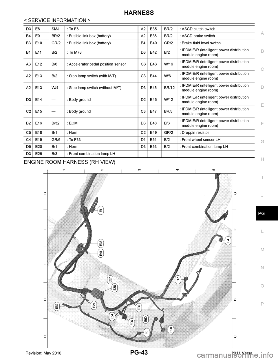
ENGINE ROOM HARNESS (RH VIEW)
D3 E8 SMJ : To F8 A2 E35 BR/2 : ASCD clutch switch
B4 E9 BR/2 : Fusible link box (battery) A2 E36 BR/2 : ASCD brake switch
B3 E10 GR/2 : Fusible link box (battery) B4 E40 GR/2 : Brake fluid level switch
B1 E11 B/2 : To M78 D3 E42 B/2: IPDM E/R (intelligent power distribution
module engine room)
A3 E12 B/6 : Accelerator pedal position sensor C3 E43 W/16 : IPDM E/R (intelligent power distribution
module engine room)
A2 E13 B/2 : Stop lamp switch (with M/T) C3 E44 W/6: IPDM E/R (intelligent power distribution
module engine room)
A2 E13 W/4 : Stop lamp switch (without M/T) D3 E45 BR/12: IPDM E/R (intelligent power distribution
module engine room)
D3 E14 — : Body ground D2 E46 W/12: IPDM E/R (intelligent power distribution
module engine room)
C2 E15 — : Body ground C3 E47 BR/8: IPDM E/R (intelligent power distribution
module engine room)
B2 E16 B/32 : ECM D3 E48 B/6: IPDM E/R (intelligent power distribution
module engine room)
C5 E18 B/1 : Horn C2 E49 GR/2 : Droppin resistor
C4 E19 GR/6 : To F33 D1 E51 B/2 : Front wheel sensor LH
D5 E20 B/1 : Horn D3 E53 B/2 : Front combination lamp LH
D3 E25 B/3 : Front combination lamp LH
Revision: May 2010 2011 Versa
Page 3478 of 3787

PG-58
< SERVICE INFORMATION >
HARNESS
Wiring Diagram Codes (Cell Codes)
INFOID:0000000005928356
Use the chart below to find out what each wiring diagram code stands for.
Refer to the wiring diagram code in the alphabetical index to find the location (page number) of each wiring
diagram.
D4 D406 W/2 : Back door request switch C2 D413 B/1 : Rear window defogger (-)
E2 D407 W/2 : High mounted stop lamp
Code Section Wiring Diagram Name
ABS BRC Anti-lock Brake System
A/C,M MTC Manual Air Conditioner
APPS1 EC Accelerator Pedal Position Sensor
A/F EC Air Fuel Ratio Sensor 1
A/FH EC Air Fuel Ratio Sensor 1 Heater
APPS2 EC Accelerator Pedal Position Sensor
APPS3 EC Accelerator Pedal Position Sensor
ASC/BS EC ASCD Brake Switch
ASC/SW EC ASCD Steering Switch
ASCBOF EC ASCD Brake Switch
ASCIND EC ASCD Indicator
AT/IND DI A/T Indicator Lamp
AUDIO AV Audio
BACK/L LT Back-up Lamp
BA/FTS AT A/T Fluid Temperature Sensor and TCM Power Supply
B/DOOR BL Back Door Opener
BRK/SW EC Brake Switch
CAN AT CAN Communication Line
CAN CVT CAN Communication Line
CAN EC CAN Communication Line
CAN LAN CAN System
CHARGE SC Charging System
CHIME DI Warning Chime
COOL/F EC Cooling Fan Control
COMBSW LT Combination Switch
COMM AV Audio Visual Communication System
CVTIND DI CVT Indicator Lamp
D/LOCK BL Power Door Lock
DEF GW Rear Window Defogger
DTRL LT Headlamp - With Daytime Light System
ECTS EC Engine Coolant Temperature Sensor
ENGSS AT Engine Speed Signal
EPS STC Electronic Controlled Power Steering
ETC1 EC Electric Throttle Control Function
ETC2 EC Throttle Control Motor Relay
ETC3 EC Throttle Control Motor
F/FOG LT Front Fog Lamp
F/PUMP EC Fuel Pump
FTS AT A/T Fluid Temperature Sensor
FTS CVT CVT Fluid Temperature Sensor Circuit
FTTS EC Fuel Tank Temperature Sensor
FUEL EC Fuel Ignition System Function
HEATER MTC Heater System
Revision: May 2010 2011 Versa
Page 3499 of 3787

NOISE, VIBRATION AND HARSHNESS (NVH) TROUBLESHOOTINGPS-5
< SERVICE INFORMATION >
C
DE
F
H I
J
K L
M A
B
PS
N
O P
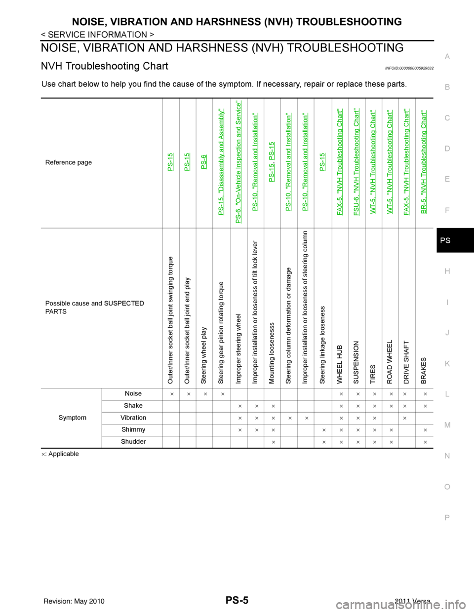
NOISE, VIBRATION AND HARSHN ESS (NVH) TROUBLESHOOTING
NVH Troubleshooting ChartINFOID:0000000005929632
Use chart below to help you find the cause of the symptom. If necessary, repair or replace these parts.
×: ApplicableReference page
PS-15PS-15PS-6
PS-15, "
Disassembly and Assembly
"
PS-6, "
On-Vehicle Inspection and Service
"
PS-10, "
Removal and Installation
"
PS-15
,
PS-15
PS-10, "
Removal and Installation
"
PS-10, "
Removal and Installation
"
PS-15
FAX-5, "
NVH Troubleshooting Chart
"
FSU-6, "
NVH Troubleshooting Chart
"
WT-5, "
NVH Troubleshooting Chart
"
WT-5, "
NVH Troubleshooting Chart
"
FAX-5, "
NVH Troubleshooting Chart
"
BR-5, "
NVH Troubleshooting Chart
"
Possible cause and SUSPECTED
PA R T S
Outer/Inner socket ball joint swinging torque
Outer/Inner socket ball joint end play
Steering wheel play
Steering gear pinion rotating torque
Improper steering wheel
Improper installation or looseness of tilt lock lever
Mounting loosenesss
Steering column deformation or damage
Improper installation or looseness of steering column
Steering linkage looseness
WHEEL HUB
SUSPENSION
TIRES
ROAD WHEEL
DRIVE SHAFT
BRAKES
Symptom Noise
××× × ××××× ×
Shake ×××××××× ×
Vibration ××××× ××× ×
Shimmy ×××× ×××× ×
Shudder ×× ×××× ×
Revision: May 2010 2011 Versa
Page 3500 of 3787

PS-6
< SERVICE INFORMATION >
STEERING WHEEL
STEERING WHEEL
On-Vehicle Inspection and ServiceINFOID:0000000006416714
CHECKING CONDITION OF INSTALLATION
• Check installation conditions of steering gear assembly, front suspension assembly, axle and steering col-
umn assembly.
• Check if movement exists when steering wheel is mo ved up and down, to the left and right and to the axial
direction.
• Check steering gear assembly bolts and nuts for looseness. Refer to PS-15, "
Removal and Installation".
CHECKING STEERING WHEEL PLAY
• Turn steering wheel so that front wheels come to the straight-ahead position. Start engine and lightly turn
steering wheel to the left and right until front wheels start to move. Measure steering wheel movement on the
outer circumference.
• When the measurement value is outside the standard val ue, check backlash for each joint of steering col-
umn assembly and installation condition of steering gear assembly.
CHECKING NEUTRAL POSITION STEERING WHEEL
• Make sure that steering gear assembly, steering column assembly and steering wheel are installed in the correct position.
• Perform neutral position inspection after wheel alignment. Refer to PS-2, "
Precaution for Supplemental
Restraint System (SRS) "AIR BAG" and "SEAT BELT PRE-TENSIONER"".
• Set vehicle to the straight-ahead position and c onfirm steering wheel is in the neutral position.
• Loosen outer socket lock nut and turn inner socket to left and right equally to make fine adjustments if steer-
ing wheel is not in the neutral position.
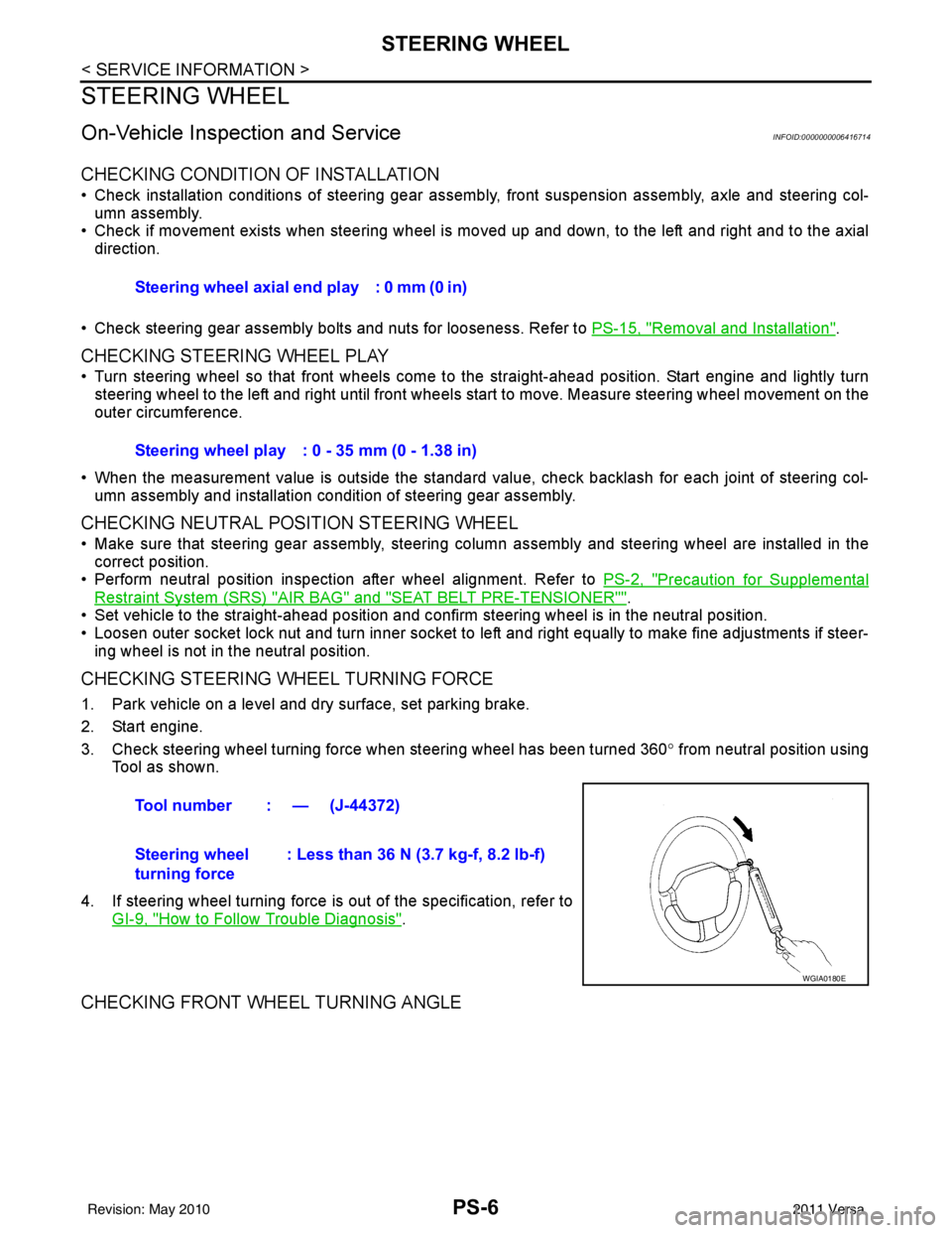
CHECKING STEERING WHEEL TURNING FORCE
1. Park vehicle on a level and dry surface, set parking brake.
2. Start engine.
3. Check steering wheel turning force when steering wheel has been turned 360 ° from neutral position using
Tool as shown.
4. If steering wheel turning force is out of the specification, refer to GI-9, "
How to Follow Trouble Diagnosis".
CHECKING FRONT WHEEL TURNING ANGLE
Steering wheel axial end play : 0 mm (0 in)
Steering wheel play : 0 - 35 mm (0 - 1.38 in)
Tool number : — (J-44372)
Steering wheel
turning force : Less than 36 N (3.7 kg-f, 8.2 lb-f)
WGIA0180E
Revision: May 2010
2011 Versa
Page 3520 of 3787
NOISE, VIBRATION AND HARSHNESS (NVH) TROUBLESHOOTINGRAX-5
< SERVICE INFORMATION >
CEF
G H
I
J
K L
M A
B
RAX
N
O P
NOISE, VIBRATION AND HARSHN ESS (NVH) TROUBLESHOOTING
NVH Troubleshooting ChartINFOID:0000000005928714
Use chart below to help you find the cause of the symptom. If necessary, repair or replace these parts.
×: Applicable Reference page
RAX-6—
RAX-6
RSU-5, "
NVH Troubleshooting Chart
"
WT-5, "
NVH Troubleshooting Chart
"
WT-5, "
NVH Troubleshooting Chart
"
BR-5, "
NVH Troubleshooting Chart
"
PS-5, "
NVH Troubleshooting Chart
"
Possible cause and SUSPECTED PARTS
Improper installation, looseness
Parts interference
Wheel bearing damage
REAR SUSPENSION
TIRES
ROAD WHEEL
BRAKES
STEERING
Symptom REAR AXLENoise
×× ×××××
Shake ×× ×××××
Vibration ×× ×× ×
Shimmy ×× ×××××
Shudder ××××××
Poor quality ride or handling ××××××
Revision: May 2010 2011 Versa