2011 NISSAN LATIO seat memory
[x] Cancel search: seat memoryPage 3654 of 3787

SRS-20
< SYMPTOM DIAGNOSIS >
TROUBLE DIAGNOSIS
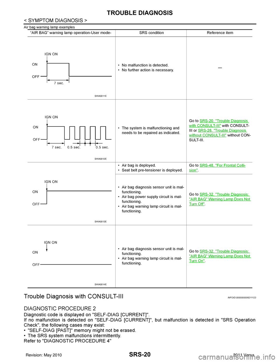
Air bag warning lamp examples
Trouble Diagnosis with CONSULT-IIIINFOID:0000000006211123
DIAGNOSTIC PROCEDURE 2
Diagnostic code is displayed on "SELF-DIAG [CURRENT]".
If no malfunction is detected on "SEL F-DIAG [CURRENT]", but malfunction is detected in "SRS Operation
Check", the following cases may exist:
• "SELF-DIAG [PAST]" memory might not be erased.
• The SRS system malfunctions intermittently.
Refer to "DIAGNOSTIC PROCEDURE 4"
“AIR BAG” warning lamp operation-User mode- SRS conditionReference item
• No malfunction is detected.
• No further action is necessary. —
• The system is malfunctioning and needs to be repaired as indicated. Go to
SRS-20, "
Trouble Diagnosis
with CONSULT-III" with CONSULT-
III or SRS-28, "
Trouble Diagnosis
without CONSULT-III" without CON-
SULT-III.
• Air bag is deployed.
• Seat belt pre-tensioner is deployed. Go to
SRS-48, "
For Frontal Colli-
sion".
• Air bag diagnosis sensor unit is mal- functioning.
• Air bag power supply circuit is mal- functioning.
• Air bag warning lamp circuit is mal- functioning. Go to
SRS-32, "
Trouble Diagnosis:
"AIR BAG" Warning Lamp Does Not
Turn Off".
• Air bag diagnosis sensor unit is mal- functioning.
• Air bag warning lamp circuit is mal- functioning. Go to
SRS-32, "
Trouble Diagnosis:
"AIR BAG" Warning Lamp Does Not
Turn On".
SHIA0011E
SHIA0012E
SHIA0013E
SHIA0014E
Revision: May 2010 2011 Versa
Page 3655 of 3787
![NISSAN LATIO 2011 Service Repair Manual TROUBLE DIAGNOSISSRS-21
< SYMPTOM DIAGNOSIS >
C
DE
F
G
I
J
K L
M A
B
SRS
N
O P
CONSULT-III Diagnostic Code
Chart ("SELF-DIAG [CURRENT]")
Diagnostic item Explanation Repair order
Recheck SRS at each r NISSAN LATIO 2011 Service Repair Manual TROUBLE DIAGNOSISSRS-21
< SYMPTOM DIAGNOSIS >
C
DE
F
G
I
J
K L
M A
B
SRS
N
O P
CONSULT-III Diagnostic Code
Chart ("SELF-DIAG [CURRENT]")
Diagnostic item Explanation Repair order
Recheck SRS at each r](/manual-img/5/57357/w960_57357-3654.png)
TROUBLE DIAGNOSISSRS-21
< SYMPTOM DIAGNOSIS >
C
DE
F
G
I
J
K L
M A
B
SRS
N
O P
CONSULT-III Diagnostic Code
Chart ("SELF-DIAG [CURRENT]")
Diagnostic item Explanation Repair order
Recheck SRS at each replacement
NO DTC IS DETECTED Malfunction is indicat-
ed by the “AIR BAG”
warning lamp in User
mode.Low battery voltage (Less than 9V) 1. Go to
SC-5, "
How to Handle Bat-
tery".
2. Go to "DIAGNOSTIC PROCE-
DURE 3" .
“SELF-DIAG [PAST]” memory might
not be erased. Go to "DIAGNOSTIC PROCEDURE 4"
.
Intermittent malfunction has been
detected in the past. Go to "DIAGNOSTIC PROCEDURE 5"
.
No malfunction is detected in User mode. —
DRIVER AIRBAG MODULE [OPEN]
[B1049] or [B1054] Driver air bag module circuit is open (including the spiral ca-
ble).
1. Visually check the wiring harness
connection.
2. Replace the harness if it has visi- ble damage.
3. Replace driver air bag module.
4. Replace the spiral cable.
5. Replace the air bag diagnosis sensor unit.
6. Replace the related harness.
DRIVER AIRBAG MODULE
[VB-SHORT]
[B1050] or [B1055] Driver air bag module circuit is shorted to some power supply
circuit (including the spiral cable).
DRIVER AIRBAG MODULE [GND-SHORT]
[B1051] or [B1056] Driver air bag module circuit is shorted to ground (including
the spiral cable).
DRIVER AIRBAG MODULE [SHORT]
[B1052] or [B1057] Driver air bag module circuits are shorted to each other.
ASSIST A/B MODULE [OPEN]
[B1065] or [B1070] Front passenger air bag module circuit is open.
1. Visually check the wiring harness
connection.
2. Replace the harness if it has visi- ble damage.
3. Replace front passenger air bag
module.
4. Replace the air bag diagnosis sensor unit.
5. Replace the related harness.
ASSIST A/B MODULE
[VB-SHORT]
[B1066] or [B1071] Front passenger air bag module circuit is shorted to some
power supply circuit.
ASSIST A/B MODULE [GND-SHORT]
[B1067] or [B1072] Front passenger air bag module circuit is shorted to ground.
ASSIST A/B MODULE [SHORT]
[B1068] or [B1073] Front passenger air bag module circuits are shorted to each
other.
CRASH ZONE SEN [UNIT FAIL]
[B1033] or [B1034]
CRASH ZONE SEN [COMM FAIL][B1035] Crash zone sensor
1. Visually check the wiring harness
connection.
2. Replace the harness if it has visi- ble damage.
3. Replace the crash zone sensor.
4. Replace the air bag diagnosis sensor unit.
5. Replace the related harness.
SIDE MODULE LH [OPEN][B1134] Front LH side air bag module circuit is open.
1. Visually check the wiring harness
connection.
2. Replace the harness if it has visi-
ble damage.
3. Replace front LH seat back as- sembly (front LH side air bag
module).
4. Replace the air bag diagnosis sensor unit.
5. Replace the related harness.
SIDE MODULE LH
[VB-SHORT][B1135] Front LH side air bag module circuit is shorted to some power
supply circuit.
SIDE MODULE LH [GND-SHORT]
[B1136] Front LH side air bag module circuit is shorted to ground.
SIDE MODULE LH [SHORT][B 11
37] Front LH side air bag module circuits are shorted to each oth-
er.
Revision: May 2010
2011 Versa
Page 3658 of 3787

SRS-24
< SYMPTOM DIAGNOSIS >
TROUBLE DIAGNOSIS
NOTE:
Follow the procedures in numerical order when performing repairs. Confirm whether the repair has been suc-
cessful using air bag warning lamp or CONSULT-III after each repair. If malfunction is still observed, proceed
to the next step. When malfunction has been elimi nated, further repair work is not required.
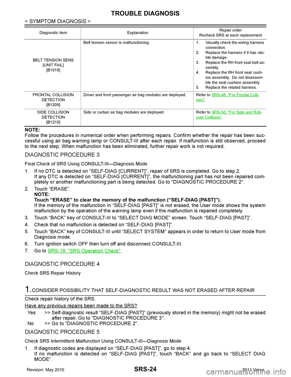
DIAGNOSTIC PROCEDURE 3
Final Check of SRS Using CONSULT-III—Diagnosis Mode
1. If no DTC is detected on “SELF-DIAG [CURRENT]”, repair of SRS is completed. Go to step 2.
If any DTC is detected on “SELF-DIAG [CURRENT]” , the malfunctioning part has not been repaired com-
pletely or another malfunctioning part is being detected. Go to "DIAGNOSTIC PROCEDURE 2".
2. Touch “ERASE”. NOTE:
Touch “ERASE” to clear the memory of the malfunction (“SELF-DIAG [PAST]”).
If the memory of the malfunction in “SELF-DIAG [P AST]” is not erased, the User mode shows the system
malfunction by the operation of the warning lamp even if the malfunction is repaired completely.
3. Touch “BACK” key of CONSULT-III to “SELECT DIAG MODE” screen. Touch “SELF-DIAG [PAST]”.
4. Check that no malfunction is detected on “SELF-DIAG [PAST]”.
5. Touch “BACK” key of CONSULT-III until “SELECT SY STEM” appears in order to return to User mode from
Diagnosis mode.
6. Turn ignition switch OFF then turn off and disconnect CONSULT-III.
7. Go to SRS-19, "
SRS Operation Check".
DIAGNOSTIC PROCEDURE 4
Check SRS Repair History
1.CONSIDER POSSIBILITY THAT SELF-DIAGNOSTIC RESULT WAS NOT ERASED AFTER REPAIR
Check repair history of the SRS.
Have any previous repairs been made to the SRS?
Yes >> Self-diagnostic result “SELF-DIAG [PAST]” (pre viously stored in the memory) might not be erased
after repair. Go to "DIAGNOSTIC PROCEDURE 3".
No >> Go to "DIAGNOSTIC PROCEDURE 2".
DIAGNOSTIC PROCEDURE 5
Check SRS Intermittent Malfuncti on Using CONSULT-III—Diagnosis Mode
1. If diagnostic codes are displayed on “SELF-DIAG [PAST]”, go to step 4.
If no malfunction is detected on “SELF-DIAG [PAS T]”, touch “BACK” and go back to “SELECT DIAG
MODE”.
BELT TENSION SENS
[UNIT FAIL]
[B1019] Belt tension sensor is malfunctioning.
1. Visually check the wiring harness
connection.
2. Replace the harness if it has visi- ble damage.
3. Replace the RH front seat belt as- sembly.
4. Replace the RH front seat cush-
ion assembly. Do not disassem-
ble the seat cushion assembly.
5. Replace the related harness.
FRONTAL COLLISION DETECTION[B1209] Driver and front passenger air bag modules are deployed. Refer to
SRS-48, "
For Frontal Colli-
sion".
SIDE COLLISION DETECTION
[B1210] Side or curtain air bag modules are deployed.
Refer to SRS-50, "
For Side and Roll-
over Collision".
Diagnostic item
Explanation Repair order
Recheck SRS at each replacement
Revision: May 2010 2011 Versa