2011 NISSAN LATIO charging
[x] Cancel search: chargingPage 1 of 3787

-1
QUICK REFERENCE INDEX
AGENERAL INFORMATIONGIGeneral Information
BENGINEEMEngine Mechanical
LUEngine Lubrication System
COEngine Cooling System
ECEngine Control System
FLFuel System
EXExhaust System
ACCAccelerator Control System
CTRANSMISSION/
TRANSAXLECLClutch System
MTManual Transaxle
ATAutomatic Transaxle
CVTCVT
DDRIVELINE/AXLEFAXFront Axle
RAXRear Axle
ESUSPENSIONFSUFront Suspension
RSURear Suspension
WTRoad Wheels & Tires
FBRAKESBRBrake System
PBParking Brake System
BRCBrake Control System
GSTEERINGPSPower Steering System
STCSteering Control System
HRESTRAINTSSBSeat Belts
SRSSupplemental Restraint System (SRS)
IBODYBLBody, Lock & Security System
GWGlasses, Window System & Mirrors
RFRoof
EIExterior & Interior
IPInstrument Panel
SESeat
JAIR CONDITIONERMTCManual Air Conditioner
KELECTRICALSCStarting & Charging System
LTLighting System
DIDriver Information System
WWWiper, Washer & Horn
BCSBody Control System
LANLAN System
AVAudio Visual, Navigation & Telephone System
ACSAuto Cruise Control System
PGPower Supply, Ground & Circuit Elements
LMAINTENANCEMAMaintenance
Edition: May 2010
Revision: May 2010
Publication No. SM1E-1C11U0
B
D
© 2010 NISSAN NORTH AMERICA, INC.
All rights reserved. No part of this Service Manual may be reproduced or stored in a retrieval system, or transmitted in any
form, or by any means, electronic, mechanical, photo-copying, recording or otherwise, without the prior written permission
of Nissan North America Inc.
A
C
E
F
G
H
I
J
K
L
M
Page 34 of 3787

A/T FLUIDAT-17
< SERVICE INFORMATION >
DE
F
G H
I
J
K L
M A
B
AT
N
O P
A/T FLUID
Checking A/T FluidINFOID:0000000005928070
1. Warm up engine.
2. Check for A/T fluid leakage.
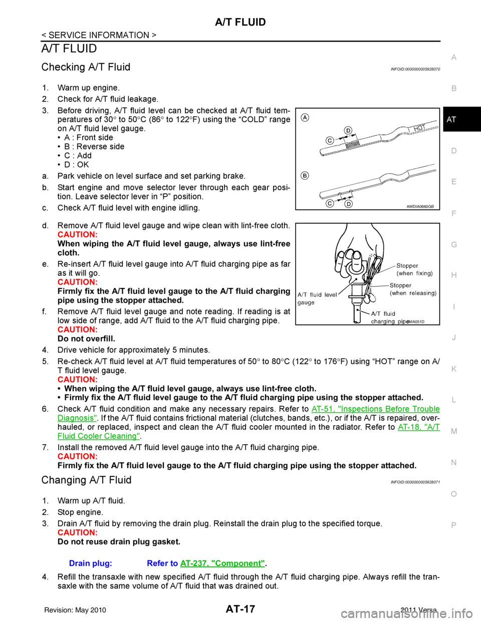
3. Before driving, A/T fluid level can be checked at A/T fluid tem- peratures of 30° to 50°C (86° to 122° F) using the “COLD” range
on A/T fluid level gauge.
• A : Front side
• B : Reverse side
•C : Add
• D : OK
a. Park vehicle on level surface and set parking brake.
b. Start engine and move selector lever through each gear posi- tion. Leave selector lever in “P” position.
c. Check A/T fluid level with engine idling.
d. Remove A/T fluid level gauge and wipe clean with lint-free cloth. CAUTION:
When wiping the A/T fluid l evel gauge, always use lint-free
cloth.
e. Re-insert A/T fluid level gauge into A/T fluid charging pipe as far as it will go.
CAUTION:
Firmly fix the A/T fluid level ga uge to the A/T fluid charging
pipe using the stopper attached.
f. Remove A/T fluid level gauge and note reading. If reading is at low side of range, add A/T fluid to the A/T fluid charging pipe.
CAUTION:
Do not overfill.
4. Drive vehicle for approximately 5 minutes.
5. Re-check A/T fluid level at A/T fluid temperatures of 50° to 80 °C (122° to 176°F) using “HOT” range on A/
T fluid level gauge.
CAUTION:
• When wiping the A/T fluid level gauge, always use lint-free cloth.
• Firmly fix the A/T fluid level ga uge to the A/T fluid charging pipe using the stopper attached.
6. Check A/T fluid condition and make any necessary repairs. Refer to AT-51, "
Inspections Before Trouble
Diagnosis". If the A/T fluid contains frictional material (clutches, bands, etc.), or if the A/T is repaired, over-
hauled, or replaced, inspect and clean the A/T fluid cooler mounted in the radiator. Refer to AT-18, "
A/T
Fluid Cooler Cleaning".
7. Install the removed A/T fluid level gauge into the A/T fluid charging pipe. CAUTION:
Firmly fix the A/T fluid level gaug e to the A/T fluid charging pipe using the stopper attached.
Changing A/T FluidINFOID:0000000005928071
1. Warm up A/T fluid.
2. Stop engine.
3. Drain A/T fluid by removing the drain plug. Re install the drain plug to the specified torque.
CAUTION:
Do not reuse drain plug gasket.
4. Refill the transaxle with new specified A/T fluid through the A/T fluid charging pipe. Always refill the tran- saxle with the same volume of A/T fluid that was drained out.
AWDIA0660GB
SMA051D
Drain plug: Refer to AT-237, "Component".
Revision: May 2010 2011 Versa
Page 92 of 3787

TROUBLE DIAGNOSISAT-75
< SERVICE INFORMATION >
DE
F
G H
I
J
K L
M A
B
AT
N
O P
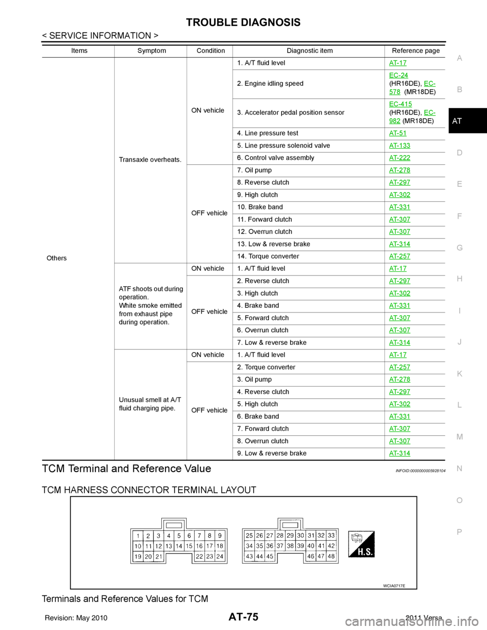
TCM Terminal and Reference ValueINFOID:0000000005928104
TCM HARNESS CONNECTOR TERMINAL LAYOUT
Terminals and Reference Values for TCM
Others Transaxle overheats.
ON vehicle
1. A/T fluid level
AT- 1 7
2. Engine idling speedEC-24
(HR16DE), EC-
578 (MR18DE)
3. Accelerator pedal position sensor EC-415
(HR16DE), EC-
982 (MR18DE)
4. Line pressure test AT- 5 1
5. Line pressure solenoid valveAT- 1 3 3
6. Control valve assemblyAT- 2 2 2
OFF vehicle7. Oil pump
AT- 2 7 8
8. Reverse clutchAT- 2 9 7
9. High clutchAT- 3 0 2
10. Brake bandAT- 3 3 1
11. Forward clutchAT- 3 0 7
12. Overrun clutchAT- 3 0 7
13. Low & reverse brakeAT- 3 1 4
14. Torque converterAT- 2 5 7
ATF shoots out during
operation.
White smoke emitted
from exhaust pipe
during operation.ON vehicle 1. A/T fluid level
AT- 1 7
OFF vehicle2. Reverse clutch
AT- 2 9 7
3. High clutchAT- 3 0 2
4. Brake bandAT- 3 3 1
5. Forward clutchAT- 3 0 7
6. Overrun clutchAT- 3 0 7
7. Low & reverse brakeAT- 3 1 4
Unusual smell at A/T
fluid charging pipe.ON vehicle 1. A/T fluid level
AT- 1 7
OFF vehicle2. Torque converter
AT- 2 5 7
3. Oil pumpAT- 2 7 8
4. Reverse clutchAT- 2 9 7
5. High clutchAT- 3 0 2
6. Brake bandAT- 3 3 1
7. Forward clutchAT- 3 0 7
8. Overrun clutchAT- 3 0 7
9. Low & reverse brakeAT- 3 1 4
ItemsSymptom Condition Diagnostic itemReference page
WCIA0717E
Revision: May 2010 2011 Versa
Page 250 of 3787

TRANSAXLE ASSEMBLYAT-233
< SERVICE INFORMATION >
DE
F
G H
I
J
K L
M A
B
AT
N
O P
TRANSAXLE ASSEMBLY
Removal and InstallationINFOID:0000000005928284
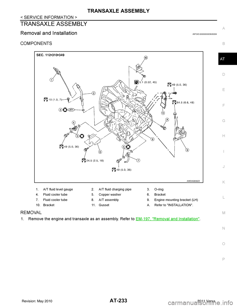
COMPONENTS
REMOVAL
1. Remove the engine and transaxle as an assembly. Refer to EM-197, "Removal and Installation".
1. A/T fluid level gauge2. A/T fluid charging pipe 3. O-ring
4. Fluid cooler tube 5. Copper washer 6. Bracket
7. Fluid cooler tube 8. A/T assembly9. Engine mounting bracket (LH)
10. Bracket 11. Gusset A. Refer to "INSTALLATION".
AWDIA0659ZZ
Revision: May 2010 2011 Versa
Page 251 of 3787

AT-234
< SERVICE INFORMATION >
TRANSAXLE ASSEMBLY
2. Disconnect the following connectors and remove the wire har-ness.
• Input speed sensor harness connector (1)
• Terminal cord assembly harness connector (2)
• Transmission range switch connector (3)
• output speed sensor harness connector (4)
3. Remove the four drive plate to torque converter bolts. NOTE:
Rotate the crankshaft clockwise as viewed from front of engine
for access to drive plate to torque converter bolts.
4. Put matching marks on the drive plate and torque converter. CAUTION:
For matching marks, use paint. Never dama ge the drive plate or torque converter.
5. Remove the transaxle to engine and engine to transaxle bolts.
6. Separate the transaxle from the engine. CAUTION:
Secure torque converter to prevent it from dropping.
7. If necessary, remove the following from the transaxle: • output speed sensor
• Input speed sensor
• Fluid cooler tubes (1) and copper washers
• A/T fluid level gauge (2) and charging pipe (3)
• Transmission range switch
• Air breather hose
• Engine mounting bracket (LH)
• Any necessary brackets
INSTALLATION
Installation is in the reverse order of removal.
CAUTION:
WCIA0647E
WCIA0616E
WCIA0648E
Revision: May 2010 2011 Versa
Page 1069 of 3787
![NISSAN LATIO 2011 Service Repair Manual CVT-14
< SERVICE INFORMATION >[RE0F08B]
CVT FLUID
CVT FLUID
Checking CVT FluidINFOID:0000000005928730
FLUID LEVEL CHECK
Fluid level should be checked with the fluid warmed up to 50
° to 80° C (122° NISSAN LATIO 2011 Service Repair Manual CVT-14
< SERVICE INFORMATION >[RE0F08B]
CVT FLUID
CVT FLUID
Checking CVT FluidINFOID:0000000005928730
FLUID LEVEL CHECK
Fluid level should be checked with the fluid warmed up to 50
° to 80° C (122°](/manual-img/5/57357/w960_57357-1068.png)
CVT-14
< SERVICE INFORMATION >[RE0F08B]
CVT FLUID
CVT FLUID
Checking CVT FluidINFOID:0000000005928730
FLUID LEVEL CHECK
Fluid level should be checked with the fluid warmed up to 50
° to 80° C (122° to 176°F).
1. Check for fluid leakage.
2. With the engine warmed up, drive the vehicle to warm up the CVT fluid. When ambient temperature is 20 °C (68° F), it takes
about 10 minutes for the CVT fluid to warm up to 50 ° to 80° C
(122° to 176 °F).
3. Park the vehicle on a level surface and set the parking brake.
4. With engine at idle, while depressing brake pedal, move the selector lever throughout the entire shift range and return it to
the “P” position.
5. Press the tab on the CVT fluid level gauge to release the lock and pull out the CVT fluid level gauge from the CVT fluid charg-
ing pipe.
6. Wipe fluid off the CVT fluid level gauge. Then rotate the CVT fluid level gauge 180 ° and re-insert it into the CVT charging pipe
as far as it will go.
CAUTION:
Always use lint free paper towels to wipe fluid off the CVT
fluid level gauge.
7. Remove the CVT fluid level gauge and check that the fluid level is within the specified range as shown. If the fluid level is at or
below the low side of the range, add the necessary specified
NISSAN CVT fluid through the CVT charging pipe.
CAUTION:
• Only use specified NISSAN CVT fluid.
• Do not overfill the CVT.
8. Install the CVT fluid level gauge to the CVT fluid charging pipe until it locks. CAUTION:
When CVT fluid level gauge is in stalled into the CVT fluid charging pipe, make sure that the CVT
fluid level gauge is securely locked in place.
SMA146B
SCIA1933E
SCIA1931E
Fluid grade: Refer to MA-14, "Fluids and Lubri-
cants".
SCIA1932E
Revision: May 2010 2011 Versa
Page 1070 of 3787
![NISSAN LATIO 2011 Service Repair Manual CVT FLUIDCVT-15
< SERVICE INFORMATION > [RE0F08B]
D
E
F
G H
I
J
K L
M A
B
CVT
N
O P
FLUID CONDITION CHECK
Changing CVT FluidINFOID:0000000005928731
1. Warm up CVT fluid by driving the vehicle for 10 m NISSAN LATIO 2011 Service Repair Manual CVT FLUIDCVT-15
< SERVICE INFORMATION > [RE0F08B]
D
E
F
G H
I
J
K L
M A
B
CVT
N
O P
FLUID CONDITION CHECK
Changing CVT FluidINFOID:0000000005928731
1. Warm up CVT fluid by driving the vehicle for 10 m](/manual-img/5/57357/w960_57357-1069.png)
CVT FLUIDCVT-15
< SERVICE INFORMATION > [RE0F08B]
D
E
F
G H
I
J
K L
M A
B
CVT
N
O P
FLUID CONDITION CHECK
Changing CVT FluidINFOID:0000000005928731
1. Warm up CVT fluid by driving the vehicle for 10 minutes.
• : Vehicle front
• Radiator (2)
• CVT fluid cooler hose [inlet side (3)]
• Transaxle assembly (4)
2. Drain CVT fluid from CVT fluid cooler hose [outlet side (1)] and refill with new specified NISSAN CVT fluid in the CVT fluid
charging pipe with the engine running at idle speed.
CAUTION:
Only use the specifi ed NISSAN CVT fluid.
3. Refill until new CVT fluid comes out from CVT fluid cooler hose [outlet side (1)]. NOTE:
About 30 to 50% extra fluid will be required for this procedure.
4. Check fluid level and condition. Refer to CVT-14, "
Checking CVT Fluid".
CAUTION:
Delete CVT fluid deterioration date with CONSULT-III after changing CVT fluid. Refer to CVT-48,
"CONSULT-III Function (TRANSMISSION)".
CVT Fluid Cooler CleaningINFOID:0000000005928732
Whenever a CVT is repaired, overhauled, or replaced, the CVT fluid cooler mounted in the radiator must be
inspected and cleaned.
Metal debris and friction material, if present, can be trapped or become deposit in the CVT fluid cooler. This
debris can contaminate the newly serviced CVT or, in severe cases, can block or restrict the flow of CVT fluid.
In either case, malfunction of the newly serviced CVT may occur.
Debris, if present, may deposit as CVT fluid enters the cool er inlet. It will be necessary to back flush the cooler
through the cooler outlet in order to flush out any built up debris.
CVT FLUID COOLER CLEANING PROCEDURE
1. Identify the CVT inlet and outlet fluid cooler hoses.
2. Position an oil pan under the inlet and outlet cooler hoses.
Fluid status Conceivable cause Required operation
Varnished (viscous
varnish state) Clutch, brake
scorchedReplace the CVT fluid and check the
CVT main unit and the vehicle for
malfunctions (wire harness, cooler
pipes, etc.)
Milky white or cloudy Water in the fluid Replace the CVT fluid and check for places where water is getting in.
Large amount of
metal powder mixed
in fluid Unusual wear of
sliding parts within
CVTReplace the CVT fluid and check for
improper operation of the CVT.
ATA0022D
Fluid capacity and grade: Refer to
MA-14, "Fluids
and Lubricants".SCIA6088E
Revision: May 2010 2011 Versa
Page 1235 of 3787
![NISSAN LATIO 2011 Service Repair Manual CVT-180
< SERVICE INFORMATION >[RE0F08B]
TRANSAXLE ASSEMBLY
TRANSAXLE ASSEMBLY
Removal and InstallationINFOID:0000000005928976
COMPONENTS
REMOVAL
WARNING:
Never remove the radiator cap when the engine NISSAN LATIO 2011 Service Repair Manual CVT-180
< SERVICE INFORMATION >[RE0F08B]
TRANSAXLE ASSEMBLY
TRANSAXLE ASSEMBLY
Removal and InstallationINFOID:0000000005928976
COMPONENTS
REMOVAL
WARNING:
Never remove the radiator cap when the engine](/manual-img/5/57357/w960_57357-1234.png)
CVT-180
< SERVICE INFORMATION >[RE0F08B]
TRANSAXLE ASSEMBLY
TRANSAXLE ASSEMBLY
Removal and InstallationINFOID:0000000005928976
COMPONENTS
REMOVAL
WARNING:
Never remove the radiator cap when the engine is hot. Serious burns coul
d occur from high pressure
coolant escaping from the radiator.
CAUTION:
• Perform this step engine is cold.
• When replacing TCM and transaxle assembly as a set, replace transaxle assembly first and then replace TCM. Refer to CVT-8, "
Service After Replacing TCM and Transaxle Assembly".
1. Remove the engine and transaxle as an assembly. Refer to EM-197, "
Removal and Installation".
1. CVT fluid level gauge2. CVT fluid charging pipe 3. O-ring
4. Copper washer 5. Fluid cooler tube6. Transaxle assembly
7. Engine mounting bracket (LH) 8. Air breather hose A. Refer to "INSTALLATION".
WCIA0614E
Revision: May 2010 2011 Versa