Page 361 of 3787
AT-344
< SERVICE INFORMATION >
ASSEMBLY
ASSEMBLY
Assembly (1)INFOID:0000000005928303
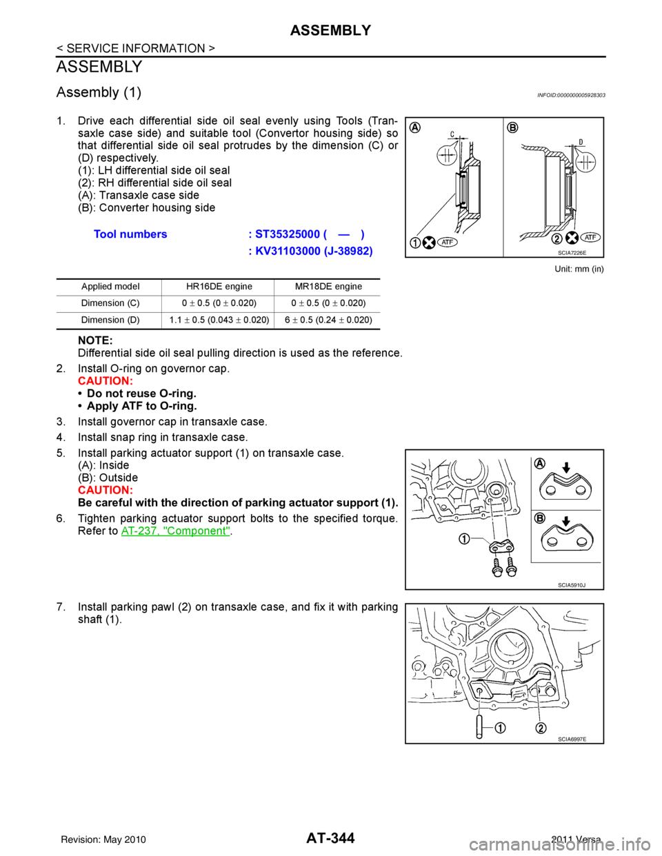
1. Drive each differential side oil seal evenly using Tools (Tran-saxle case side) and suitable tool (Convertor housing side) so
that differential side oil seal protrudes by the dimension (C) or
(D) respectively.
(1): LH differential side oil seal
(2): RH differential side oil seal
(A): Transaxle case side
(B): Converter housing side
Unit: mm (in)
NOTE:
Differential side oil seal pulling direction is used as the reference.
2. Install O-ring on governor cap. CAUTION:
• Do not reuse O-ring.
• Apply ATF to O-ring.
3. Install governor cap in transaxle case.
4. Install snap ring in transaxle case.
5. Install parking actuator support (1) on transaxle case. (A): Inside
(B): Outside
CAUTION:
Be careful with the direction of parking actuator support (1).
6. Tighten parking actuator support bolts to the specified torque. Refer to AT-237, "
Component".
7. Install parking pawl (2) on transaxle case, and fix it with parking shaft (1).Tool numbers
: ST35325000 ( — )
: KV31103000 (J-38982)
Applied model HR16DE engine MR18DE engine
Dimension (C) 0 ± 0.5 (0 ± 0.020) 0 ± 0.5 (0 ± 0.020)
Dimension (D) 1.1 ± 0.5 (0.043 ± 0.020) 6 ± 0.5 (0.24 ± 0.020)
SCIA7226E
SCIA5910J
SCIA6997E
Revision: May 2010 2011 Versa
Page 362 of 3787

ASSEMBLYAT-345
< SERVICE INFORMATION >
DE
F
G H
I
J
K L
M A
B
AT
N
O P
8. Install return spring (2) on parking shaft (3) and parking pawl (1) using a suitable tool.
Adjustment (1) (For HR16DE Engine Models)INFOID:0000000005928304
REDUCTION PINION GEAR BEARING PRELOAD
1. Select proper thickness of reduction pinion gear adjusting shim using the following procedures.
a. Place reduction pinion gear on transaxle case as shown.
b. Install idler gear bearing outer race on transaxle case.
c. Place idler gear bearing inner race on outer race.
d. Measure dimensions (B), (C) and (D), and calculate dimension (A).
• Measure dimension (B) between the end of reduction piniongear and the surface of transaxle case.
• Measure dimension (B) in at least two places, and take the
average.
SCIA6996E
SCIA3623E
(A) : Distance between the surface of idler gear
bearing inner race and th e adjusting shim mat-
ing surface of reduction pinion gear.
A = D − (B + C)
SCIA3624E
SCIA3625E
Revision: May 2010 2011 Versa
Page 366 of 3787
ASSEMBLYAT-349
< SERVICE INFORMATION >
DE
F
G H
I
J
K L
M A
B
AT
N
O P
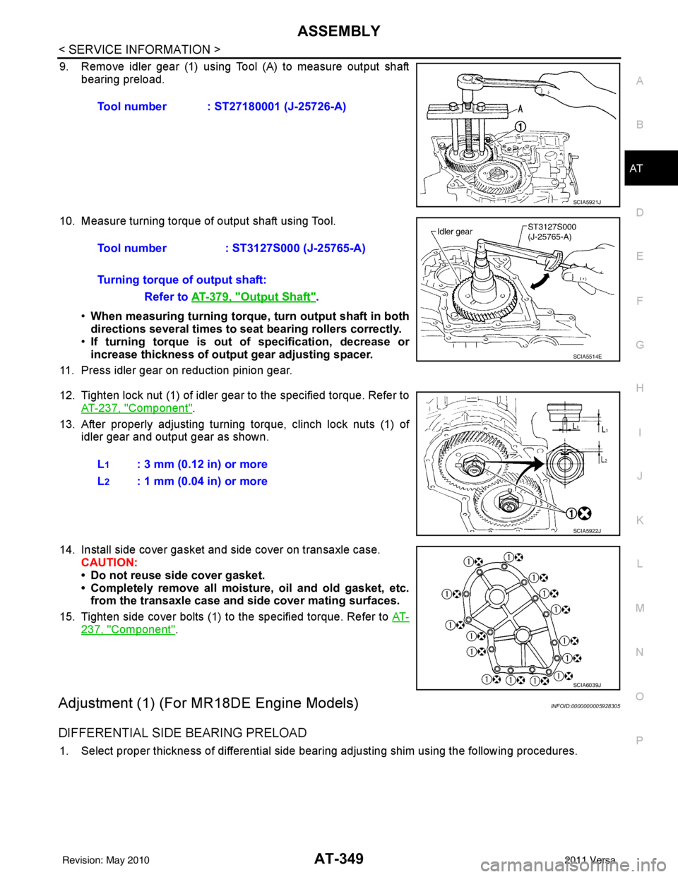
9. Remove idler gear (1) using Tool (A) to measure output shaft bearing preload.
10. Measure turning torque of output shaft using Tool. •When measuring turning torque , turn output shaft in both
directions several times to seat bearing rollers correctly.
• If turning torque is out of specification, decrease or
increase thickness of output gear adjusting spacer.
11. Press idler gear on reduction pinion gear.
12. Tighten lock nut (1) of idler gear to the specified torque. Refer to AT-237, "
Component".
13. After properly adjusting turning torque, clinch lock nuts (1) of idler gear and output gear as shown.
14. Install side cover gasket and side cover on transaxle case. CAUTION:
• Do not reuse side cover gasket.
• Completely remove all moistu re, oil and old gasket, etc.
from the transaxle case and side cover mating surfaces.
15. Tighten side cover bolts (1) to the specified torque. Refer to AT-
237, "Component".
Adjustment (1) (For MR18DE Engine Models)INFOID:0000000005928305
DIFFERENTIAL SIDE BEARING PRELOAD
1. Select proper thickness of differential side bearing adjusting shim using the following procedures.Tool number : ST27180001 (J-25726-A)
SCIA5921J
Tool number
: ST3127S000 (J-25765-A)
Turning torque of output shaft: Refer to AT-379, "
Output Shaft".
SCIA5514E
L1: 3 mm (0.12 in) or more
L
2: 1 mm (0.04 in) or more
SCIA5922J
SCIA6039J
Revision: May 2010 2011 Versa
Page 382 of 3787
ASSEMBLYAT-365
< SERVICE INFORMATION >
DE
F
G H
I
J
K L
M A
B
AT
N
O P
13. Adjust brake band.
a. Tighten anchor end pin to the specified torque.
b. Back off anchor end pin two and a half turns.
c. Tighten lock nut while holding anchor end pin. Refer to AT-237,
"Component".
14. Apply compressed air into oil holes of transaxle case and check operation of brake band.
15. Select proper thickness of differential side bear ing adjusting shim using the following procedures.
(HR16DE engine models)
• Measure differential side bearing end play, and calculat e the adjusting shim thickness so that the end
play is within the specifications. Anchor end pin bolt : 4.9 N·m (0.50 kg-m, 43 in-lb)
SAT394D
SAT395D
SAT396D
SAT397D
Differential side bearin
g end play : Refer to AT-379, "Total End
Play"
Revision: May 2010 2011 Versa
Page 383 of 3787
AT-366
< SERVICE INFORMATION >
ASSEMBLY
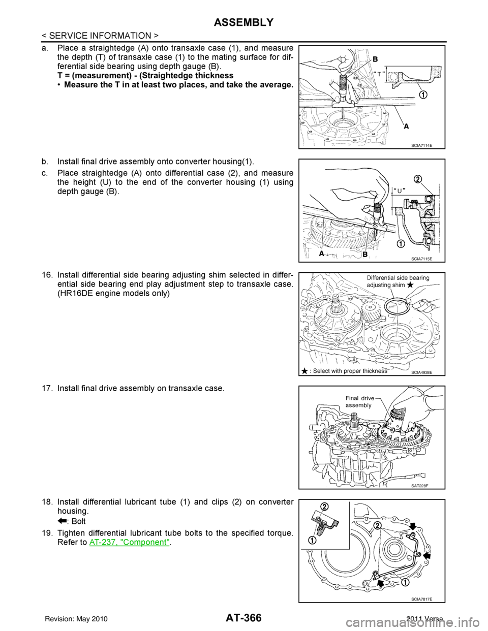
a. Place a straightedge (A) onto transaxle case (1), and measurethe depth (T) of transaxle case (1) to the mating surface for dif-
ferential side bearing using depth gauge (B).
T = (measurement) - (Straightedge thickness
•Measure the T in at least two places, and take the average.
b. Install final drive assembly onto converter housing(1).
c. Place straightedge (A) onto differential case (2), and measure the height (U) to the end of the converter housing (1) using
depth gauge (B).
16. Install differential side bearing adjusting shim selected in differ- ential side bearing end play adjustment step to transaxle case.
(HR16DE engine models only)
17. Install final drive assembly on transaxle case.
18. Install differential lubricant tube (1) and clips (2) on converter housing.
: Bolt
19. Tighten differential lubricant tube bolts to the specified torque. Refer to AT-237, "
Component".
SCIA7114E
SCIA7115E
SCIA4938E
SAT228F
SCIA7817E
Revision: May 2010 2011 Versa
Page 384 of 3787
ASSEMBLYAT-367
< SERVICE INFORMATION >
DE
F
G H
I
J
K L
M A
B
AT
N
O P
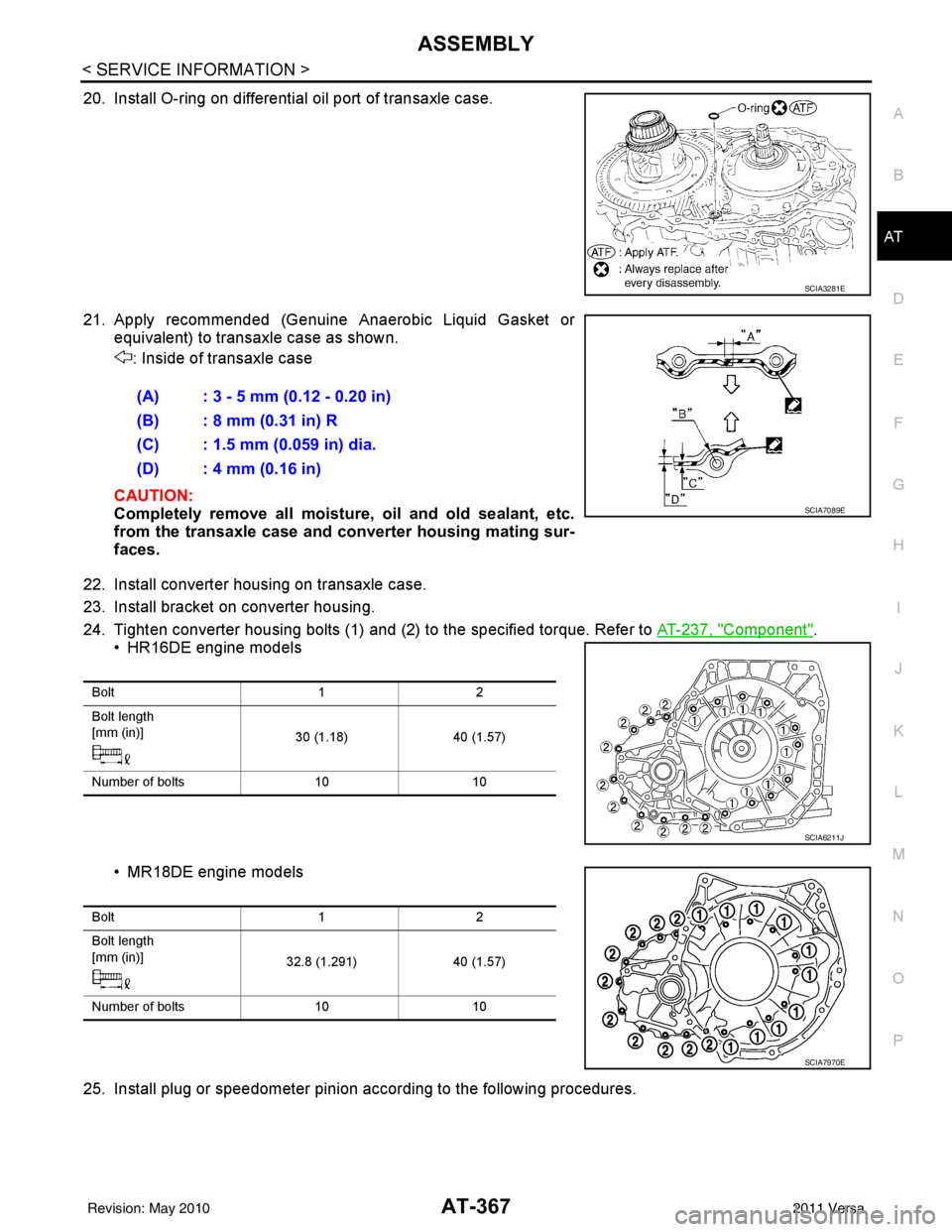
20. Install O-ring on differential oil port of transaxle case.
21. Apply recommended (Genuine Anaerobic Liquid Gasket or equivalent) to transaxle case as shown.
: Inside of transaxle case
CAUTION:
Completely remove all moisture, oil and old sealant, etc.
from the transaxle case and converter housing mating sur-
faces.
22. Install converter housing on transaxle case.
23. Install bracket on converter housing.
24. Tighten converter housing bolts (1) and (2) to the specified torque. Refer to AT-237, "
Component".
• HR16DE engine models
• MR18DE engine models
25. Install plug or speedometer pinion according to the following procedures.
SCIA3281E
(A) : 3 - 5 mm (0.12 - 0.20 in)
(B) : 8 mm (0.31 in) R
(C) : 1.5 mm (0.059 in) dia.
(D) : 4 mm (0.16 in)
SCIA7089E
Bolt 12
Bolt length
[mm (in)] 30 (1.18)40 (1.57)
Number of bolts 1010
SCIA6211J
Bolt 12
Bolt length
[mm (in)] 32.8 (1.291)40 (1.57)
Number of bolts 1010
SCIA7970E
Revision: May 2010 2011 Versa
Page 387 of 3787
AT-370
< SERVICE INFORMATION >
ASSEMBLY
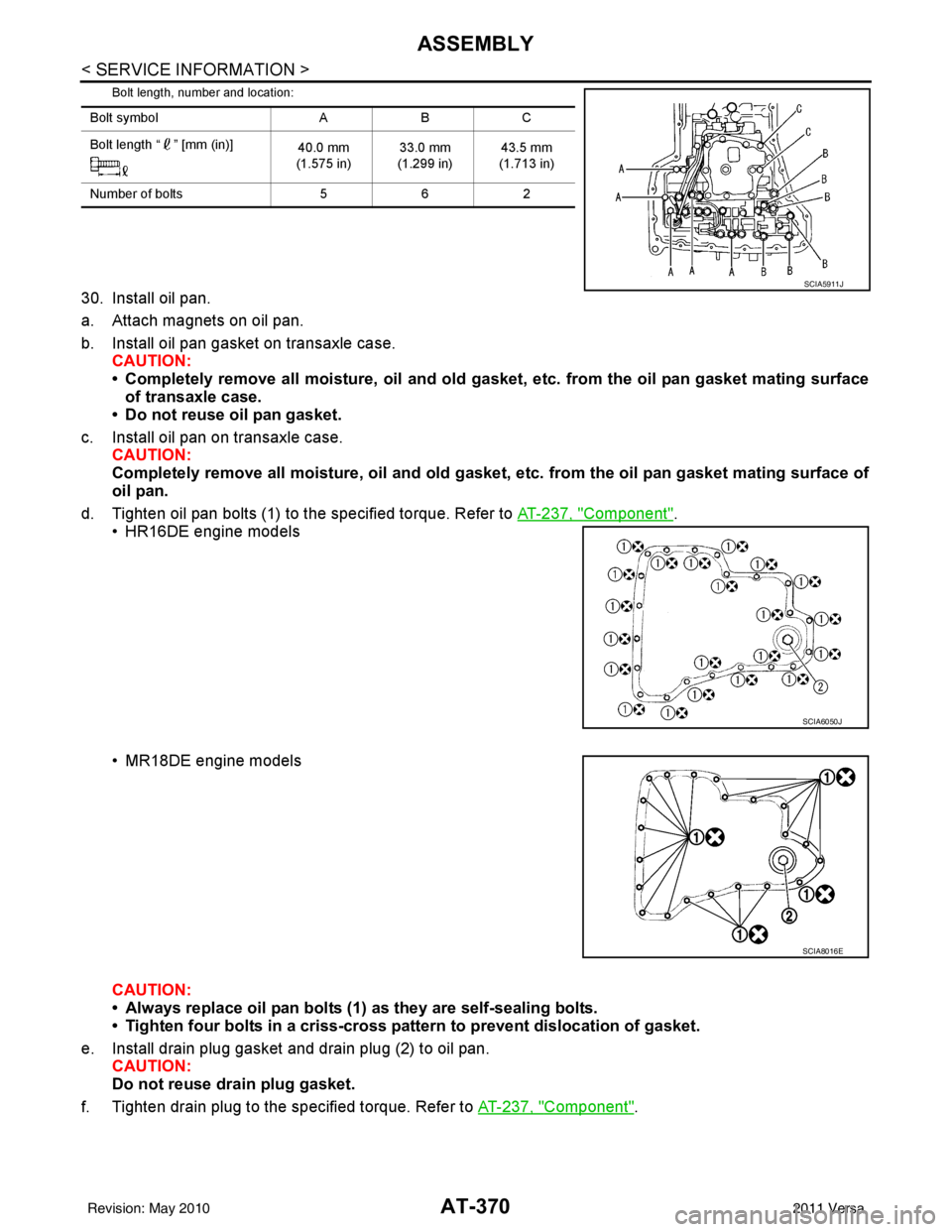
Bolt length, number and location:
30. Install oil pan.
a. Attach magnets on oil pan.
b. Install oil pan gasket on transaxle case.CAUTION:
• Completely remove all moisture, oil and old gasket , etc. from the oil pan gasket mating surface
of transaxle case.
• Do not reuse oil pan gasket.
c. Install oil pan on transaxle case. CAUTION:
Completely remove all moisture, oil and old gasket , etc. from the oil pan gasket mating surface of
oil pan.
d. Tighten oil pan bolts (1) to the specified torque. Refer to AT-237, "
Component".
• HR16DE engine models
• MR18DE engine models
CAUTION:
• Always replace oil pan bolts (1) as they are self-sealing bolts.
• Tighten four bolts in a criss-cross pattern to prevent dislocation of gasket.
e. Install drain plug gasket and drain plug (2) to oil pan. CAUTION:
Do not reuse drain plug gasket.
f. Tighten drain plug to the specified torque. Refer to AT-237, "
Component".
Bolt symbolABC
Bolt length “ ” [mm (in)] 40.0 mm
(1.575 in) 33.0 mm
(1.299 in) 43.5 mm
(1.713 in)
Number of bolts 562
SCIA5911J
SCIA6050J
SCIA8016E
Revision: May 2010 2011 Versa
Page 390 of 3787

SERVICE DATA AND SPECIFICATIONS (SDS)AT-373
< SERVICE INFORMATION >
DE
F
G H
I
J
K L
M A
B
AT
N
O P
SERVICE DATA AND SPECIFICATIONS (SDS)
General SpecificationINFOID:0000000005928309
*: Refer to MA-14.
Vehicle Speed at Which Gear Shifting OccursINFOID:0000000005928310
HR16DE engine models
MR18DE engine models
• At half throttle, the accelerator opening is 4/8 of the full opening.
Vehicle Speed at When Lock-up Occurs/ReleasesINFOID:0000000005928311
HR16DE engine models
MR18DE engine models
Engine HR16DEMR18DE
Automatic transaxle model RE4F03B
Automatic transaxle assembly Model code number 3CX3D, 3CX3E3CX0D
Transaxle gear ratio 1st
2.861
2nd 1.562
3rd 1.000
4th 0.697
Reverse 2.310
Final drive 4.072
Recommended fluid Genuine NISSAN Matic S ATF (Continental U.S. and Alaska) or
Canada NISSAN Automatic Transmission Fluid*
Fluid capacity [ (US qt, Imp qt)] 7.7 (8-1/8, 6-3/4)
7.9 (8-3/8, 7)
Throttle position Vehicle speed km/h (MPH)
D1 → D2D2 → D3D3 → D4D4 → D3D3 → D2D2 → D1
Full throttle 49 - 57
(31 - 35) 93 - 101
(58 - 62) 148 - 156
(92 - 96) 144 - 152
(90 - 94) 82 - 90
(51 - 55) 39 - 47
(25 - 29)
Half throttle 35 - 43
(22 - 26) 59 - 67
(37 - 41) 117 - 125
(73 - 77) 59 - 67
(37 - 41) 34 - 42
(22 - 26) 15 - 23
(10 - 14)
Throttle position Vehicle speed km/h (MPH)
D
1 → D2D2 → D3D3 → D4D4 → D3D3 → D2D2 → D1
Full throttle 51 - 59
(32 - 37) 97 - 105
(60 - 65) 154 - 162
(96 - 101) 150 - 158
(93 - 98) 87 - 95
(54 - 59) 40 - 48
(25 - 30)
Half throttle 34 - 42
(21 - 26) 62 - 70
(39 - 43) 124 - 132
(77 - 82) 69 - 77
(43 - 48) 36 - 44
(22 - 27) 19 - 27
(12 - 17)
Throttle position Selector lever position Vehicle speed km/h (MPH)
Lock-up ON Lock-up OFF
2.0/8 “D” position
73 - 81 (46 - 50) 49 - 57 (31 - 35)
“D” position (OD OFF) 86 - 94 (53 - 58) 82 - 90 (51 - 55)
Throttle position Selector lever position Vehicle speed km/h (MPH)
Lock-up ON Lock-up OFF
2.0/8 “D” position
86 - 94 (53 - 58) 59 - 67 (37 - 42)
“D” position (OD OFF) 86 - 94 (53 - 58) 83 - 91 (52 - 57)
Revision: May 2010 2011 Versa