2011 NISSAN LATIO change time
[x] Cancel search: change timePage 2 of 3787

-2
This manual contains maintenance and repair procedures for the
2011 NISSAN VERSA.
In order to assure your safety and the efficient functioning of the vehicle,
this manual should be read thoroughly. It is especially important that the
PRECAUTIONS in the GI section be completely understood before starting
any repair task.
All information in this manual is based on the latest product information
at the time of publication. The right is reserved to make changes in specifi-
cations and methods at any time without notice.
IMPORTANT SAFETY NOTICE
The proper performance of service is essential for both the safety of
the technician and the efficient functioning of the vehicle.
The service methods in this Service Manual are described in such a
manner that the service may be performed safely and accurately.
Service varies with the procedures used, the skills of the technician
and the tools and parts available. Accordingly, anyone using service
procedures, tools or parts which are not specifically recommended
by NISSAN must first be completely satisfied that neither personal
safety nor the vehicle’s safety will be jeopardized by the service
method selected.
Page 127 of 3787

AT-110
< SERVICE INFORMATION >
P0731 1GR INCORRECT RATIO
5. Accelerate vehicle to 20 to 25 km/h (12 to 16 MPH) under the following conditions and release the accel-erator pedal completely.
THROTTLE POSI: Less than 1.0/8 (at all times during step 4)
SLCT LVR POSI: “D” position
- Make sure that “GEAR” shows “2” after releasing pedal.
6. Depress accelerator pedal to WOT (more than 7.0/8 of “THROTTLE POSI”) quickly from a speed of 20 to
25 km/h (12 to 16 MPH) until “TESTING” changes to “STOP VEHICLE” or “COMPLETED”. (It will take
approximately 3 seconds.)
If the check result NG appears on CONSULT-III screen, go to AT-110, "
Diagnosis Procedure".
If “STOP VEHICLE” appears on CONSULT- III screen, go to the following step.
- Make sure that “GEAR” shows “1” wh en depressing accelerator pedal to WOT.
- If “TESTING” does not appear on CONSULT-III fo r a long time, select “SELF-DIAG RESULTS” for
“TRANSMISSION”. In case a DTC other than “P0731 1GR INCORRECT RATIO” is shown, refer to
AT-77, "
CONSULT-III Funct ion (TRANSMISSION)".
7. Stop vehicle.
8. Follow the instruction displayed. (Check for normal shifting referring to the table below.)
9. Make sure that “OK” is displayed. (If “NG” is displayed, refer to “Diagnostic Procedure”.)
Refer to AT-110, "
Diagnosis Procedure".
Refer to AT-64, "
Vehicle Speed at Which Gear Shifting Occurs".
WITH GST
Follow the procedure “WITH CONSULT-III”.
Diagnosis ProcedureINFOID:0000000005928147
1.CHECK VALVE RESISTANCE
1. Remove control valve assembly. Refer to AT-222, "
Control Valve Assembly and Accumulators".
- Shift solenoid valve A
- Shift solenoid valve B
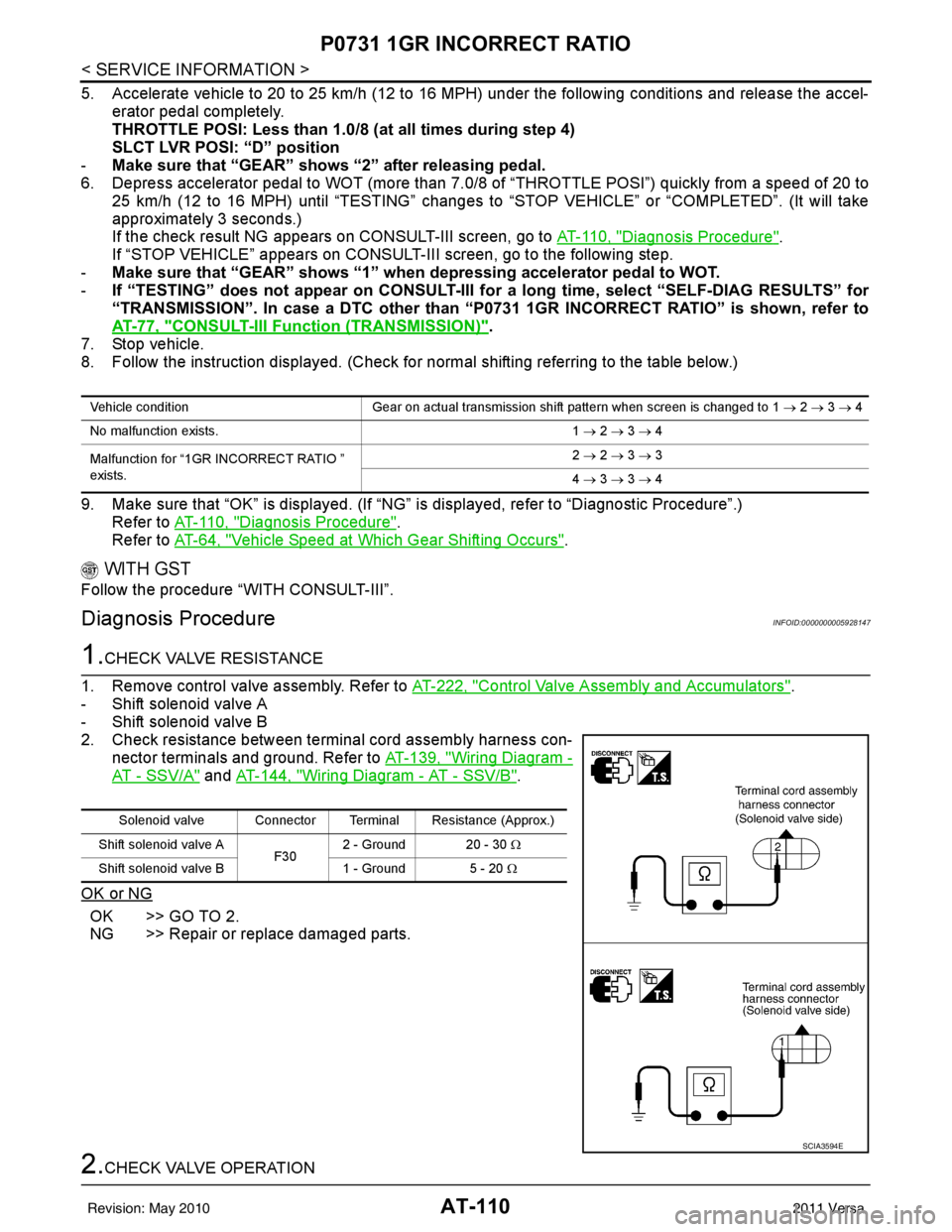
2. Check resistance between terminal cord assembly harness con- nector terminals and ground. Refer to AT-139, "
Wiring Diagram -
AT - SSV/A" and AT-144, "Wiring Diagram - AT - SSV/B".
OK or NG
OK >> GO TO 2.
NG >> Repair or replace damaged parts.
2.CHECK VALVE OPERATION
Vehicle condition Gear on actual transmission shift pattern when screen is changed to 1 → 2 → 3 → 4
No malfunction exists. 1 → 2 → 3 → 4
Malfunction for “1GR INCORRECT RATIO ”
exists. 2
→ 2 → 3 → 3
4 → 3 → 3 → 4
Solenoid valve Connector Terminal Resistance (Approx.)
Shift solenoid valve A F302 - Ground 20 - 30
Ω
Shift solenoid valve B 1 - Ground 5 - 20 Ω
SCIA3594E
Revision: May 2010 2011 Versa
Page 130 of 3787

P0732 2GR INCORRECT RATIOAT-113
< SERVICE INFORMATION >
DE
F
G H
I
J
K L
M A
B
AT
N
O P
- Make sure that “GEAR” shows “3” or “4” after releasing pedal.
6. Depress accelerator pedal to WOT (more than 7.0/8 of “THROTTLE POSI”) quickly from a speed of 45 to 50 km/h (28 to 31 MPH) until “TESTING” changes to “STOP VEHICLE” or “COMPLETE”. (It will take
approximately 3 seconds.)
If the check result NG appears on CONSULT-III screen, go to AT-113, "
Diagnosis Procedure".
If “STOP VEHICLE” appears on CONSULT-III screen, go to following step.
- Make sure that “GEAR” shows “2” when depressing accelerator pedal to WOT.
- If “TESTING” does not appear on CONSULT-III fo r a long time, select “SELF-DIAG RESULTS” for
“TRANSMISSION”. In case a DTC other than “P0732 2GR INCORRECT RATIO” is shown, refer to
AT-77, "
CONSULT-III Function (TRANSMISSION)".
7. Stop vehicle.
8. Follow the instruction displayed. (Check for normal shifting referring to the table below.)
9. Make sure that “OK” is disp layed. (If “NG” is displayed, refer to “Diagnostic Procedure”.)
Refer to AT-113, "
Diagnosis Procedure".
Refer to AT-64, "
Vehicle Speed at Which Gear Shifting Occurs".
WITH GST
Follow the procedure “WITH CONSULT-III”.
Diagnosis ProcedureINFOID:0000000005928152
1.CHECK VALVE RESISTANCE
1. Remove control valve assembly. Refer to AT-222, "
Control Valve Assembly and Accumulators".
- Shift solenoid valve B
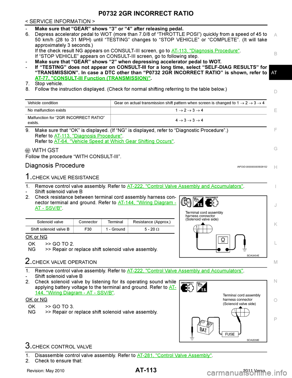
2. Check resistance between terminal cord assembly harness con- nector terminal and ground. Refer to AT-144, "
Wiring Diagram -
AT - SSV/B".
OK or NG
OK >> GO TO 2.
NG >> Repair or replace shift solenoid valve assembly.
2.CHECK VALVE OPERATION
1. Remove control valve assembly. Refer to AT-222, "
Control Valve Assembly and Accumulators".
- Shift solenoid valve B
2. Check solenoid valve by listening for its operating sound while applying battery voltage to the terminal and ground. Refer to AT-
144, "Wiring Diagram - AT - SSV/B".
OK or NG
OK >> GO TO 3.
NG >> Repair or replace shift solenoid valve assembly.
3.CHECK CONTROL VALVE
1. Disassemble control valve assembly. Refer to AT-281, "
Control Valve Assembly".
2. Check to ensure that:
Vehicle condition Gear on actual transmission shift pattern when screen is changed to 1 → 2 → 3 → 4
No malfunction exists 1 → 2 → 3 → 4
Malfunction for “2GR INCORRECT RATIO”
exists. 4
→ 3 → 3 → 4
Solenoid valve Connector Terminal Resistance (Approx.)
Shift solenoid valve B F30 1 - Ground 5 - 20 Ω
SCIA3454E
SCIA2058E
Revision: May 2010 2011 Versa
Page 133 of 3787

AT-116
< SERVICE INFORMATION >
P0733 3GR INCORRECT RATIO
-Make sure that “GEAR” shows “4” after releasing pedal.
6. Depress accelerator pedal steadily with 3.5/8 - 4.5/8 of “THROTTLE POSI” from a speed of 60 to 75 km/h (37 to 47 MPH) until “TESTING” changes to “STOP VEHICLE” or “COMPLETED”. (It will take approxi-
mately 3 seconds.)
If the check result NG appears on CONSULT-III screen, go to AT-116, "
Diagnosis Procedure".
If “STOP VEHICLE” appears on CONSUL T-III screen, go to following step.
- Make sure that “GEAR” shows “3” when depressing accelerator pedal with 3.5/8 - 4.5/8 of
“THROTTLE POSI”.
- If “TESTING” does not appear on CONSULT-III fo r a long time, select “SELF-DIAG RESULTS” for
“TRANSMISSION”. In case a DTC other than “P0733 3GR INCORRECT RATIO” is shown, refer to
AT-77, "
CONSULT-III Funct ion (TRANSMISSION)".
7. Stop vehicle.
8. Follow the instruction displayed. (Check for normal shifting referring to the table below.)
9. Make sure that “OK” is displayed. (If “NG” is displayed, refer to “Diagnostic Procedure”.)
Refer to AT-116, "
Diagnosis Procedure".
Refer to AT-64, "
Vehicle Speed at Which Gear Shifting Occurs".
WITH GST
Follow the procedure “WITH CONSULT-III”.
Diagnosis ProcedureINFOID:0000000005928157
1.CHECK VALVE RESISTANCE
1. Remove control valve assembly. Refer to AT-222, "
Control Valve Assembly and Accumulators".
- Shift solenoid valve A
- Shift solenoid valve B
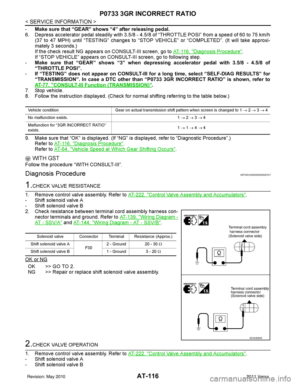
2. Check resistance between terminal cord assembly harness con- nector terminals and ground. Refer to AT-139, "
Wiring Diagram -
AT - SSV/A" and AT-144, "Wiring Diagram - AT - SSV/B".
OK or NG
OK >> GO TO 2.
NG >> Repair or replace shift solenoid valve assembly.
2.CHECK VALVE OPERATION
1. Remove control valve assembly. Refer to AT-222, "
Control Valve Assembly and Accumulators".
- Shift solenoid valve A
- Shift solenoid valve B
Vehicle condition Gear on actual transmission shift pattern when screen is changed to 1 → 2 → 3 → 4
No malfunction exists. 1 → 2 → 3 → 4
Malfunction for “3GR INCORRECT RATIO”
exists. 1
→ 1 → 4 → 4
Solenoid valve Connector Terminal Resistance (Approx.)
Shift solenoid valve A F302 - Ground 20 - 30
Ω
Shift solenoid valve B 1 - Ground 5 - 20 Ω
SCIA3594E
Revision: May 2010 2011 Versa
Page 136 of 3787

P0734 4GR INCORRECT RATIOAT-119
< SERVICE INFORMATION >
DE
F
G H
I
J
K L
M A
B
AT
N
O P
WITH CONSULT-III
1. Start engine and select “DATA MONITOR” m ode for “TRANSMISSION” with CONSULT-III.
2. Touch “START”.
3. Make sure that output voltage of A/T fluid temperature sensor is within the range below. FLUID TEMP SE: 0.4 - 1.5 V
If out of range, drive the vehicle to decrease the vo ltage (warm up the fluid) or stop engine to increase the
voltage (cool down the fluid).
4. Select “4TH GR FNCTN P0734” of “DTC & SR T CONFIRMATION” mode for “TRANSMISSION” with
CONSULT-III and touch “START”.
5. Accelerate vehicle to 55 to 65 km/h (34 to 40 MPH) under the following conditions and release the accel-
erator pedal completely.
THROTTLE POSI: Less th an 5.5/8 (at all times during step 4)
SLCT LVR POSI: “D” position
- Make sure that “GEAR” shows “3” after releasing pedal.
6. Depress accelerator pedal steadily with 1.0/8 - 2.0/ 8 of “THROTTLE POSI” from a speed of 55 to 65 km/h
(34 to 40 MPH) until “TESTING” has turned to “STO P VEHICLE” or “COMPLETED”. (It will take approxi-
mately 3 seconds.)
If the check result NG appears on CONSULT-III screen, go to AT-119, "
Diagnosis Procedure".
If “STOP VEHICLE” appears on CONSULT-III screen, go to following step.
- Make sure that “GEAR” shows “4” when depressing accelerator pedal with 1.0/8 - 2.0/8 of
“THROTTLE POSI”.
- If “TESTING” does not appear on CONSULT-III fo r a long time, select “SELF-DIAG RESULTS” for
“TRANSMISSION”. In case a DTC other than “P0734 4GR INCORRECT RATIO” is shown, refer to
AT-77, "
CONSULT-III Function (TRANSMISSION)".
7. Stop vehicle.
8. Follow the instruction displayed. (Check for normal shifting referring to the table below.)
9. Make sure that “OK” is disp layed. (If “NG” is displayed, refer to “Diagnostic Procedure”.)
Refer to AT-119, "
Diagnosis Procedure".
Refer to AT-64, "
Vehicle Speed at Which Gear Shifting Occurs".
WITH GST
Follow the procedure “WITH CONSULT-III”.
Diagnosis ProcedureINFOID:0000000005928163
1.CHECK SHIFT-UP (D3 TO D4)
During AT-58, "
Cruise Test - Part 1".
Does A/T shift from D
3 to D4 at the specified speed?
YES >> GO TO 11.
NO >> GO TO 2.
2.CHECK LINE PRESSURE
Perform line pressure test. Refer to AT-51, "
Inspections Before Trouble Diagnosis".
OK or NG
OK >> GO TO 3.
NG >> GO TO 7.
Vehicle condition Gear on actual transmission shift pattern when screen is changed to 1 → 2 → 3 → 4
No malfunction exists 1 → 2 → 3 → 4
Malfunction for “4GR INCORRECT RATIO”
exists. 2
→ 2 → 3 → 3
1 → 2 → 2 → 1
SCIA7190E
Revision: May 2010 2011 Versa
Page 404 of 3787
![NISSAN LATIO 2011 Service Repair Manual AUDIOAV-7
< SERVICE INFORMATION > [AUDIO WITHOUT NAVIGATION]
C
D
E
F
G H
I
J
L
M A
B
AV
N
O P
• to audio unit terminal 19.
With the ignition switch in the ACC or ON position, power is supplied
• t NISSAN LATIO 2011 Service Repair Manual AUDIOAV-7
< SERVICE INFORMATION > [AUDIO WITHOUT NAVIGATION]
C
D
E
F
G H
I
J
L
M A
B
AV
N
O P
• to audio unit terminal 19.
With the ignition switch in the ACC or ON position, power is supplied
• t](/manual-img/5/57357/w960_57357-403.png)
AUDIOAV-7
< SERVICE INFORMATION > [AUDIO WITHOUT NAVIGATION]
C
D
E
F
G H
I
J
L
M A
B
AV
N
O P
• to audio unit terminal 19.
With the ignition switch in the ACC or ON position, power is supplied
• through 10A fuse (No. 20, located in the fuse and fusible link box)
• to audio unit terminal 7.
Ground is supplied through the case of the audio unit.
Then audio signals are supplied
• through audio unit terminals 2, 3, 4, 5, 11, 12, 13 and 14
• to terminals + and - of front door speaker LH and RH and
• to terminals + and - of rear door speaker LH and RH.
PREMIUM SYSTEM
Refer to Owner's Manual for audio system operating instructions.
Power is supplied at all times
• through 20A fuse (No. 27, located in the fuse and fusible link box)
• to audio unit terminal 19.
With the ignition switch in the ACC or ON position, power is supplied
• through 10A fuse (No. 20, located in the fuse and fusible link box)
• to audio unit terminal 7.
Ground is supplied
• to audio unit terminals 20 and 61
• through body grounds M57 and M61.
Then audio signals are supplied
• through audio unit terminals 2, 3, 4, 5, 11, 12, 13, and 14
• to terminals + and - of front door speaker LH and RH and
• to terminals + and - of front tweeter LH and RH and
• to terminals + and - of rear door speaker LH and RH.
Steering Wheel Audio Contro l Switches (with Bluetooth)
When one of steering wheel audio control switches is pus hed, the resistance in steering switch circuit changes
depending on which button is pushed.
SPEED SENSITIVE VOLUME SYSTEM (PREMIUM SYSTEM)
Volume level of this system goes up and down automatica lly in proportion to the vehicle speed. The control
level can be selected by the customer. Refer to Owner's Manual for operating instructions.
Revision: May 2010 2011 Versa
Page 418 of 3787
![NISSAN LATIO 2011 Service Repair Manual AUDIOAV-21
< SERVICE INFORMATION > [AUDIO WITHOUT NAVIGATION]
C
D
E
F
G H
I
J
L
M A
B
AV
N
O P
NOTE:
Noise resulting from variations in field strength, such as fading noise and multi-path noise, or e NISSAN LATIO 2011 Service Repair Manual AUDIOAV-21
< SERVICE INFORMATION > [AUDIO WITHOUT NAVIGATION]
C
D
E
F
G H
I
J
L
M A
B
AV
N
O P
NOTE:
Noise resulting from variations in field strength, such as fading noise and multi-path noise, or e](/manual-img/5/57357/w960_57357-417.png)
AUDIOAV-21
< SERVICE INFORMATION > [AUDIO WITHOUT NAVIGATION]
C
D
E
F
G H
I
J
L
M A
B
AV
N
O P
NOTE:
Noise resulting from variations in field strength, such as fading noise and multi-path noise, or external noise
from trains and other sources. It is not a malfunction.
• Fading noise: This noise occurs because of variations in the field strength in a narrow range due to moun-
tains or buildings blocking the signal.
• Multi-path noise: This noise results from the waves sent directly from the broadcast station arriving at the antenna at a different time from the waves t hat reflect off of mountains or buildings.
Noise InspectionINFOID:0000000005931285
The vehicle itself can be a source of noise if noise prevention parts or electrical equipment is malfunctioning.
Check if noise is caused and/or changed by engine speed, ignition switch turned to each position, and opera-
tion of each piece of electrical equipment, and determine the cause.
NOTE:
The source of the noise can be found easily by listening to the noise while removing the fuses of electrical
components, one by one.
TYPE OF NOISE AND POSSIBLE CAUSE
No sound can be heard from one or several speakers. • Open or short in audio signal circuit between audio unit and front
speaker. Refer to AV- 2 4 , "
Sound Is Not Heard from Front Door
Speaker (Base System)" or AV- 2 6 , "Sound Is Not Heard from
Front Door Speaker or Tweeter (Premium System)" .
• Front speaker. Refer to AV- 2 4 , "
Sound Is Not Heard from Front
Door Speaker (Base System)" or AV- 2 6 , "Sound Is Not Heard
from Front Door Speaker or Tweeter (Premium System)" .
• Open or short in audio signal circuit between audio unit and rear
speaker. Refer to AV- 2 5 , "
Sound Is Not Heard from Rear Door
Speaker (Base System)" or AV- 2 7 , "Sound Is Not Heard from
Rear Door Speaker (Premium System)" .
• Rear speaker. Refer to AV- 2 5 , "
Sound Is Not Heard from Rear
Door Speaker (Base System)" or AV- 2 7 , "Sound Is Not Heard
from Rear Door Speaker (Premium System)" .
• Tweeter (mid level and premium system) AV- 2 6 , "
Sound Is Not
Heard from Front Door Speaker or Tweeter (Premium System)"
or AV- 2 7 , "
Sound Is Not Heard from Rear Door Speaker (Premi-
um System)" .
• Audio unit. Refer to AV- 2 9 , "
Removal and Installation" .
No sound can be heard from radio or noise is heard. • Antenna feeder. Refer to
AV- 3 3 , "
Location of Antenna" .
• Antenna. Refer to AV- 3 3 , "
Location of Antenna" .
• Audio unit. Refer to AV- 2 9 , "
Removal and Installation" .
Symptom
Check item
Occurrence condition Possible cause
Occurs only when engine is ON. A continuous growling noise occurs. The speed of
the noise varies with changes in the engine speed.
Ignition components
A whistling noise occurs while the engine speed is
high. A booming noise occurs while the engine is
running and the lighting switch is ON. Generator
Noise only occurs when various
electrical components are oper-
ating. A cracking or snapping sound occurs with the op-
eration of various switches.
Relay malfunction, radio malfunction
The noise occurs when various motors are operat-
ing. • Motor case ground
•Motor
The noise occurs constantly, not just under certain conditions. • Rear defogger coil malfunction
• Open circuit in printed heater
A cracking or snapping sound occurs while the vehicle is being driven, especially when
it is vibrating excessively. • Ground wire of body parts.
• Ground due to improper part installation
• Wiring connections or a short circuit
Revision: May 2010
2011 Versa
Page 451 of 3787
![NISSAN LATIO 2011 Service Repair Manual AV-54
< SERVICE INFORMATION >[AUDIO WITH NAVIGATION]
AUDIO
System Description
INFOID:0000000006216702
AUDIO SYSTEM
Refer to Owners Manual for audio system operating instructions.
Navigation is built NISSAN LATIO 2011 Service Repair Manual AV-54
< SERVICE INFORMATION >[AUDIO WITH NAVIGATION]
AUDIO
System Description
INFOID:0000000006216702
AUDIO SYSTEM
Refer to Owners Manual for audio system operating instructions.
Navigation is built](/manual-img/5/57357/w960_57357-450.png)
AV-54
< SERVICE INFORMATION >[AUDIO WITH NAVIGATION]
AUDIO
System Description
INFOID:0000000006216702
AUDIO SYSTEM
Refer to Owner's Manual for audio system operating instructions.
Navigation is built into AV control unit.
This navigation has the following functions.
• Full support for playback of music from iPod
® and USB device.
• High resolution full color touch panel 5 “WQVGA” display.
• FM/AM twin digital tuner.
• USB mass storage.
•XM traffic.
• POI Support is included. User POI download.
Power is supplied at all times
• through 20A fuse (No. 27, located in the fuse and fusible link box)
• to AV control unit terminal 19.
With the ignition switch in the ACC or ON position, power is supplied
• through 10A fuse [No. 20, located in the fuse block (J/B)]
• to AV control unit terminal 7.
Ground is supplied to
• to AV control unit terminals 20 and 32
• through grounds M57 and M61.
Then audio signals are supplied
• through AV control unit terminals 2, 3, 4, 5, 11, 12, 13 and 14
• to terminals + and - of front door speaker LH and RH
• to terminals + and - of front tweeter LH and RH and
• to terminals + and - of rear door speaker LH and RH.
STEERING WHEEL AUDIO CONTROL SWITCHES
When one of steering wheel audio control switches is pus hed, the resistance in steering switch circuit changes
depending on which button is pushed.
AWNIA2215GB
Revision: May 2010 2011 Versa