2011 NISSAN LATIO change time
[x] Cancel search: change timePage 494 of 3787
BCS-4
< SERVICE INFORMATION >
BCM (BODY CONTROL MODULE)
BCM (BODY CONTROL MODULE)
System DescriptionINFOID:0000000005929255
BCM (body control module) controls the operation of various electrical units installed on the vehicle.
BCM FUNCTION
BCM has a combination switch reading function for reading the operation of combination switches (light, wiper,
washer, turn signal) in addition to the function for cont rolling the operation of various electrical components.
Also, it functions as an interface that receives signal s from the front air control, and sends signals to ECM
using CAN communication.
COMBINATION SWITCH READING FUNCTION
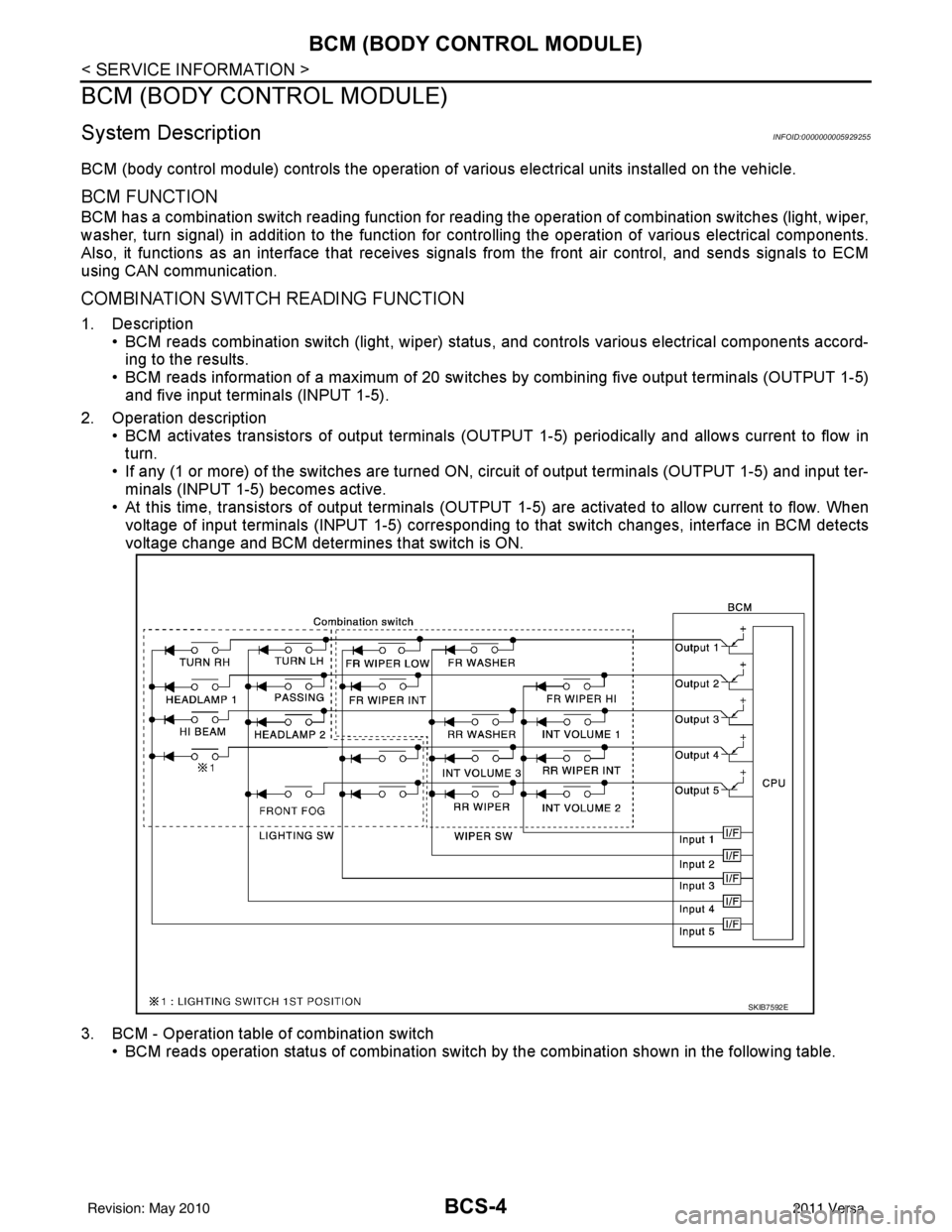
1. Description • BCM reads combination switch (light, wiper) status, and controls various electrical components accord-
ing to the results.
• BCM reads information of a maximum of 20 switches by combining five output terminals (OUTPUT 1-5)
and five input terminals (INPUT 1-5).
2. Operation description • BCM activates transistors of output terminals (OUTPU T 1-5) periodically and allows current to flow in
turn.
• If any (1 or more) of the switches are turned ON, circuit of output terminals (OUTPUT 1-5) and input ter- minals (INPUT 1-5) becomes active.
• At this time, transistors of output terminals (OUTPUT 1-5) are activated to allow current to flow. When
voltage of input terminals (INPUT 1-5) corresponding to that switch changes, interface in BCM detects
voltage change and BCM determines that switch is ON.
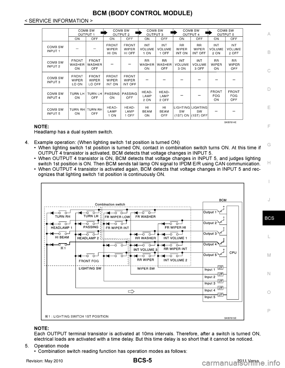
3. BCM - Operation table of combination switch • BCM reads operation status of combination switch by the combination shown in the following table.
SKIB7592E
Revision: May 2010 2011 Versa
Page 495 of 3787
BCM (BODY CONTROL MODULE)BCS-5
< SERVICE INFORMATION >
C
DE
F
G H
I
J
L
M A
B
BCS
N
O P
NOTE:
Headlamp has a dual system switch.
4. Example operation: (When lighting switch 1st position is turned ON) • When lighting switch 1st position is turned ON, contact in combination switch turns ON. At this time ifOUTPUT 4 transistor is activated, BCM detects that voltage changes in INPUT 5.
• When OUTPUT 4 transistor is ON, BCM detects that voltage changes in INPUT 5, and judges lighting
switch 1st position is ON. Then BCM sends tail lamp ON signal to IPDM E/R using CAN communication.
• When OUTPUT 4 transistor is activated again, BC M detects that voltage changes in INPUT 5 and rec-
ognizes that lighting switch 1st position is continuously ON.
NOTE:
Each OUTPUT terminal transistor is activated at 10ms intervals. Therefore, after a switch is turned ON,
electrical loads are activated with a time delay. But this time delay is so short that it cannot be noticed.
5. Operation mode • Combination switch reading functi on has operation modes as follows:
SKIB7614E
SKIB7615E
Revision: May 2010 2011 Versa
Page 497 of 3787
BCM (BODY CONTROL MODULE)BCS-7
< SERVICE INFORMATION >
C
DE
F
G H
I
J
L
M A
B
BCS
N
O P
• When CAN communication operation is detected, it switches to CAN communication status.
• When a state of the following switches changes , it switches to CAN communication state:
- Ignition switch
- Key switch (without Intelligent Key)
- Key switch and ignition knob switch (with Intelligent Key)
- Hazard switch
- Door lock/unlock switch (with power door locks)
- Front door switch (LH, RH)
- Rear door switch (LH, RH)
- Back door lock assembly (Hatchback)
- Trunk key cylinder switch (Sedan)
- Trunk lamp switch and trunk release solenoid (Sedan)
- Combination switch (passing, lighting switch 1st position, front fog lamp)
- Keyfob (lock/unlock signal) (with power door locks)
- Front door key cylinder switch LH
• When control performed only by BCM is required by switch, it shifts to CAN communication inactive mode.
• Status of combination switch reading function is changed.
SYSTEMS CONTROLLED BY BCM DIRECTLY
• Power door lock system (with power door locks). Refer to BL-23, "System Description" .
• Remote keyless entry system. Refer to BL-58, "
System Description" .
• Power window system (with power windows). Refer to GW-19, "
System Description" . NOTE
• Sunroof system (with sunroof). Refer to RF-11, "System Description". NOTE
• Room lamp timer. Refer to LT-93, "System Description" .
• Rear wiper and washer system (Hatchback). Refer to WW-27, "
System Description" .
NOTE:
Power supply only. No system control.
SYSTEMS CONTROLLED BY BCM AND IPDM E/R
• Panic system. Refer to BL-58, "System Description" .
• Vehicle security (theft warning) system. Refer to BL-218, "
System Description" .
• NVIS(NATS) system. Refer to BL-246, "
System Description" .
• Headlamp, tail lamp and battery saver control systems. Refer to LT-74, "
System Description", LT- 5 , "System
Description" or LT-27, "System Description" .
• Front fog lamp (with front fog lamps). Refer to LT-41, "
System Description" .
• Front wiper and washer system. Refer to WW-5, "
System Description" .
• Rear window defogger system. Refer to GW-51, "
System Description" .
SYSTEMS CONTROLLED BY BCM AND COMBINATION METER
• Warning chime. Refer to DI-43, "System Description" .
• Turn signal and hazard warning lamps. Refer to LT-50, "
System Description" .
SYSTEMS CONTROLLED BY BCM AND INTELLIGENT KEY UNIT (WITH INTELLIGENT KEY)
• Intelligent Key system. Refer to BL-88, "System Description" .
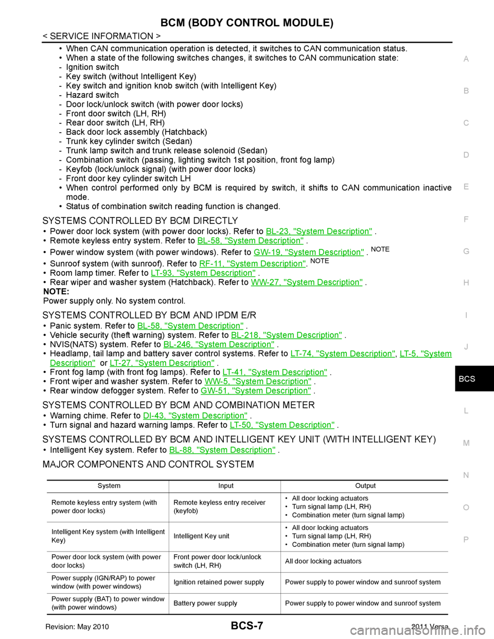
MAJOR COMPONENTS AND CONTROL SYSTEM
System Input Output
Remote keyless entry system (with
power door locks) Remote keyless entry receiver
(keyfob)• All door locking actuators
• Turn signal lamp (LH, RH)
• Combination meter (turn signal lamp)
Intelligent Key system (with Intelligent
Key) Intelligent Key unit• All door locking actuators
• Turn signal lamp (LH, RH)
• Combination meter (turn signal lamp)
Power door lock system (with power
door locks) Front power door lock/unlock
switch (LH, RH)
All door locking actuators
Power supply (IGN /RAP) to power
window (with power windows) Ignition retained power supply Power supply to power window and sunroof system
Power supply (BAT) to power window
(with power windows) Battery power supply
Power supply to power window and sunroof system
Revision: May 2010 2011 Versa
Page 520 of 3787

BL-10
< SERVICE INFORMATION >
SQUEAK AND RATTLE TROUBLE DIAGNOSES
Most of these incidents can be repaired by adjusting, securing or insulating the item(s) or component(s) caus-
ing the noise.
SUNROOF/HEADLINING
Noises in the sunroof/headlining area c an often be traced to one of the following:
1. Sunroof lid, rail, linkage or seals making a rattle or light knocking noise
2. Sun visor shaft shaking in the holder
3. Front or rear windshield touching headliner and squeaking
Again, pressing on the components to stop the noise while duplicating the conditions can isolate most of these
incidents. Repairs usually consist of insulating with felt cloth tape.
OVERHEAD CONSOLE (FRONT AND REAR)
Overhead console noises are often caused by the c onsole panel clips not being engaged correctly. Most of
these incidents are repaired by pushing up on the c onsole at the clip locations until the clips engage.
In addition look for:
1. Loose harness or harness connectors.
2. Front console map/reading lamp lense loose.
3. Loose screws at console attachment points.
SEATS
When isolating seat noise it's important to note the pos ition the seat is in and the load placed on the seat when
the noise is present. These conditions should be duplicated when verifying and isolating the cause of the
noise.
Cause of seat noise include:
1. Headrest rods and holder
2. A squeak between the seat pad cushion and frame
3. The rear seatback lock and bracket
These noises can be isolated by moving or pressing on the suspected components while duplicating the con-
ditions under which the noise occurs. Most of thes e incidents can be repaired by repositioning the component
or applying urethane tape to the contact area.
UNDERHOOD
Some interior noise may be caused by components under the hood or on the engine wall. The noise is then
transmitted into the passenger compartment.
Causes of transmitted underhood noise include:
1. Any component mounted to the engine wall
2. Components that pass through the engine wall
3. Engine wall mounts and connectors
4. Loose radiator mounting pins
5. Hood bumpers out of adjustment
6. Hood striker out of adjustment
These noises can be difficult to isolate since they cannot be reached from the interior of the vehicle. The best
method is to secure, move or insulate one component at a time and test drive the \
vehicle. Also, engine RPM
or load can be changed to isolate the noise. Repairs can usually be made by moving, adjusting, securing, or
insulating the component causing the noise.
Revision: May 2010 2011 Versa
Page 534 of 3787

BL-24
< SERVICE INFORMATION >
POWER DOOR LOCK SYSTEM
• through body grounds M57 and M61.
When the front door switch LH is ON (door is OPEN), ground is supplied
• to BCM terminal 47
• through front door switch LH terminal 2
• through front door switch LH case ground.
When the front door switch RH is ON (door is OPEN), ground is supplied
• to BCM terminal 12
• through front door switch RH terminal 2
• through front door switch RH case ground.
When the rear door switch LH is ON (door is OPEN), ground is supplied
• to BCM terminal 48
• through rear door switch LH terminal 1
• through rear door switch LH case ground.
When the rear door switch RH is ON (door is OPEN), ground is supplied
• to BCM terminal 13
• through rear door switch RH terminal 1
• through rear door switch RH case ground.
When the back door lock assembly (back door switch) ( hatchback) is ON (back door is OPEN), ground is sup-
plied
• to BCM terminal 43
• through back door lock assembly (back door switch) terminals 3 and 4
• through body grounds B117, B132 and D402.
OUTLINE
Functions available by operating the inside door lock and unlock switches
• Interlocked with the locking operation of door lock and unlock switch, door lock actuators of all doors are
locked.
• Interlocked with the unlocking operation of door lock and unlock switch, door lock actuators of all doors are
unlocked.
Functions available by operating the front door lock assembly LH (key cylinder switch)
• Interlocked with the locking operation of front door lock assembly LH (key cylinder switch), door lock actua-
tors of all doors are locked.
• When front door lock assembly LH (key cylinder switch) is unlocked, front door lock assembly LH (actuator)
is unlocked.
• When front door lock assembly LH (key cylinder swit ch) is unlocked for the second time within 5 seconds
after the first operation, front door lock assembly RH (actuator), rear door lock actuator LH and rear door
lock actuator RH are unlocked.
Key reminder door system
When door lock and unlock switch is operated to lock doors with ignition key inserted in key cylinder and any
door open, all door lock actuators are locked and then unlocked.
AUTOMATIC DOOR LOCKS (LOCK OPERATION)
The interlock door lock function is the function that locks all doors linked with the vehicle speed.
Vehicle Speed Sensing Auto Door Lock*1
All doors are locked when the vehicle speed reaches 24 km/h (15 MPH) or more.
BCM outputs the lock signal to all door lock actuators when it detects that the ignition switch is turned ON, all
doors are closed and the vehicle speed received from the combination meter via CAN communication
becomes 15 MPH (24 km/h) or more.
If a door is opened and closed at any time during one ignition cycle (OFF → ON), even after initial auto door
lock has taken place, the BCM will relock all doors when the vehicle speed reaches 15 MPH (24 km/h) or more
again.
Setting change of Automatic Door Locks (LOCK) Function
The lock operation setting of the autom atic door locks function can be changed.
With CONSULT-III
The ON/OFF switching of the automatic door locks (LOC K) function and the type selection of the automatic
door locks (LOCK) function can be performed at the WO RK SUPPORT setting of CONSULT-III. Refer to BL-
41, "CONSULT-III Function (BCM)".
Without CONSULT- III
The automatic door locks (LOCK) function can be swit ched ON/OFF by performing the following operation.
Revision: May 2010 2011 Versa
Page 579 of 3787
REMOTE KEYLESS ENTRY SYSTEMBL-69
< SERVICE INFORMATION >
C
DE
F
G H
J
K L
M A
B
BL
N
O P
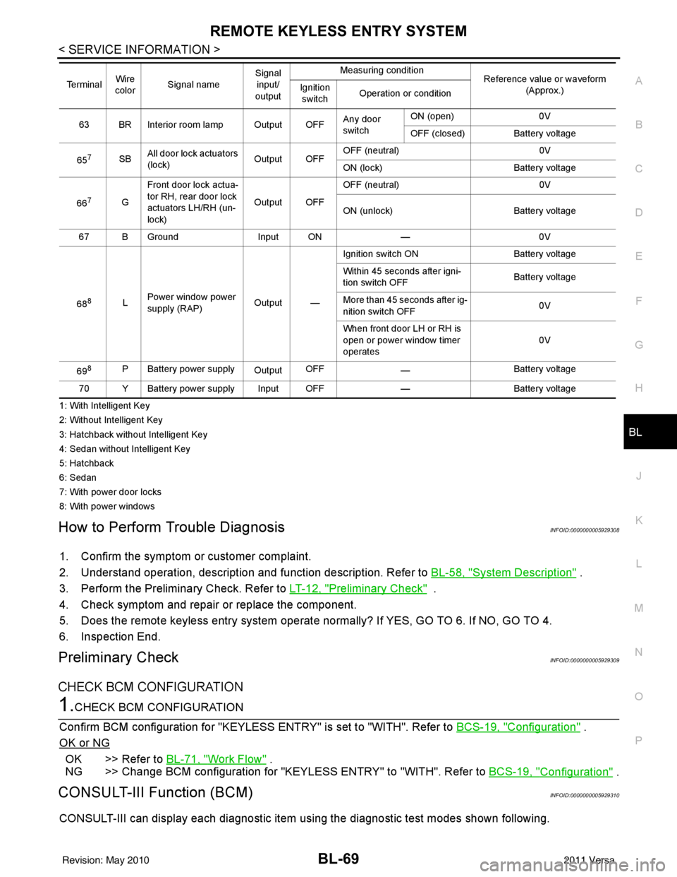
1: With Intelligent Key
2: Without Intelligent Key
3: Hatchback without Intelligent Key
4: Sedan without Intelligent Key
5: Hatchback
6: Sedan
7: With power door locks
8: With power windows
How to Perform Trouble DiagnosisINFOID:0000000005929308
1. Confirm the symptom or customer complaint.
2. Understand operation, description and function description. Refer to BL-58, "
System Description" .
3. Perform the Preliminary Check. Refer to LT-12, "
Preliminary Check" .
4. Check symptom and repair or replace the component.
5. Does the remote keyless entry system operate normally? If YES, GO TO 6. If NO, GO TO 4.
6. Inspection End.
Preliminary CheckINFOID:0000000005929309
CHECK BCM CONFIGURATION
1.CHECK BCM CONFIGURATION
Confirm BCM configuration for "KEYLESS ENTRY" is set to "WITH". Refer to BCS-19, "
Configuration" .
OK or NG
OK >> Refer to BL-71, "Work Flow" .
NG >> Change BCM configuration for "KEYLESS ENTRY" to "WITH". Refer to BCS-19, "
Configuration" .
CONSULT-III Function (BCM)INFOID:0000000005929310
CONSULT-III can display each diagnostic item using the diagnostic test modes shown following.
63 BR Interior room lamp Output OFFAny door
switchON (open)
0V
OFF (closed) Battery voltage
65
7SB All door lock actuators
(lock) Output OFFOFF (neutral)
0V
ON (lock) Battery voltage
66
7G Front door lock actua-
tor RH, rear door lock
actuators LH/RH (un-
lock) Output OFFOFF (neutral)
0V
ON (unlock) Battery voltage
67 B Ground Input ON—0V
68
8L Power window power
supply (RAP)
Output —Ignition switch ON
Battery voltage
Within 45 seconds after igni-
tion switch OFF Battery voltage
More than 45 seconds after ig-
nition switch OFF 0V
When front door LH or RH is
open or power window timer
operates 0V
69
8P Battery power supply OutputOFF
— Battery voltage
70 Y Battery power supply Input OFF —Battery voltage
Te r m i n a l
Wire
color Signal name Signal
input/
output Measuring condition
Reference value or waveform
(Approx.)
Ignition
switch Operation or condition
Revision: May 2010
2011 Versa
Page 599 of 3787

INTELLIGENT KEY SYSTEMBL-89
< SERVICE INFORMATION >
C
DE
F
G H
J
K L
M A
B
BL
N
O P
Operation Description
• When the Intelligent Key unit detects that each request sw
itch is pressed, it starts the outside key antenna
and inside key antenna corresponding to the pressed request switch and sends the request signal to the
Intelligent Key. And then, make sure that the Intelligent Key is near door.
• If the Intelligent Key is within the outside key antenna detection area, it receives the request signal and sends the key ID signal to the Intelligent Key unit.
• Intelligent Key unit receives the key ID signal and compares it with the registered key ID.
• If the key ID check result is OK, the Intelligent Ke y unit sends the door lock/unlock request signal to BCM
(Body control module) via CAN communication line.
• Intelligent Key unit sends the door lock/unlock signal and sounds Intelligent Key warning buzzer (lock: 2 times, unlock: 1 time) at the same time.
• When BCM receives the door lock/unlock signal, it oper ates door lock actuator and flashes the hazard warn-
ing lamp (lock: 2 times, unlock: 1 time) at the same time as reminder.
Operation Condition
If the following conditions are not satisfied, door lock/unlock operations are not performed even if the request
switch is operated.
*: Even with a registered Intelligent Key remaining inside the vehicle, door locks can be unlocked from outside of the vehicle with a spare
Intelligent Key as long as Key IDs are different.
Outside Key Antenna Detection Area
The outside key antenna detection area of door lock/unloc k function is in the range of approximately 80 cm
(31.50 in) surrounding the request switch (driver side, passenger side and back door or trunk area).
Hazard and Buzzer Reminder
When all doors and trunk (sedan) are locked or unlocked by each request switch, Intelligent Key\
unit sends
hazard request signal to BCM via CAN communication line.
BCM flashes hazard warning lamps as a reminder and Intelligent Key unit sounds Intelligent Key warning
buzzer(s) as a reminder.
Operating function of hazard and buzzer reminder
* : Sedan only
Auto Door Lock Function
When all doors and trunk (sedan) are locked, ignition knob sw itch is OFF (when ignition switch is not pressed)
and key switch is OFF (when mechanical key is out of ignition key cylinder), all doors are unlocked with each
request switch.
When Intelligent Key unit does not receive the following signals within 1 minute, all doors are locked.
• Door switch is ON (door is opened)
• Trunk lamp switch (sedan) is ON (trunk is opened)
• Door lock signal from Intelligent Key button
• Ignition knob switch is ON (ignition switch is pressed)
• Key switch is ON (mechanical key is inserted in ignition key cylinder)
Auto door lock mode can be changed by “AUTO RELOCK TIMER” mode in “WORK SUPPORT”. Refer to BL-
117, "CONSULT-III Application Item".
List of Operation Related Parts
Parts marked with × are the parts related to operation.
Each request switch operation Operation conditionOperation
Lock operation • All doors and trunk (sedan) are closed
• Intelligent Key is outside of the vehicle
• Intelligent Key is within outside key antenna detection area All doors lock
Unlock Operation • All doors and trunk (sedan) are closed
• Intelligent Key is outside of the vehicle
• Intelligent Key is within outside key antenna detection area*
All doors unlock
Request switch operation
Hazard warning lamp flashIntelligent Key warning buzzer (front door LH)
Intelligent Key warning buzzer (trunk)*
Unlock Once Once
Lock Twice Twice
Revision: May 2010 2011 Versa
Page 601 of 3787
INTELLIGENT KEY SYSTEMBL-91
< SERVICE INFORMATION >
C
DE
F
G H
J
K L
M A
B
BL
N
O P
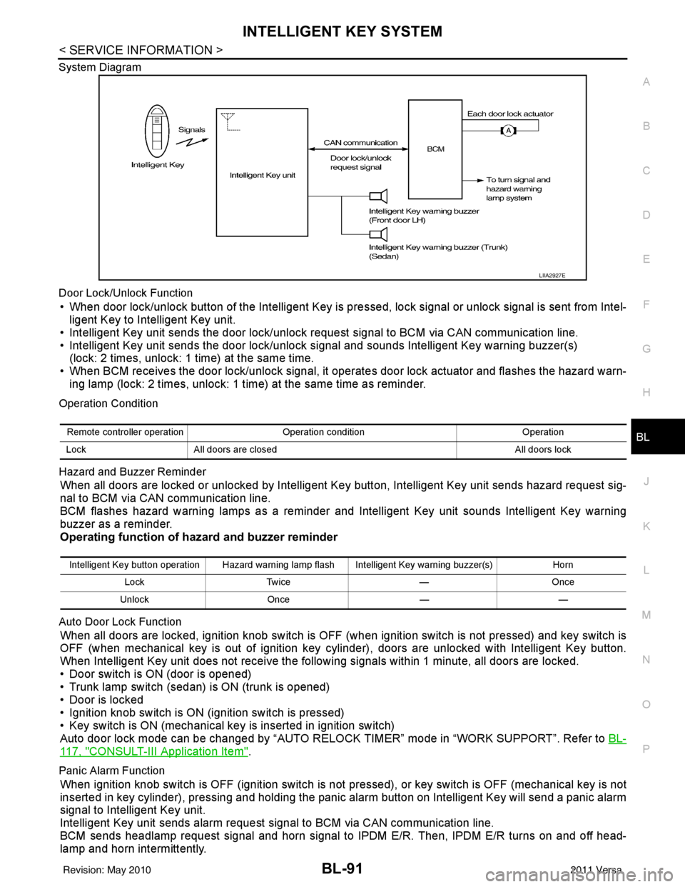
System Diagram
Door Lock/Unlock Function
• When door lock/unlock button of the Intelligent Key is pr
essed, lock signal or unlock signal is sent from Intel-
ligent Key to Intelligent Key unit.
• Intelligent Key unit sends the door lock/unlock request signal to BCM via CAN communication line.
• Intelligent Key unit sends the door lock/unlock signal and sounds Intelligent Key warning buzzer(s) (lock: 2 times, unlock: 1 time) at the same time.
• When BCM receives the door lock/unlock signal, it oper ates door lock actuator and flashes the hazard warn-
ing lamp (lock: 2 times, unlock: 1 time) at the same time as reminder.
Operation Condition
Hazard and Buzzer Reminder
When all doors are locked or unlocked by Intelligent Ke y button, Intelligent Key unit sends hazard request sig-
nal to BCM via CAN communication line.
BCM flashes hazard warning lamps as a reminder and Intelligent Key unit sounds Intelligent Key warning
buzzer as a reminder.
Operating function of hazard and buzzer reminder
Auto Door Lock Function
When all doors are locked, ignition knob switch is OFF (when ignition switch is not pressed) and key switch is
OFF (when mechanical key is out of ignition key cyli nder), doors are unlocked with Intelligent Key button.
When Intelligent Key unit does not receive the following signals within 1 minute, all doors are locked.
• Door switch is ON (door is opened)
• Trunk lamp switch (sedan) is ON (trunk is opened)
• Door is locked
• Ignition knob switch is ON (ignition switch is pressed)
• Key switch is ON (mechanical key is inserted in ignition switch)
Auto door lock mode can be changed by “AUTO RELOCK TIMER” mode in “WORK SUPPORT”. Refer to BL-
117, "CONSULT-III Application Item".
Panic Alarm Function
When ignition knob switch is OFF (ignition switch is not pressed), or key switch is OFF (mechanical key is not
inserted in key cylinder), pressing and holding the panic alarm button on Intelligent Key will send a panic alarm
signal to Intelligent Key unit.
Intelligent Key unit sends alarm request signal to BCM via CAN communication line.
BCM sends headlamp request signal and horn signal to IPDM E/R. Then, IPDM E/R turns on and off head-
lamp and horn intermittently.
LIIA2927E
Remote controller operation Operation condition Operation
Lock All doors are closed All doors lock
Intelligent Key button operation Hazard warning lamp flash Intelligent Key warning buzzer(s) Horn
Lock Twice —Once
Unlock Once ——
Revision: May 2010 2011 Versa