Page 273 of 3787
AT-256
< SERVICE INFORMATION >
OVERHAUL
MR18DE ENGINE MODELS
• Refer to AT-374, "Adjusting shims, Needle Bearings, Thrust Washers and Snap Rings".
SCIA7961E
Revision: May 2010 2011 Versa
Page 279 of 3787
AT-262
< SERVICE INFORMATION >
DISASSEMBLY
• HR16DE engine models
• MR18DE engine models
b. Remove bracket from converter housing
c. Remove converter housing by tapping it lightly.
d. Remove O-ring from differential lubricant hole.
24. Remove final drive assembly from transaxle case.
SCIA6211J
SCIA7970E
SCIA3281E
SAT228F
Revision: May 2010 2011 Versa
Page 280 of 3787
DISASSEMBLYAT-263
< SERVICE INFORMATION >
DE
F
G H
I
J
K L
M A
B
AT
N
O P
25. Remove differential side bearing outer race from transaxle case and converter housing. (MR18DE engine models)
26. Remove differential side bearing adjusting shim from transaxle case.
27. Remove RH differential side oil seal from converter housing using a suitable tool.
CAUTION:
Be careful not to scratch converter housing.
28. Remove differential lubricant tube (1) and clips (2) from con- verter housing.
: Bolt
29. Remove oil pump assembly according to the following procedures. Tool number : KV381054S0 (J-34286)
SCIA5378E
SCIA4938E
SCIA3283E
SCIA7817E
Revision: May 2010
2011 Versa
Page 287 of 3787
AT-270
< SERVICE INFORMATION >
DISASSEMBLY
41. Remove overrun clutch hub (1) from forward clutch drum.
42. Remove thrust washer (1) from overrun clutch hub (2).•Inspect thrust washer (1) and overrun clutch hub (2), and
replace if damaged or worn.
43. Remove forward clutch assembly and overrun clutch assembly (1) from transaxle case.
44. Remove needle bearing (1) and thrust washer (2) from bearing retainer.
•Inspect needle bearing (1) and thrust washer (2), and
replace damaged or worn.
45. Remove output shaft assembly according to the following procedures.
a. HR16DE engine models.
SCIA5898J
SCIA5899J
SCIA5900J
SCIA5901J
Revision: May 2010 2011 Versa
Page 288 of 3787
DISASSEMBLYAT-271
< SERVICE INFORMATION >
DE
F
G H
I
J
K L
M A
B
AT
N
O P
i. Remove side cover bolts (1), then remove side cover by lightly tapping it with a soft hammer.
CAUTION:
Be careful not to damage cover.
ii. Remove side cover gasket from side cover.
iii. Set manual shaft in "P" position to lock idler gear and output gear.
iv. Unlock both idler gear and output gear lock nuts with a suitable tool.
v. Remove idler gear and output gear lock nuts.
vi. Remove out put gear (1) and idler gear (2) using Tool (A).
vii. Removing reduction pinion gear and output shaft from transaxle case.
viii. Remove reduction pinion gear adjusting shim (1) from reduction pinion gear (2).
ix. Remove output gear adjusting spacer (3) from output shaft (4).
b. MR18DE engine models.
SCIA6039J
SAT704D
Tool number : ST27180001 (J-25726-A)
SCIA6991E
SCIA5902J
Revision: May 2010 2011 Versa
Page 323 of 3787

AT-306
< SERVICE INFORMATION >
REPAIR FOR COMPONENT PARTS
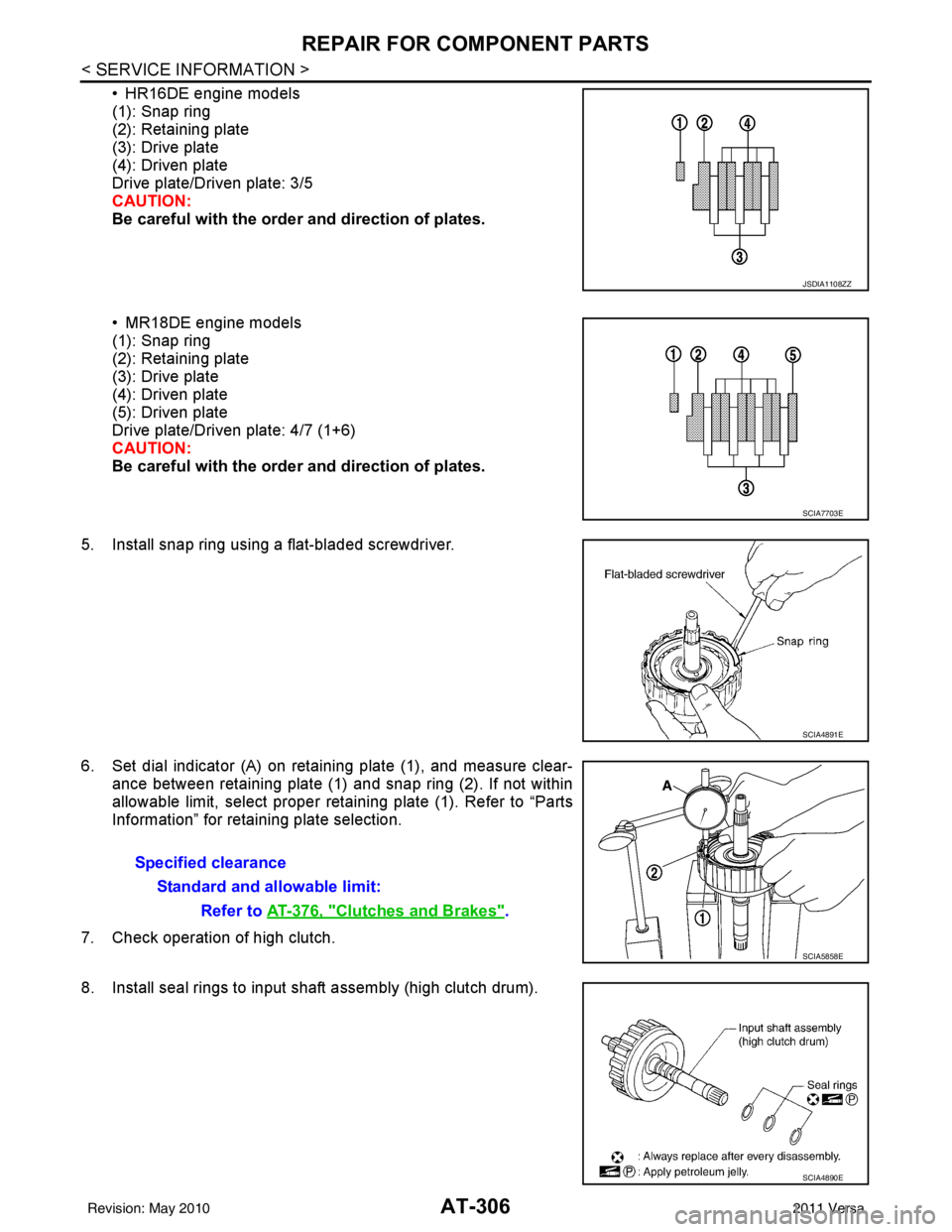
• HR16DE engine models
(1): Snap ring
(2): Retaining plate
(3): Drive plate
(4): Driven plate
Drive plate/Driven plate: 3/5
CAUTION:
Be careful with the order and direction of plates.
• MR18DE engine models
(1): Snap ring
(2): Retaining plate
(3): Drive plate
(4): Driven plate
(5): Driven plate
Drive plate/Driven plate: 4/7 (1+6)
CAUTION:
Be careful with the orde r and direction of plates.
5. Install snap ring using a flat-bladed screwdriver.
6. Set dial indicator (A) on retaining plate (1), and measure clear- ance between retaining plate (1) and snap ring (2). If not within
allowable limit, select proper retaining plate (1). Refer to “Parts
Information” for retaining plate selection.
7. Check operation of high clutch.
8. Install seal rings to input shaft assembly (high clutch drum).
JSDIA1108ZZ
SCIA7703E
SCIA4891E
Specified clearance Standard and allowable limit: Refer to AT-376, "
Clutches and Brakes".
SCIA5858E
SCIA4890E
Revision: May 2010 2011 Versa
Page 334 of 3787
REPAIR FOR COMPONENT PARTSAT-317
< SERVICE INFORMATION >
DE
F
G H
I
J
K L
M A
B
AT
N
O P
2. Install low & reverse brake piston in transaxle case while turning it.
CAUTION:
Apply ATF to inner surface of transaxle case.
3. Install spring retainer assembly (1) on low & reverse brake pis- ton (2).
4. Set Tool (A) on spring retainer assembly, and install snap ring while compressing spring retainer assembly.
CAUTION:
Set SST directly over return springs.
5. Install driven plates, dish plates, retaining plates and drive plates. • HR16DE engine models
(1): Snap ring
(2): Retaining plate
(3): Drive plate
(4): Driven plate
(5): Retaining plate
(6): Dish plate
Drive plate/Driven plate: 4/4
CAUTION:
Be careful with the order of plates
SAT239D
SCIA6020J
Tool number A: KV31103200 (J-39186)
SCIA7990E
SCIA5994E
SCIA7769E
Revision: May 2010 2011 Versa
Page 335 of 3787
AT-318
< SERVICE INFORMATION >
REPAIR FOR COMPONENT PARTS
• MR18DE engine models
(1): Snap ring
(2): Retaining plate
(3): Drive plate
(4): Driven plate
(5): Retaining plate
(6): Dish plate
Drive plate/Driven plate: 5/5
CAUTION:
Be careful with the order of plates
NOTE:
Install two dish plates fitting each installation direction with
groove displaced slightly.
6. Install snap ring (1) using a suitable tool (A).
7. Measure clearance between retaining plate and snap ring. If not within allowable limit, select proper retaining plate (front side).
Refer to “Parts Information” for retaining plate selection.
8. Check operation of low & revers e brake. Refer to "DISASSEM-
BLY".
Rear Internal Gear and Forward Clutch HubINFOID:0000000005928299
COMPONENTS
SAT254E
SCIA7039E
Specified clearance
Standard and allowable limit: Refer to AT-376, "
Clutches and Brakes".
SAT246D
Revision: May 2010 2011 Versa