2011 NISSAN LATIO engine
[x] Cancel search: enginePage 391 of 3787

AT-374
< SERVICE INFORMATION >
SERVICE DATA AND SPECIFICATIONS (SDS)
Stall Speed
INFOID:0000000005928312
Line PressureINFOID:0000000005928313
Adjusting shims, Needle Bearings , Thrust Washers and Snap RingsINFOID:0000000005928314
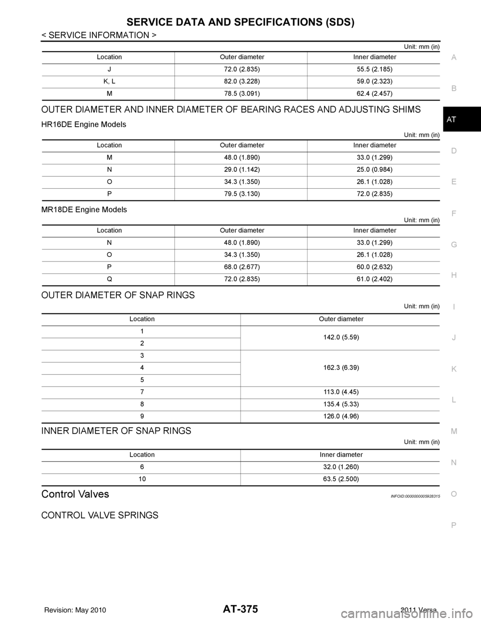
OUTER DIAMETER AND INNER DIAMETER OF NEEDLE BEARINGS
HR16DE Engine Models
Unit: mm (in)
MR18DE Engine Models
Unit: mm (in)
OUTER DIAMETER AND INNER DIAMETER OF THRUST WASHERS
HR16DE Engine Models
Unit: mm (in)
MR18DE Engine Models
Engine HR16DEMR18DE
Stall revolution (rpm) 2,250 - 2,7002,310 - 2,770
Engine speed Line pressure kPa (kg/cm2, psi)
“D”, “2” and “1” po sitions “R” position
Idle speed 500 (5.1, 73)778 (7.9, 113)
Stall speed 1,173 (12.0, 170)1,825 (18.6, 265)
LocationOuter diameter Inner diameter
A 47.0 (1.850) 32.0 (1.260)
B 35.0 (1.378) 20.1 (0.791)
C 60.0 (2.362) 42.0 (1.654)
D 60.0 (2.362) 45.0 (1.772)
E 47.0 (1.850) 30.0 (1.181)
F 42.6 (1.677) 26.1 (1.028)
G 48.0 (1.890) 33.5 (1.319)
H 59.0 (2.323) 42.1 (1.657)
LocationOuter diameter Inner diameter
A 47.0 (1.850) 32.0 (1.260)
B 35.0 (1.378) 20.1 (0.791)
C 60.0 (2.362) 42.0 (1.654)
D 60.0 (2.362) 45.0 (1.772)
E 47.0 (1.850) 30.0 (1.181)
F 42.6 (1.677) 26.1 (1.028)
G 48.0 (1.890) 33.5 (1.319)
H 55.0 (2.165) 40.5 (1.594)
I 60.0 (2.362) 40.0 (1.575)
LocationOuter diameter Inner diameter
I 72.0 (2.835) 55.5 (2.185)
J, K 82.0 (3.228) 59.0 (2.323)
L 78.5 (3.091) 62.4 (2.457)
Revision: May 2010 2011 Versa
Page 392 of 3787

SERVICE DATA AND SPECIFICATIONS (SDS)AT-375
< SERVICE INFORMATION >
DE
F
G H
I
J
K L
M A
B
AT
N
O P
Unit: mm (in)
OUTER DIAMETER AND INNER DIAMETER OF BEARING RACES AND ADJUSTING SHIMS
HR16DE Engine Models
Unit: mm (in)
MR18DE Engine Models
Unit: mm (in)
OUTER DIAMETER OF SNAP RINGS
Unit: mm (in)
INNER DIAMETER OF SNAP RINGS
Unit: mm (in)
Control ValvesINFOID:0000000005928315
CONTROL VALVE SPRINGS
Location Outer diameter Inner diameter
J 72.0 (2.835) 55.5 (2.185)
K, L 82.0 (3.228) 59.0 (2.323)
M 78.5 (3.091) 62.4 (2.457)
LocationOuter diameter Inner diameter
M 48.0 (1.890) 33.0 (1.299)
N 29.0 (1.142) 25.0 (0.984)
O 34.3 (1.350) 26.1 (1.028)
P 79.5 (3.130) 72.0 (2.835)
LocationOuter diameter Inner diameter
N 48.0 (1.890) 33.0 (1.299)
O 34.3 (1.350) 26.1 (1.028)
P 68.0 (2.677) 60.0 (2.632)
Q 72.0 (2.835) 61.0 (2.402)
Location Outer diameter
1 142.0 (5.59)
2
3
162.3 (6.39)
4
5
7 113.0 (4.45)
8 135.4 (5.33)
9 126.0 (4.96)
Location Inner diameter
6 32.0 (1.260)
10 63.5 (2.500)
Revision: May 2010 2011 Versa
Page 394 of 3787

SERVICE DATA AND SPECIFICATIONS (SDS)AT-377
< SERVICE INFORMATION >
DE
F
G H
I
J
K L
M A
B
AT
N
O P
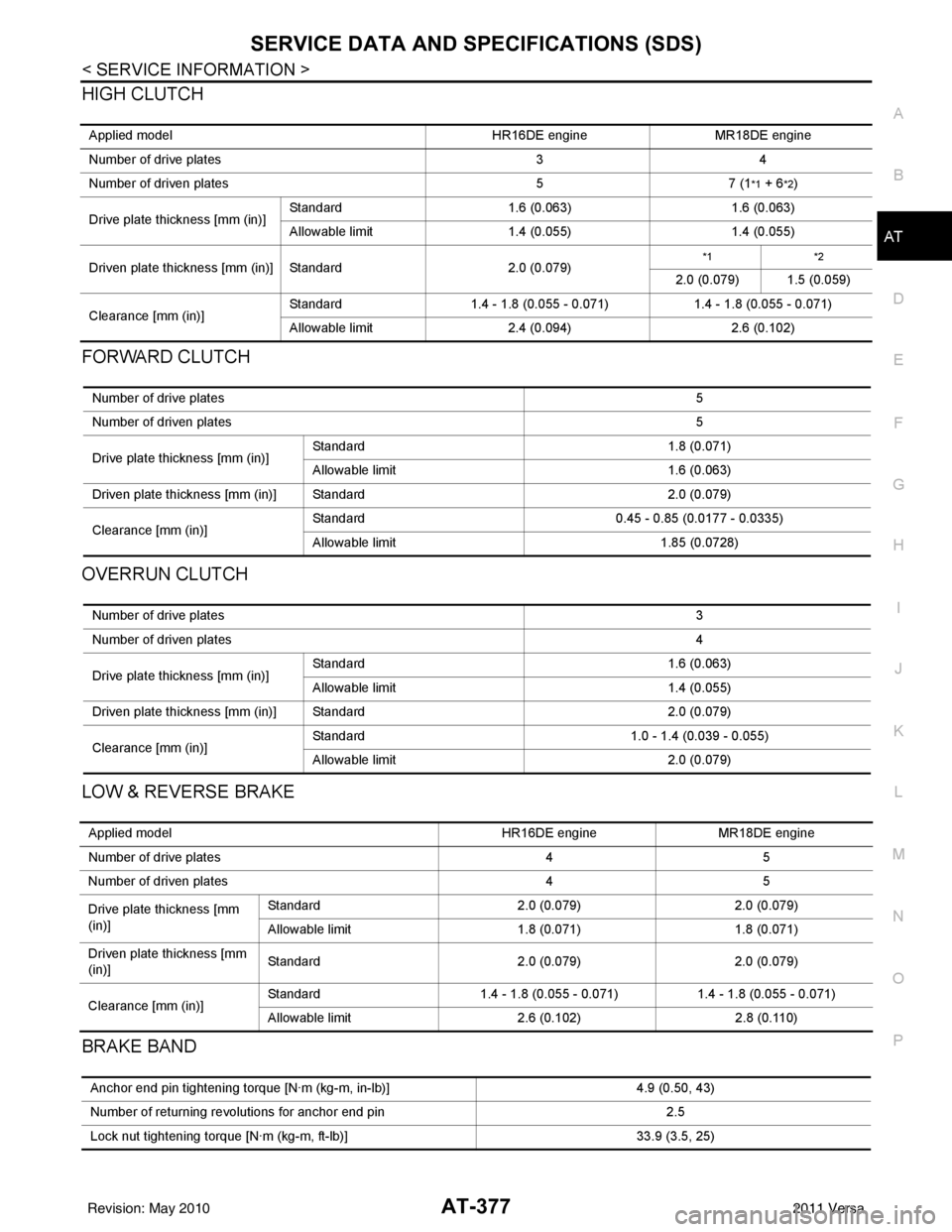
HIGH CLUTCH
FORWARD CLUTCH
OVERRUN CLUTCH
LOW & REVERSE BRAKE
BRAKE BAND
Applied model HR16DE engineMR18DE engine
Number of drive plates 34
Number of driven plates 57 (1
*1 + 6*2)
Drive plate thickness [mm (in)] Standard
1.6 (0.063) 1.6 (0.063)
Allowable limit 1.4 (0.055) 1.4 (0.055)
Driven plate thickness [mm (in)] Standard 2.0 (0.079)
*1*2
2.0 (0.079) 1.5 (0.059)
Clearance [mm (in)] Standard
1.4 - 1.8 (0.055 - 0.071) 1.4 - 1.8 (0.055 - 0.071)
Allowable limit 2.4 (0.094) 2.6 (0.102)
Number of drive plates 5
Number of driven plates 5
Drive plate thickness [mm (in)] Standard
1.8 (0.071)
Allowable limit 1.6 (0.063)
Driven plate thickness [mm (in)] Standard 2.0 (0.079)
Clearance [mm (in)] Standard
0.45 - 0.85 (0.0177 - 0.0335)
Allowable limit 1.85 (0.0728)
Number of drive plates 3
Number of driven plates 4
Drive plate thickness [mm (in)] Standard
1.6 (0.063)
Allowable limit 1.4 (0.055)
Driven plate thickness [mm (in)] Standard 2.0 (0.079)
Clearance [mm (in)] Standard
1.0 - 1.4 (0.039 - 0.055)
Allowable limit 2.0 (0.079)
Applied model HR16DE engineMR18DE engine
Number of drive plates 45
Number of driven plates 45
Drive plate thickness [mm
(in)] Standard
2.0 (0.079)2.0 (0.079)
Allowable limit 1.8 (0.071)1.8 (0.071)
Driven plate thickness [mm
(in)] Standard
2.0 (0.079)2.0 (0.079)
Clearance [mm (in)] Standard
1.4 - 1.8 (0.055 - 0.071) 1.4 - 1.8 (0.055 - 0.071)
Allowable limit 2.6 (0.102)2.8 (0.110)
Anchor end pin tightening torque [N·m (kg-m, in-lb)] 4.9 (0.50, 43)
Number of returning revolutions for anchor end pin 2.5
Lock nut tightening torque [N·m (kg-m, ft-lb)] 33.9 (3.5, 25)
Revision: May 2010 2011 Versa
Page 395 of 3787

AT-378
< SERVICE INFORMATION >
SERVICE DATA AND SPECIFICATIONS (SDS)
Final Drive
INFOID:0000000005928318
DIFFERENTIAL SIDE GEAR CLEARANCE
DIFFERENTIAL SIDE BEARING END PL AY (FOR HR16DE ENGINE MODELS)
BEARING PRELOAD (FOR MR18DE ENGINE MODELS)
TURNING TORQUE (FOR MR18DE ENGINE MODELS)
Planetary CarrierINFOID:0000000005928319
Oil PumpINFOID:0000000005928320
Input ShaftINFOID:0000000005928321
SEAL RING CLEARANCE
SEAL RING
Unit: mm (in)
Reduction Pinion GearINFOID:0000000005928322
TURNING TORQUE
Band ServoINFOID:0000000005928323
RETURN SPRINGS
Clearance between side gear and differential case with washer [mm (in)] 0.1 - 0.2 (0.004 - 0.008)
Differential side bearing end play mm (in)0 - 0.15 (0 - 0.0059)
Differential side bearing preload mm (in)0.05 - 0.09 (0.0020 - 0.0035)
Turning torque of final drive assembly N-m (kg-cm, in-lb)0.68 - 1.26 (7.0 - 13.0, 6.0 - 11.0)
Clearance between planetary carrier and pinion washer [mm (in)]Standard 0.15 - 0.70 (0.0059 - 0.0276)
Allowable limit
0.80 (0.0315)
Oil pump side clearance 0.02 - 0.04 (0.0008 - 0.0016)
Clearance between oil pump housing and outer gear [mm (in)] Standard
0.08 - 0.15 (0.0031 - 0.0059)
Allowable limit 0.15 (0.0059)
Oil pump cover seal ring clearance [mm (in)] Standard
0.10 - 0.25 (0.0039 - 0.0098)
Allowable limit 0.25 (0.0098)
Input shaft seal ring clearance [mm (in)] Standard 0.08 - 0.23 (0.0031 - 0.0091)
Allowable limit
0.23 (0.091)
Outer diameter Inner diameter Width
24 (0.94) 20.4 (0.803) 1.97 (0.0776)
Turning torque of reduction pinion gear [N·m (kg-m, in-lb)] 0.11 - 0.69 (0.01 - 0.07, 1 - 6)
Revision: May 2010 2011 Versa
Page 396 of 3787

SERVICE DATA AND SPECIFICATIONS (SDS)AT-379
< SERVICE INFORMATION >
DE
F
G H
I
J
K L
M A
B
AT
N
O P
Unit: mm (in)
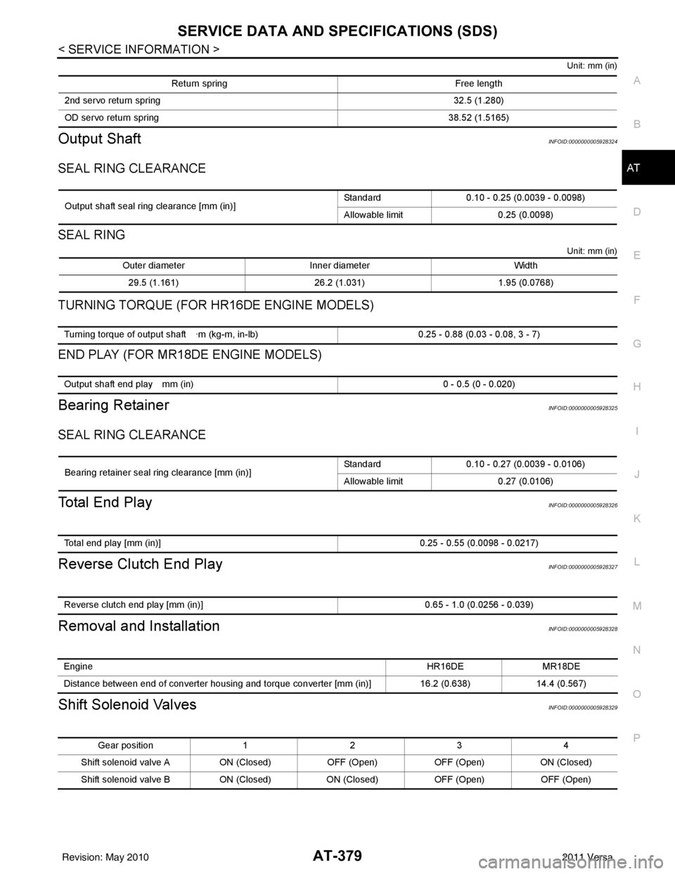
Output ShaftINFOID:0000000005928324
SEAL RING CLEARANCE
SEAL RING
Unit: mm (in)
TURNING TORQUE (FOR HR16DE ENGINE MODELS)
END PLAY (FOR MR18DE ENGINE MODELS)
Bearing RetainerINFOID:0000000005928325
SEAL RING CLEARANCE
Total End PlayINFOID:0000000005928326
Reverse Clutch End PlayINFOID:0000000005928327
Removal and InstallationINFOID:0000000005928328
Shift Solenoid ValvesINFOID:0000000005928329
Return spring Free length
2nd servo return sp ring 32.5 (1.280)
OD servo return sp ring 38.52 (1.5165)
Output shaft seal ring clearance [mm (in)]Standard 0.10 - 0.25 (0.0039 - 0.0098)
Allowable limit
0.25 (0.0098)
Outer diameter Inner diameter Width
29.5 (1.161) 26.2 (1.031)1.95 (0.0768)
Turning torque of output shaft ·m (kg-m, in-lb) 0.25 - 0.88 (0.03 - 0.08, 3 - 7)
Output shaft end play mm (in) 0 - 0.5 (0 - 0.020)
Bearing retainer seal ring clearance [mm (in)]Standard 0.10 - 0.27 (0.0039 - 0.0106)
Allowable limit
0.27 (0.0106)
Total end play [mm (in)] 0.25 - 0.55 (0.0098 - 0.0217)
Reverse clutch end play [mm (in)] 0.65 - 1.0 (0.0256 - 0.039)
Engine HR16DE MR18DE
Distance between end of converter housing and torque converter [mm (in)] 16.2 (0.638)14.4 (0.567)
Gear position 1234
Shift solenoid valve A ON (Closed)OFF (Open)OFF (Open)ON (Closed)
Shift solenoid valve B ON (Closed)ON (Closed) OFF (Open)OFF (Open)
Revision: May 2010 2011 Versa
Page 400 of 3787
![NISSAN LATIO 2011 Service Repair Manual PRECAUTIONSAV-3
< SERVICE INFORMATION > [AUDIO WITHOUT NAVIGATION]
C
D
E
F
G H
I
J
L
M A
B
AV
N
O P
SERVICE INFORMATION
PRECAUTIONS
Precaution for Supplemental Restraint System (SRS) "AIR BAG" and "S NISSAN LATIO 2011 Service Repair Manual PRECAUTIONSAV-3
< SERVICE INFORMATION > [AUDIO WITHOUT NAVIGATION]
C
D
E
F
G H
I
J
L
M A
B
AV
N
O P
SERVICE INFORMATION
PRECAUTIONS
Precaution for Supplemental Restraint System (SRS) "AIR BAG" and "S](/manual-img/5/57357/w960_57357-399.png)
PRECAUTIONSAV-3
< SERVICE INFORMATION > [AUDIO WITHOUT NAVIGATION]
C
D
E
F
G H
I
J
L
M A
B
AV
N
O P
SERVICE INFORMATION
PRECAUTIONS
Precaution for Supplemental Restraint System (SRS) "AIR BAG" and "SEAT BELT
PRE-TENSIONER"
INFOID:0000000006412032
The Supplemental Restraint System such as “AIR BAG” and “SEAT BELT PRE-TENSIONER”, used along
with a front seat belt, helps to reduce the risk or severi ty of injury to the driver and front passenger for certain
types of collision. This system includes seat belt switch inputs and dual stage front air bag modules. The SRS
system uses the seat belt switches to determine the front air bag deployment, and may only deploy one front
air bag, depending on the severity of a collision and w hether the front occupants are belted or unbelted.
Information necessary to service the system safely is included in the SRS and SB section of this Service Man-
ual.
WARNING:
• To avoid rendering the SRS inoper ative, which could increase the risk of personal injury or death in
the event of a collision which would result in air bag inflation, all maintenance must be performed by
an authorized NISSAN/INFINITI dealer.
• Improper maintenance, including in correct removal and installation of the SRS can lead to personal
injury caused by unintentional act ivation of the system. For removal of Spiral Cable and Air Bag
Module, see the SRS section.
• Do not use electrical test equipm ent on any circuit related to the SRS unless instructed to in this
Service Manual. SRS wiring harnesses can be identi fied by yellow and/or orange harnesses or har-
ness connectors.
PRECAUTIONS WHEN USING POWER TOOLS (AIR OR ELECTRIC) AND HAMMERS
WARNING:
• When working near the Airbag Diagnosis Sensor Un it or other Airbag System sensors with the Igni-
tion ON or engine running, DO NOT use air or el ectric power tools or strike near the sensor(s) with a
hammer. Heavy vibration could activate the sensor( s) and deploy the air bag(s), possibly causing
serious injury.
• When using air or electric power tools or hammers, always switch the Ignition OFF, disconnect the battery, and wait at least 3 minutes before performing any service.
Precaution Necessary for Steering Wheel Rotation After Battery Disconnect
INFOID:0000000006412033
NOTE:
• This Procedure is applied only to models with Intelligent Key system and NATS (NISSAN ANTI-THEFT SYS-
TEM).
• Remove and install all control units after disconnecti ng both battery cables with the ignition knob in the
″ LOCK ″ position.
• Always use CONSULT-III to perform self-diagnosis as a part of each function inspection after finishing work.
If DTC is detected, perform trouble diagnosis according to self-diagnostic results.
For models equipped with the Intelligent Key system and NATS , an electrically controlled steering lock mech-
anism is adopted on the key cylinder.
For this reason, if the battery is disconnected or if the battery is discharged, the steering wheel will lock and
steering wheel rotation will become impossible.
If steering wheel rotation is required when battery power is interrupted, follow the procedure below before
starting the repair operation.
OPERATION PROCEDURE
1. Connect both battery cables. NOTE:
Supply power using jumper cables if battery is discharged.
2. Use the Intelligent Key or mechanical key to turn the ignition switch to the ″ACC ″ position. At this time, the
steering lock will be released.
3. Disconnect both battery cables. The steering lock will remain released and the steering wheel can be
rotated.
4. Perform the necessary repair operation.
Revision: May 2010 2011 Versa
Page 417 of 3787
![NISSAN LATIO 2011 Service Repair Manual AV-20
< SERVICE INFORMATION >[AUDIO WITHOUT NAVIGATION]
AUDIO
Trouble Diagnosis
INFOID:0000000006217253
The vehicle itself can be a source of noise if noise prevention parts or electrical equipment i NISSAN LATIO 2011 Service Repair Manual AV-20
< SERVICE INFORMATION >[AUDIO WITHOUT NAVIGATION]
AUDIO
Trouble Diagnosis
INFOID:0000000006217253
The vehicle itself can be a source of noise if noise prevention parts or electrical equipment i](/manual-img/5/57357/w960_57357-416.png)
AV-20
< SERVICE INFORMATION >[AUDIO WITHOUT NAVIGATION]
AUDIO
Trouble Diagnosis
INFOID:0000000006217253
The vehicle itself can be a source of noise if noise prevention parts or electrical equipment is malfunctioning.
Check if noise is caused and/or changed by engine speed, ignition switch turned to each position, and opera-
tion of each piece of electrical equipment, and then determine the cause.
NOTE:
The majority of the audio malfunctions are the result of outside causes (damaged CD, electromagnetic inter-
ference, etc.). Check the sympto ms below to diagnose the malfunction.
12
(BR) Ground
iPod® sound signal RH Input Ignition
switch ON When iPod® mode is se-
lected.
15 — Shield — —— —
16
(L) —AV communication signal
(H) Input/
Output ——
—
17
(P) Ground Ground
—Ignition
switch ON — 0
V
18 — Shield — —— —
19 — Shield — —— —
20
(R) Ground iPod® battery charge Output Ignition
switch ON Connected to iPod®.
5.0V
21
(L) Ground
iPod® connection recogni-
tion signal InputIgnition
switch
ON Not connected to iPod®.
4.0V
Connected to iPod®. 0V
22
(O) Ground ACCESSORY-DETECT — Ignition
switch ON Connected to iPod®.
0V
23 — Shield — —— —
24
(Y) Ground iPod® sound signal LH Input Ignition
switch ON When iPod® mode is se-
lected.
Terminal
(Wire color) Description
ConditionReference value
(Approx.)
+ – Signal nameInput/
Output
SKIB3609E
SKIB3609E
Symptom Check item
Audio system does not work properly. • Audio unit power supply circuit. Refer to
AV- 2 2 , "
Power Supply
Circuit Inspection" .
• Audio unit. Refer to AV- 2 9 , "
Removal and Installation" .
No sound can be heard from all speakers. • Speaker circuit shorted to ground. Refer to
AV- 9 , "
Wiring Dia-
gram - AUDIO -" .
• Audio unit. Refer to AV- 2 9 , "
Removal and Installation" .
Revision: May 2010 2011 Versa
Page 418 of 3787
![NISSAN LATIO 2011 Service Repair Manual AUDIOAV-21
< SERVICE INFORMATION > [AUDIO WITHOUT NAVIGATION]
C
D
E
F
G H
I
J
L
M A
B
AV
N
O P
NOTE:
Noise resulting from variations in field strength, such as fading noise and multi-path noise, or e NISSAN LATIO 2011 Service Repair Manual AUDIOAV-21
< SERVICE INFORMATION > [AUDIO WITHOUT NAVIGATION]
C
D
E
F
G H
I
J
L
M A
B
AV
N
O P
NOTE:
Noise resulting from variations in field strength, such as fading noise and multi-path noise, or e](/manual-img/5/57357/w960_57357-417.png)
AUDIOAV-21
< SERVICE INFORMATION > [AUDIO WITHOUT NAVIGATION]
C
D
E
F
G H
I
J
L
M A
B
AV
N
O P
NOTE:
Noise resulting from variations in field strength, such as fading noise and multi-path noise, or external noise
from trains and other sources. It is not a malfunction.
• Fading noise: This noise occurs because of variations in the field strength in a narrow range due to moun-
tains or buildings blocking the signal.
• Multi-path noise: This noise results from the waves sent directly from the broadcast station arriving at the antenna at a different time from the waves t hat reflect off of mountains or buildings.
Noise InspectionINFOID:0000000005931285
The vehicle itself can be a source of noise if noise prevention parts or electrical equipment is malfunctioning.
Check if noise is caused and/or changed by engine speed, ignition switch turned to each position, and opera-
tion of each piece of electrical equipment, and determine the cause.
NOTE:
The source of the noise can be found easily by listening to the noise while removing the fuses of electrical
components, one by one.
TYPE OF NOISE AND POSSIBLE CAUSE
No sound can be heard from one or several speakers. • Open or short in audio signal circuit between audio unit and front
speaker. Refer to AV- 2 4 , "
Sound Is Not Heard from Front Door
Speaker (Base System)" or AV- 2 6 , "Sound Is Not Heard from
Front Door Speaker or Tweeter (Premium System)" .
• Front speaker. Refer to AV- 2 4 , "
Sound Is Not Heard from Front
Door Speaker (Base System)" or AV- 2 6 , "Sound Is Not Heard
from Front Door Speaker or Tweeter (Premium System)" .
• Open or short in audio signal circuit between audio unit and rear
speaker. Refer to AV- 2 5 , "
Sound Is Not Heard from Rear Door
Speaker (Base System)" or AV- 2 7 , "Sound Is Not Heard from
Rear Door Speaker (Premium System)" .
• Rear speaker. Refer to AV- 2 5 , "
Sound Is Not Heard from Rear
Door Speaker (Base System)" or AV- 2 7 , "Sound Is Not Heard
from Rear Door Speaker (Premium System)" .
• Tweeter (mid level and premium system) AV- 2 6 , "
Sound Is Not
Heard from Front Door Speaker or Tweeter (Premium System)"
or AV- 2 7 , "
Sound Is Not Heard from Rear Door Speaker (Premi-
um System)" .
• Audio unit. Refer to AV- 2 9 , "
Removal and Installation" .
No sound can be heard from radio or noise is heard. • Antenna feeder. Refer to
AV- 3 3 , "
Location of Antenna" .
• Antenna. Refer to AV- 3 3 , "
Location of Antenna" .
• Audio unit. Refer to AV- 2 9 , "
Removal and Installation" .
Symptom
Check item
Occurrence condition Possible cause
Occurs only when engine is ON. A continuous growling noise occurs. The speed of
the noise varies with changes in the engine speed.
Ignition components
A whistling noise occurs while the engine speed is
high. A booming noise occurs while the engine is
running and the lighting switch is ON. Generator
Noise only occurs when various
electrical components are oper-
ating. A cracking or snapping sound occurs with the op-
eration of various switches.
Relay malfunction, radio malfunction
The noise occurs when various motors are operat-
ing. • Motor case ground
•Motor
The noise occurs constantly, not just under certain conditions. • Rear defogger coil malfunction
• Open circuit in printed heater
A cracking or snapping sound occurs while the vehicle is being driven, especially when
it is vibrating excessively. • Ground wire of body parts.
• Ground due to improper part installation
• Wiring connections or a short circuit
Revision: May 2010
2011 Versa