2011 NISSAN LATIO lock
[x] Cancel search: lockPage 370 of 3787
ASSEMBLYAT-353
< SERVICE INFORMATION >
DE
F
G H
I
J
K L
M A
B
AT
N
O P
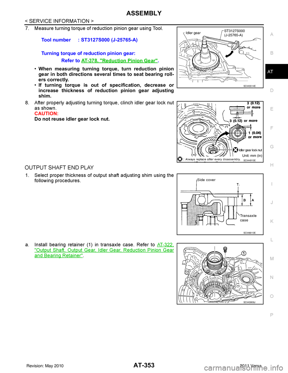
7. Measure turning torque of reduction pinion gear using Tool.
•When measuring turning torq ue, turn reduction pinion
gear in both directions several times to seat bearing roll-
ers correctly.
• If turning torque is out of specification, decrease or
increase thickness of reductio n pinion gear adjusting
shim.
8. After properly adjusting turning torque, clinch idler gear lock nut as shown.
CAUTION:
Do not reuse idler gear lock nut.
OUTPUT SHAFT END PLAY
1. Select proper thickness of output shaft adjusting shim using the
following procedures.
a. Install bearing retainer (1) in transaxle case. Refer to AT-322,
"Output Shaft, Output Gear, Idler Gear, Reduction Pinion Gear
and Bearing Retainer".
Tool number : ST3127S000 (J-25765-A)
Turning torque of reduction pinion gear:
Refer to AT-378, "
Reduction Pinion Gear".
SCIA5514E
SCIA4915E
SCIA8013E
SCIA5909J
Revision: May 2010 2011 Versa
Page 373 of 3787
AT-356
< SERVICE INFORMATION >
ASSEMBLY
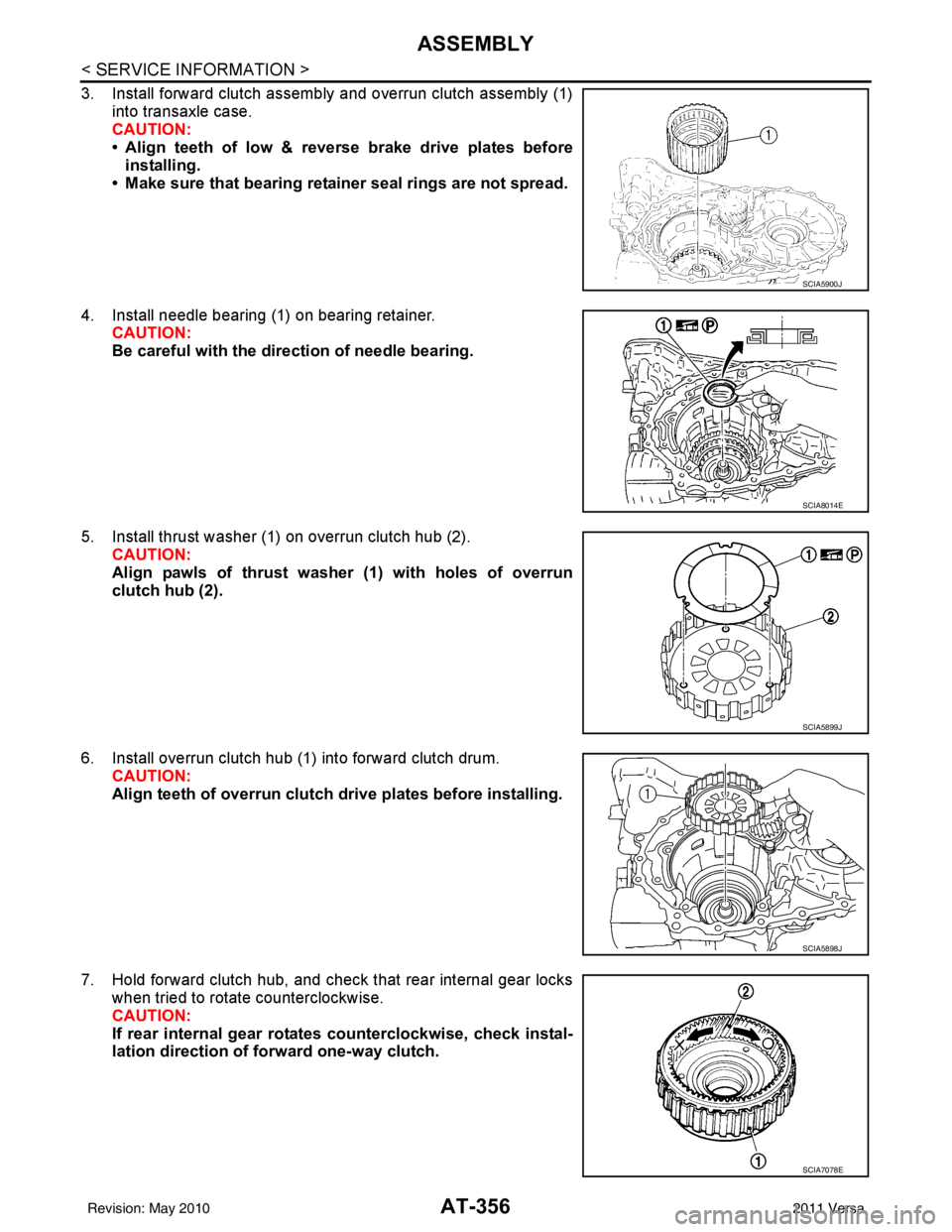
3. Install forward clutch assembly and overrun clutch assembly (1)into transaxle case.
CAUTION:
• Align teeth of low & reverse brake drive plates beforeinstalling.
• Make sure that bearing retainer seal rings are not spread.
4. Install needle bearing (1) on bearing retainer. CAUTION:
Be careful with the dir ection of needle bearing.
5. Install thrust washer (1) on overrun clutch hub (2). CAUTION:
Align pawls of thrust washer (1) with holes of overrun
clutch hub (2).
6. Install overrun clutch hub (1) into forward clutch drum. CAUTION:
Align teeth of overrun clutch drive plates before installing.
7. Hold forward clutch hub, and check that rear internal gear locks when tried to rotate counterclockwise.
CAUTION:
If rear internal gear rotat es counterclockwise, check instal-
lation direction of forward one-way clutch.
SCIA5900J
SCIA8014E
SCIA5899J
SCIA5898J
SCIA7078E
Revision: May 2010 2011 Versa
Page 375 of 3787
AT-358
< SERVICE INFORMATION >
ASSEMBLY
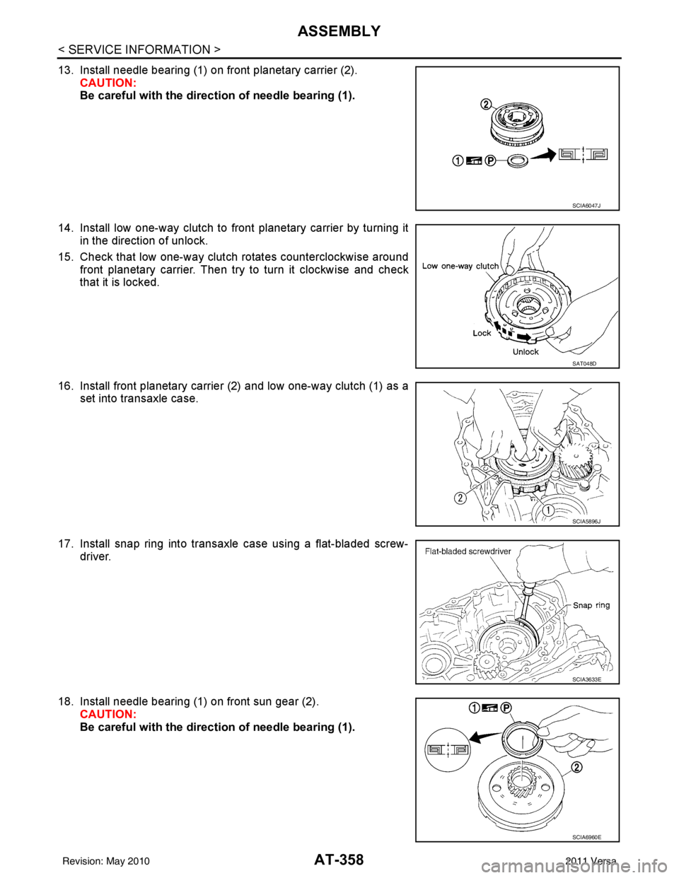
13. Install needle bearing (1) on front planetary carrier (2).CAUTION:
Be careful with the direct ion of needle bearing (1).
14. Install low one-way clutch to front planetary carrier by turning it in the direction of unlock.
15. Check that low one-way clutch rotates counterclockwise around front planetary carrier. Then try to turn it clockwise and check
that it is locked.
16. Install front planetary carrier (2) and low one-way clutch (1) as a set into transaxle case.
17. Install snap ring into transaxle case using a flat-bladed screw- driver.
18. Install needle bearing (1) on front sun gear (2). CAUTION:
Be careful with the direct ion of needle bearing (1).
SCIA6047J
SAT048D
SCIA5896J
SCIA3633E
SCIA6960E
Revision: May 2010 2011 Versa
Page 381 of 3787
AT-364
< SERVICE INFORMATION >
ASSEMBLY
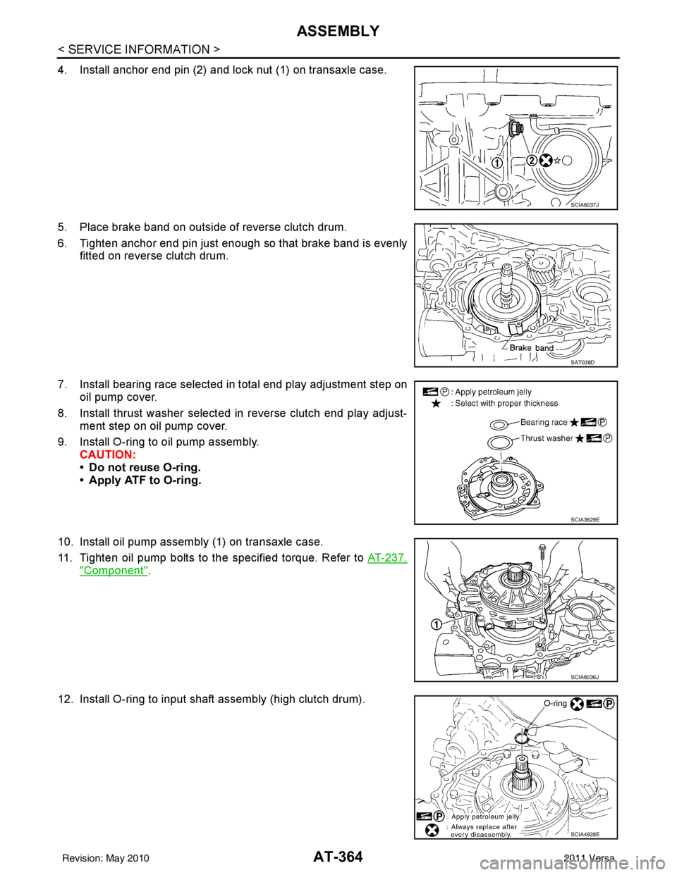
4. Install anchor end pin (2) and lock nut (1) on transaxle case.
5. Place brake band on outside of reverse clutch drum.
6. Tighten anchor end pin just enough so that brake band is evenlyfitted on reverse clutch drum.
7. Install bearing race selected in total end play adjustment step on oil pump cover.
8. Install thrust washer selected in reverse clutch end play adjust- ment step on oil pump cover.
9. Install O-ring to oil pump assembly. CAUTION:
• Do not reuse O-ring.
• Apply ATF to O-ring.
10. Install oil pump assembly (1) on transaxle case.
11. Tighten oil pump bolts to the specified torque. Refer to AT-237,
"Component".
12. Install O-ring to input shaft assembly (high clutch drum).
SCIA6037J
SAT038D
SCIA3629E
SCIA6036J
SCIA4928E
Revision: May 2010 2011 Versa
Page 382 of 3787
ASSEMBLYAT-365
< SERVICE INFORMATION >
DE
F
G H
I
J
K L
M A
B
AT
N
O P
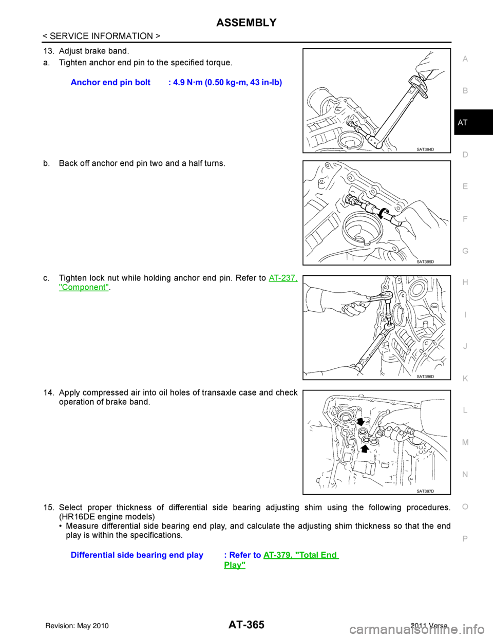
13. Adjust brake band.
a. Tighten anchor end pin to the specified torque.
b. Back off anchor end pin two and a half turns.
c. Tighten lock nut while holding anchor end pin. Refer to AT-237,
"Component".
14. Apply compressed air into oil holes of transaxle case and check operation of brake band.
15. Select proper thickness of differential side bear ing adjusting shim using the following procedures.
(HR16DE engine models)
• Measure differential side bearing end play, and calculat e the adjusting shim thickness so that the end
play is within the specifications. Anchor end pin bolt : 4.9 N·m (0.50 kg-m, 43 in-lb)
SAT394D
SAT395D
SAT396D
SAT397D
Differential side bearin
g end play : Refer to AT-379, "Total End
Play"
Revision: May 2010 2011 Versa
Page 390 of 3787
SERVICE DATA AND SPECIFICATIONS (SDS)AT-373
< SERVICE INFORMATION >
DE
F
G H
I
J
K L
M A
B
AT
N
O P
SERVICE DATA AND SPECIFICATIONS (SDS)
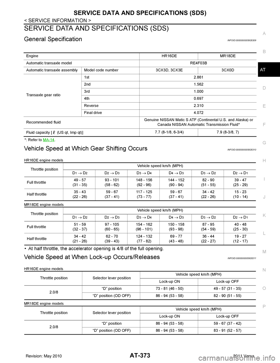
General SpecificationINFOID:0000000005928309
*: Refer to MA-14.
Vehicle Speed at Which Gear Shifting OccursINFOID:0000000005928310
HR16DE engine models
MR18DE engine models
• At half throttle, the accelerator opening is 4/8 of the full opening.
Vehicle Speed at When Lock-up Occurs/ReleasesINFOID:0000000005928311
HR16DE engine models
MR18DE engine models
Engine HR16DEMR18DE
Automatic transaxle model RE4F03B
Automatic transaxle assembly Model code number 3CX3D, 3CX3E3CX0D
Transaxle gear ratio 1st
2.861
2nd 1.562
3rd 1.000
4th 0.697
Reverse 2.310
Final drive 4.072
Recommended fluid Genuine NISSAN Matic S ATF (Continental U.S. and Alaska) or
Canada NISSAN Automatic Transmission Fluid*
Fluid capacity [ (US qt, Imp qt)] 7.7 (8-1/8, 6-3/4)
7.9 (8-3/8, 7)
Throttle position Vehicle speed km/h (MPH)
D1 → D2D2 → D3D3 → D4D4 → D3D3 → D2D2 → D1
Full throttle 49 - 57
(31 - 35) 93 - 101
(58 - 62) 148 - 156
(92 - 96) 144 - 152
(90 - 94) 82 - 90
(51 - 55) 39 - 47
(25 - 29)
Half throttle 35 - 43
(22 - 26) 59 - 67
(37 - 41) 117 - 125
(73 - 77) 59 - 67
(37 - 41) 34 - 42
(22 - 26) 15 - 23
(10 - 14)
Throttle position Vehicle speed km/h (MPH)
D
1 → D2D2 → D3D3 → D4D4 → D3D3 → D2D2 → D1
Full throttle 51 - 59
(32 - 37) 97 - 105
(60 - 65) 154 - 162
(96 - 101) 150 - 158
(93 - 98) 87 - 95
(54 - 59) 40 - 48
(25 - 30)
Half throttle 34 - 42
(21 - 26) 62 - 70
(39 - 43) 124 - 132
(77 - 82) 69 - 77
(43 - 48) 36 - 44
(22 - 27) 19 - 27
(12 - 17)
Throttle position Selector lever position Vehicle speed km/h (MPH)
Lock-up ON Lock-up OFF
2.0/8 “D” position
73 - 81 (46 - 50) 49 - 57 (31 - 35)
“D” position (OD OFF) 86 - 94 (53 - 58) 82 - 90 (51 - 55)
Throttle position Selector lever position Vehicle speed km/h (MPH)
Lock-up ON Lock-up OFF
2.0/8 “D” position
86 - 94 (53 - 58) 59 - 67 (37 - 42)
“D” position (OD OFF) 86 - 94 (53 - 58) 83 - 91 (52 - 57)
Revision: May 2010 2011 Versa
Page 394 of 3787

SERVICE DATA AND SPECIFICATIONS (SDS)AT-377
< SERVICE INFORMATION >
DE
F
G H
I
J
K L
M A
B
AT
N
O P
HIGH CLUTCH
FORWARD CLUTCH
OVERRUN CLUTCH
LOW & REVERSE BRAKE
BRAKE BAND
Applied model HR16DE engineMR18DE engine
Number of drive plates 34
Number of driven plates 57 (1
*1 + 6*2)
Drive plate thickness [mm (in)] Standard
1.6 (0.063) 1.6 (0.063)
Allowable limit 1.4 (0.055) 1.4 (0.055)
Driven plate thickness [mm (in)] Standard 2.0 (0.079)
*1*2
2.0 (0.079) 1.5 (0.059)
Clearance [mm (in)] Standard
1.4 - 1.8 (0.055 - 0.071) 1.4 - 1.8 (0.055 - 0.071)
Allowable limit 2.4 (0.094) 2.6 (0.102)
Number of drive plates 5
Number of driven plates 5
Drive plate thickness [mm (in)] Standard
1.8 (0.071)
Allowable limit 1.6 (0.063)
Driven plate thickness [mm (in)] Standard 2.0 (0.079)
Clearance [mm (in)] Standard
0.45 - 0.85 (0.0177 - 0.0335)
Allowable limit 1.85 (0.0728)
Number of drive plates 3
Number of driven plates 4
Drive plate thickness [mm (in)] Standard
1.6 (0.063)
Allowable limit 1.4 (0.055)
Driven plate thickness [mm (in)] Standard 2.0 (0.079)
Clearance [mm (in)] Standard
1.0 - 1.4 (0.039 - 0.055)
Allowable limit 2.0 (0.079)
Applied model HR16DE engineMR18DE engine
Number of drive plates 45
Number of driven plates 45
Drive plate thickness [mm
(in)] Standard
2.0 (0.079)2.0 (0.079)
Allowable limit 1.8 (0.071)1.8 (0.071)
Driven plate thickness [mm
(in)] Standard
2.0 (0.079)2.0 (0.079)
Clearance [mm (in)] Standard
1.4 - 1.8 (0.055 - 0.071) 1.4 - 1.8 (0.055 - 0.071)
Allowable limit 2.6 (0.102)2.8 (0.110)
Anchor end pin tightening torque [N·m (kg-m, in-lb)] 4.9 (0.50, 43)
Number of returning revolutions for anchor end pin 2.5
Lock nut tightening torque [N·m (kg-m, ft-lb)] 33.9 (3.5, 25)
Revision: May 2010 2011 Versa
Page 400 of 3787
![NISSAN LATIO 2011 Service Repair Manual PRECAUTIONSAV-3
< SERVICE INFORMATION > [AUDIO WITHOUT NAVIGATION]
C
D
E
F
G H
I
J
L
M A
B
AV
N
O P
SERVICE INFORMATION
PRECAUTIONS
Precaution for Supplemental Restraint System (SRS) "AIR BAG" and "S NISSAN LATIO 2011 Service Repair Manual PRECAUTIONSAV-3
< SERVICE INFORMATION > [AUDIO WITHOUT NAVIGATION]
C
D
E
F
G H
I
J
L
M A
B
AV
N
O P
SERVICE INFORMATION
PRECAUTIONS
Precaution for Supplemental Restraint System (SRS) "AIR BAG" and "S](/manual-img/5/57357/w960_57357-399.png)
PRECAUTIONSAV-3
< SERVICE INFORMATION > [AUDIO WITHOUT NAVIGATION]
C
D
E
F
G H
I
J
L
M A
B
AV
N
O P
SERVICE INFORMATION
PRECAUTIONS
Precaution for Supplemental Restraint System (SRS) "AIR BAG" and "SEAT BELT
PRE-TENSIONER"
INFOID:0000000006412032
The Supplemental Restraint System such as “AIR BAG” and “SEAT BELT PRE-TENSIONER”, used along
with a front seat belt, helps to reduce the risk or severi ty of injury to the driver and front passenger for certain
types of collision. This system includes seat belt switch inputs and dual stage front air bag modules. The SRS
system uses the seat belt switches to determine the front air bag deployment, and may only deploy one front
air bag, depending on the severity of a collision and w hether the front occupants are belted or unbelted.
Information necessary to service the system safely is included in the SRS and SB section of this Service Man-
ual.
WARNING:
• To avoid rendering the SRS inoper ative, which could increase the risk of personal injury or death in
the event of a collision which would result in air bag inflation, all maintenance must be performed by
an authorized NISSAN/INFINITI dealer.
• Improper maintenance, including in correct removal and installation of the SRS can lead to personal
injury caused by unintentional act ivation of the system. For removal of Spiral Cable and Air Bag
Module, see the SRS section.
• Do not use electrical test equipm ent on any circuit related to the SRS unless instructed to in this
Service Manual. SRS wiring harnesses can be identi fied by yellow and/or orange harnesses or har-
ness connectors.
PRECAUTIONS WHEN USING POWER TOOLS (AIR OR ELECTRIC) AND HAMMERS
WARNING:
• When working near the Airbag Diagnosis Sensor Un it or other Airbag System sensors with the Igni-
tion ON or engine running, DO NOT use air or el ectric power tools or strike near the sensor(s) with a
hammer. Heavy vibration could activate the sensor( s) and deploy the air bag(s), possibly causing
serious injury.
• When using air or electric power tools or hammers, always switch the Ignition OFF, disconnect the battery, and wait at least 3 minutes before performing any service.
Precaution Necessary for Steering Wheel Rotation After Battery Disconnect
INFOID:0000000006412033
NOTE:
• This Procedure is applied only to models with Intelligent Key system and NATS (NISSAN ANTI-THEFT SYS-
TEM).
• Remove and install all control units after disconnecti ng both battery cables with the ignition knob in the
″ LOCK ″ position.
• Always use CONSULT-III to perform self-diagnosis as a part of each function inspection after finishing work.
If DTC is detected, perform trouble diagnosis according to self-diagnostic results.
For models equipped with the Intelligent Key system and NATS , an electrically controlled steering lock mech-
anism is adopted on the key cylinder.
For this reason, if the battery is disconnected or if the battery is discharged, the steering wheel will lock and
steering wheel rotation will become impossible.
If steering wheel rotation is required when battery power is interrupted, follow the procedure below before
starting the repair operation.
OPERATION PROCEDURE
1. Connect both battery cables. NOTE:
Supply power using jumper cables if battery is discharged.
2. Use the Intelligent Key or mechanical key to turn the ignition switch to the ″ACC ″ position. At this time, the
steering lock will be released.
3. Disconnect both battery cables. The steering lock will remain released and the steering wheel can be
rotated.
4. Perform the necessary repair operation.
Revision: May 2010 2011 Versa