Page 319 of 3787

AT-302
< SERVICE INFORMATION >
REPAIR FOR COMPONENT PARTS
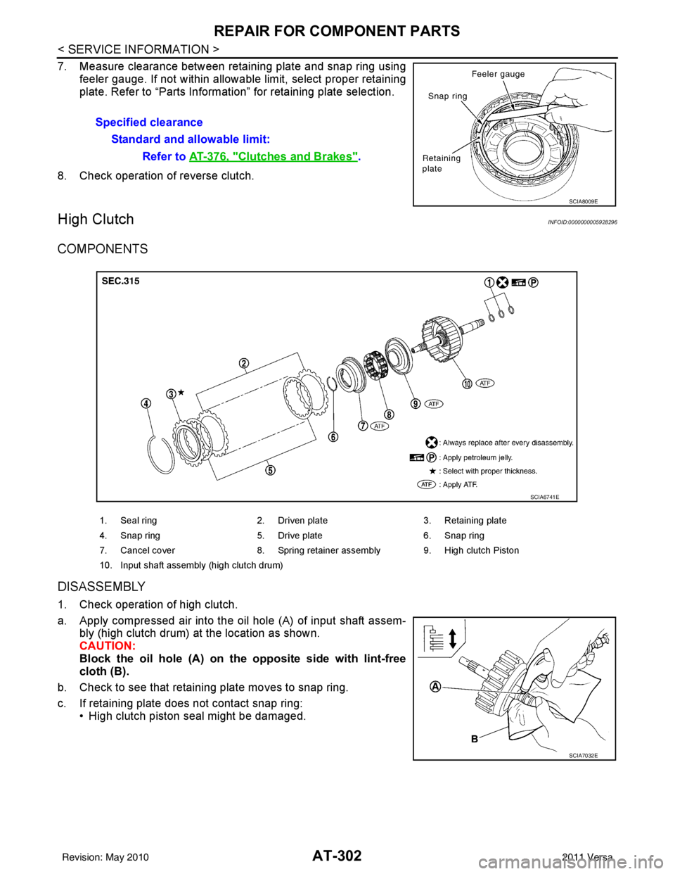
7. Measure clearance between retaining plate and snap ring usingfeeler gauge. If not within allowable limit, select proper retaining
plate. Refer to “Parts Information” for retaining plate selection.
8. Check operation of reverse clutch.
High ClutchINFOID:0000000005928296
COMPONENTS
DISASSEMBLY
1. Check operation of high clutch.
a. Apply compressed air into the oil hole (A) of input shaft assem- bly (high clutch drum) at the location as shown.
CAUTION:
Block the oil hole (A) on the opposite side with lint-free
cloth (B).
b. Check to see that retaining plate moves to snap ring.
c. If retaining plate does not contact snap ring: • High clutch piston seal might be damaged.Specified clearance
Standard and allowable limit: Refer to AT-376, "
Clutches and Brakes".
SCIA8009E
1. Seal ring 2. Driven plate 3. Retaining plate
4. Snap ring 5. Drive plate 6. Snap ring
7. Cancel cover 8. Spring retainer assembly 9. High clutch Piston
10. Input shaft assembly (high clutch drum)
SCIA6741E
SCIA7032E
Revision: May 2010 2011 Versa
Page 320 of 3787

REPAIR FOR COMPONENT PARTSAT-303
< SERVICE INFORMATION >
DE
F
G H
I
J
K L
M A
B
AT
N
O P
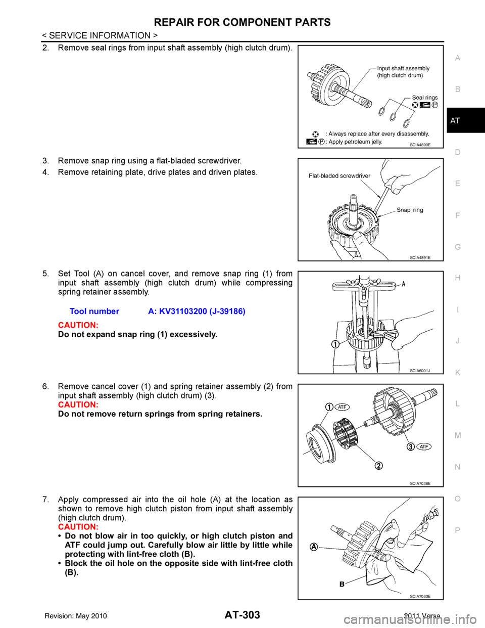
2. Remove seal rings from input shaft assembly (high clutch drum).
3. Remove snap ring using a flat-bladed screwdriver.
4. Remove retaining plate, drive plates and driven plates.
5. Set Tool (A) on cancel cover, and remove snap ring (1) from input shaft assembly (high clutch drum) while compressing
spring retainer assembly.
CAUTION:
Do not expand snap ring (1) excessively.
6. Remove cancel cover (1) and spring retainer assembly (2) from input shaft assembly (high clutch drum) (3).
CAUTION:
Do not remove return springs from spring retainers.
7. Apply compressed air into the oil hole (A) at the location as shown to remove high clutch piston from input shaft assembly
(high clutch drum).
CAUTION:
• Do not blow air in too quickly, or high clutch piston and
ATF could jump out. Carefully blow air little by little while
protecting with lint-free cloth (B).
• Block the oil hole on the oppo site side with lint-free cloth
(B).
SCIA4890E
SCIA4891E
Tool number A: KV31103200 (J-39186)
SCIA6001J
SCIA7036E
SCIA7033E
Revision: May 2010 2011 Versa
Page 338 of 3787
REPAIR FOR COMPONENT PARTSAT-321
< SERVICE INFORMATION >
DE
F
G H
I
J
K L
M A
B
AT
N
O P
1. Install forward one-way clutch on forward clutch hub. CAUTION:
Be careful with the directi on of forward one-way clutch.
2. Install end bearing (2) on forward one-way clutch (3). (1): Forward clutch hub
3. Install thrust washer on rear internal gear. CAUTION:
Align pawls of thrust washer with holes of rear internal
gear.
4. Install end bearing (1) on rear internal gear (2).
5. Install forward clutch hub on rear internal gear. CAUTION:
• Check operation of forward one-way clutch.
Hold rear internal gear and turn forward clutch hub.
Check forward clutch hub for correct locking and unlock-
ing directions.
• If not as shown, check the instal lation direction of forward
one-way clutch.
SAT976H
SCIA7026E
SCIA3690E
SCIA7028E
AAT426
Revision: May 2010 2011 Versa
Page 339 of 3787
AT-322
< SERVICE INFORMATION >
REPAIR FOR COMPONENT PARTS
Output Shaft, Output Gear, Idler Gear, Reduction Pinion Gear and Bearing Retainer
INFOID:0000000005928300
COMPONENTS
HR16DE engine models
SCIA5883J
1. Idler gear 2. Idler gear bearing 3. Reduction pinion gear adjusting
shim
4. Reduction pinion gear bearing 5. Reduction pinion gear 6. Output shaft bearing
7. Seal ring 8. Bearing retainer 9. Output shaft
10. Seal ring 11. Output gear adjusting spacer 12. Output gear bearing
13. Output gear 14. Lock nut
Revision: May 2010 2011 Versa
Page 340 of 3787
REPAIR FOR COMPONENT PARTSAT-323
< SERVICE INFORMATION >
DE
F
G H
I
J
K L
M A
B
AT
N
O P
MR18DE engine models
DISASSEMBLY
1. Remove seal rings (1) from output shaft (2) and bearing retainer (3).
• HR16DE engine models
SCIA7944E
1. Lock nut 2. Idler gear3. Idler gear bearing
4. Reduction pinion gear adjusting shim 5. Reduction pinion gear bearing 6. Reduction pinion gear
7. Seal ring 8. Snap ring9. Radial needle bearing
10. Bearing retainer 11. Thrust needle bearing 12. Seal ring
13. Output shaft 14. Output shaft bearing15. Output shaft adjusting shim
JPDIA0288ZZ
Revision: May 2010 2011 Versa
Page 348 of 3787
REPAIR FOR COMPONENT PARTSAT-331
< SERVICE INFORMATION >
DE
F
G H
I
J
K L
M A
B
AT
N
O P
• MR18DE engine models
CAUTION:
Roll paper around seal ring s to prevent seal rings from
spreading.
Band Servo Piston AssemblyINFOID:0000000005928301
COMPONENTS
HR16DE engine models
SCIA7996E
SCIA8011E
SCIA5891J
1. Lock nut 2. Anchor end pin 3. O-ring
4. Servo piston retainer 5. D-ring 6. OD servo piston
7. O-ring 8. Snap ring 9. OD servo piston retainer
10. E-ring 11. Spring retainer 12. OD servo return spring
13. D-ring 14. Band servo piston 15. Band servo thrust washer
16. Band servo piston stem 17. 2nd servo return spring
Revision: May 2010 2011 Versa
Page 349 of 3787

AT-332
< SERVICE INFORMATION >
REPAIR FOR COMPONENT PARTS
MR18DE engine models
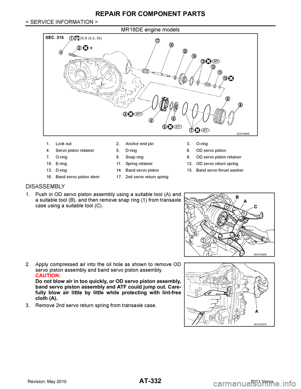
DISASSEMBLY
1. Push in OD servo piston assembly using a suitable tool (A) anda suitable tool (B), and then remove snap ring (1) from transaxle
case using a suitable tool (C).
2. Apply compressed air into the oil hole as shown to remove OD servo piston assembly and band servo piston assembly.
CAUTION:
Do not blow air in too quickly, or OD servo piston assembly,
band servo piston assembly and ATF could jump out. Care-
fully blow air little by little while protecting with lint-free
cloth (A).
3. Remove 2nd servo return spring from transaxle case.
SCIA7965E
1. Lock nut 2. Anchor end pin 3. O-ring
4. Servo piston retainer 5. D-ring 6. OD servo piston
7. O-ring 8. Snap ring 9. OD servo piston retainer
10. E-ring 11. Spring retainer 12. OD servo return spring
13. D-ring 14. Band servo piston 15. Band servo thrust washer
16. Band servo piston stem 17. 2nd servo return spring
SCIA7050E
SCIA7051E
Revision: May 2010 2011 Versa
Page 350 of 3787

REPAIR FOR COMPONENT PARTSAT-333
< SERVICE INFORMATION >
DE
F
G H
I
J
K L
M A
B
AT
N
O P
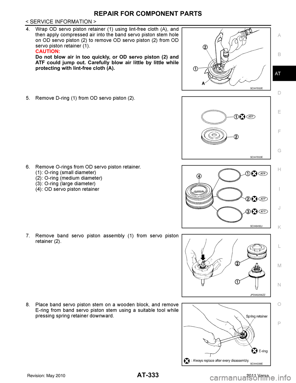
4. Wrap OD servo piston retainer (1) using lint-free cloth (A), and then apply compressed air into the band servo piston stem hole
on OD servo piston (2) to remove OD servo piston (2) from OD
servo piston retainer (1).
CAUTION:
Do not blow air in too quickly, or OD servo piston (2) and
ATF could jump out. Carefully blow air little by little while
protecting with lint-free cloth (A).
5. Remove D-ring (1) from OD servo piston (2).
6. Remove O-rings from OD servo piston retainer. (1): O-ring (small diameter)
(2): O-ring (medium diameter)
(3): O-ring (large diameter)
(4): OD servo piston retainer
7. Remove band servo piston assembly (1) from servo piston retainer (2).
8. Place band servo piston stem on a wooden block, and remove E-ring from band servo piston stem using a suitable tool while
pressing spring retainer downward.
SCIA7052E
SCIA7053E
SCIA6492J
JPDIA0256ZZ
SCIA4336E
Revision: May 2010 2011 Versa