Page 352 of 3787
REPAIR FOR COMPONENT PARTSAT-335
< SERVICE INFORMATION >
DE
F
G H
I
J
K L
M A
B
AT
N
O P
• Check each return spring for damage or deformation. Also mea- sure free length. Refer to AT-378, "
Band Servo".
• Replace springs if deformed or fatigued.
ASSEMBLY
1. Install D-rings to band servo piston.
2. Install band servo thrust washer (4), band servo piston (3), OD servo return spring (2) and spring retainer (1) to band servo pis-
ton stem (5).
3. Place band servo piston stem (1) on a wooden block, and install E-ring (2) to band servo piston stem (1) while pressing spring
retainer (3) downward.
4. Install O-ring to servo piston retainer.
SAT138D
SCIA3688E
SCIA7054E
SCIA7056E
Revision: May 2010 2011 Versa
Page 355 of 3787
AT-338
< SERVICE INFORMATION >
REPAIR FOR COMPONENT PARTS
HR16DE engine modelsMR18DE models
DISASSEMBLY
SCIA7486E
1. Pinion mate gear thrust washer 2. Pinion mate gear 3. Pinion mate shaft
4. Side gear 5. Side gear thrust washer 6. Lock pin
7. Differential side bearing 8. Speedometer drive gear 9. Differential case
10. Final gear 11. Differential side bearing adjusting shim
SCIA7962E
1. Pinion mate gear 2. Pinion mate gear thrust washer 3. Pinion mate shaft
4. Lock pin 5. Side gear 6. Side gear thrust washer
7. Differential side bearing 8. Speedometer drive gear 9. Differential case
10. Final gear 11. Differential side bearing 12. Differential side bearing adjusting shim
Revision: May 2010 2011 Versa
Page 357 of 3787
AT-340
< SERVICE INFORMATION >
REPAIR FOR COMPONENT PARTS
3. Remove speedometer drive gear from differential case.
4. Drive out lock pin from differential case (1) using Tool (A).
5. Draw out pinion mate shaft.
6. Remove pinion mate gears, pinion mate gear thrust washers,side gears and side gear thrust washers.
INSPECTION
Gears, Washers, Pinion Mate Shaft and Differential Case
• Check mating surfaces of differential case, side gears, pinion mate
gears and pinion mate shaft. Replace if necessary.
• Check washers for wear. Replace if necessary.
Bearings
SAT313D
Tool number : KV32101000 (J-25689-A)
SCIA7034E
SAT316D
SAT544F
Revision: May 2010 2011 Versa
Page 359 of 3787
AT-342
< SERVICE INFORMATION >
REPAIR FOR COMPONENT PARTS
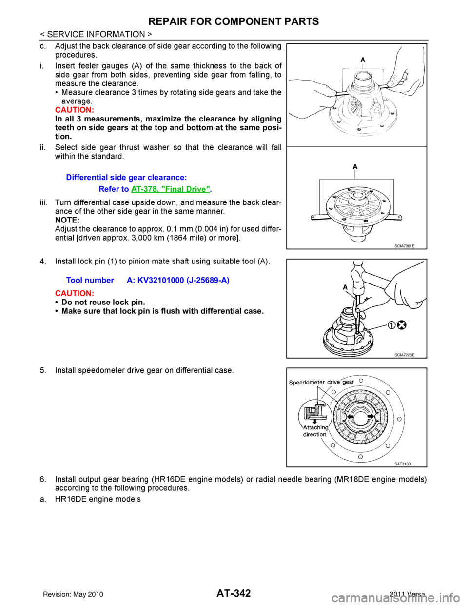
c. Adjust the back clearance of side gear according to the followingprocedures.
i. Insert feeler gauges (A) of the same thickness to the back of side gear from both sides, preventing side gear from falling, to
measure the clearance.
• Measure clearance 3 times by rotating side gears and take theaverage.
CAUTION:
In all 3 measurements, maximi ze the clearance by aligning
teeth on side gears at the top and bottom at the same posi-
tion.
ii. Select side gear thrust washer so that the clearance will fall within the standard.
iii. Turn differential case upside down, and measure the back clear- ance of the other side gear in the same manner.
NOTE:
Adjust the clearance to approx. 0.1 mm (0.004 in) for used differ-
ential [driven approx. 3,000 km (1864 mile) or more].
4. Install lock pin (1) to pinion mate shaft using suitable tool (A).
CAUTION:
• Do not reuse lock pin.
• Make sure that lock pin is flush with differential case.
5. Install speedometer drive gear on differential case.
6. Install output gear bearing (HR16DE engine models) or radial needle bearing (MR18DE engine models) according to the following procedures.
a. HR16DE engine models Differential side gear clearance:
Refer to AT-378, "
Final Drive".
SCIA7061E
Tool number A: KV32101000 (J-25689-A)
SCIA7228E
SAT313D
Revision: May 2010 2011 Versa
Page 363 of 3787
AT-346
< SERVICE INFORMATION >
ASSEMBLY
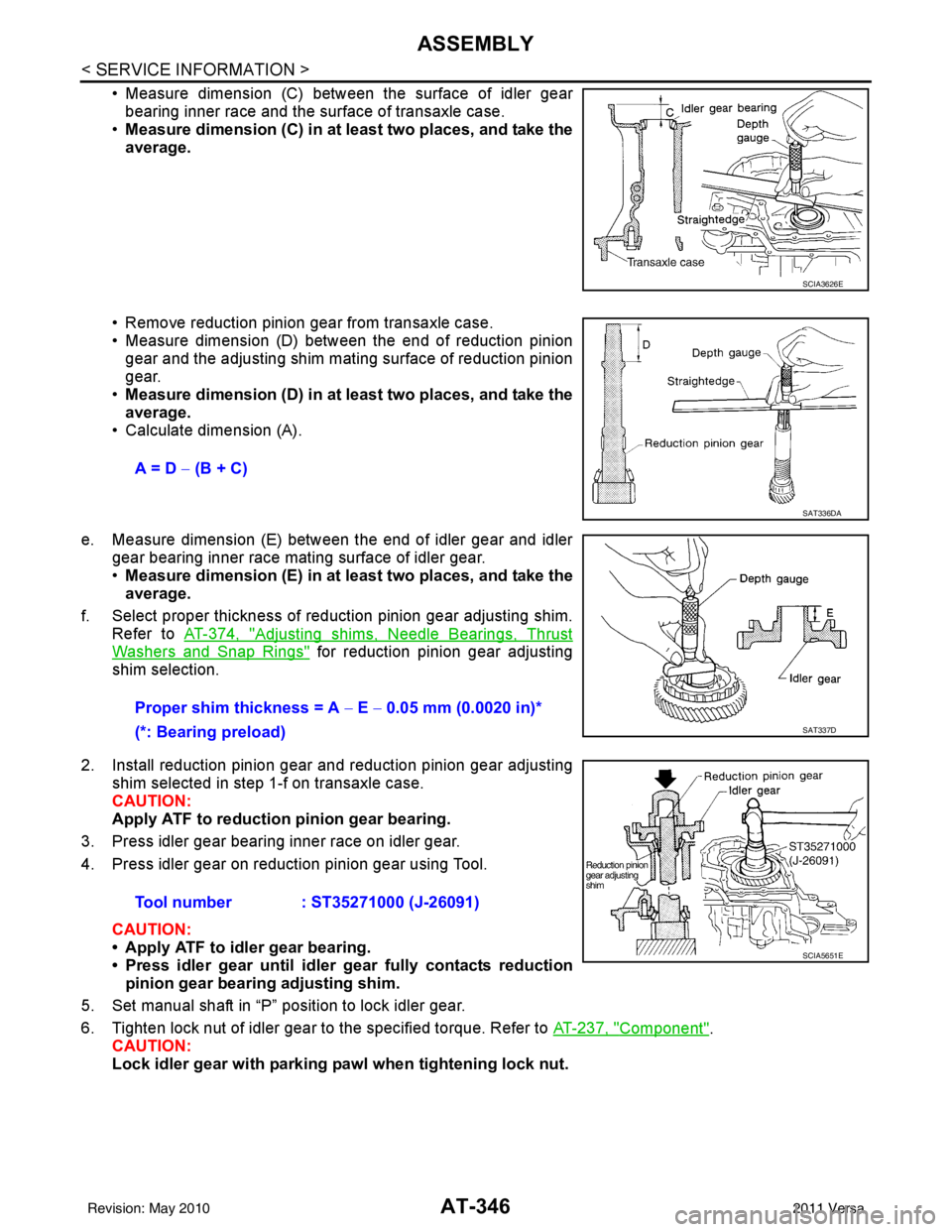
• Measure dimension (C) between the surface of idler gearbearing inner race and the surface of transaxle case.
• Measure dimension (C) in at least two places, and take the
average.
• Remove reduction pinion gear from transaxle case.
• Measure dimension (D) between the end of reduction pinion gear and the adjusting shim mating surface of reduction pinion
gear.
• Measure dimension (D) in at least two places, and take the
average.
• Calculate dimension (A).
e. Measure dimension (E) between the end of idler gear and idler gear bearing inner race mating surface of idler gear.
•Measure dimension (E) in at least two places, and take the
average.
f. Select proper thickness of reduction pinion gear adjusting shim. Refer to AT-374, "
Adjusting shims, Needle Bearings, Thrust
Washers and Snap Rings" for reduction pinion gear adjusting
shim selection.
2. Install reduction pinion gear and reduction pinion gear adjusting shim selected in step 1-f on transaxle case.
CAUTION:
Apply ATF to reduction pinion gear bearing.
3. Press idler gear bearing inner race on idler gear.
4. Press idler gear on reduction pinion gear using Tool.
CAUTION:
• Apply ATF to idler gear bearing.
• Press idler gear until idler gear fully contacts reduction
pinion gear bearing adjusting shim.
5. Set manual shaft in “P” position to lock idler gear.
6. Tighten lock nut of idler gear to the specified torque. Refer to AT-237, "
Component".
CAUTION:
Lock idler gear with parking pawl when tightening lock nut.
SCIA3626E
A = D − (B + C)
SAT336DA
Proper shim thickness = A − E − 0.05 mm (0.0020 in)*
(*: Bearing preload)
SAT337D
Tool number : ST35271000 (J-26091)
SCIA5651E
Revision: May 2010 2011 Versa
Page 365 of 3787
AT-348
< SERVICE INFORMATION >
ASSEMBLY
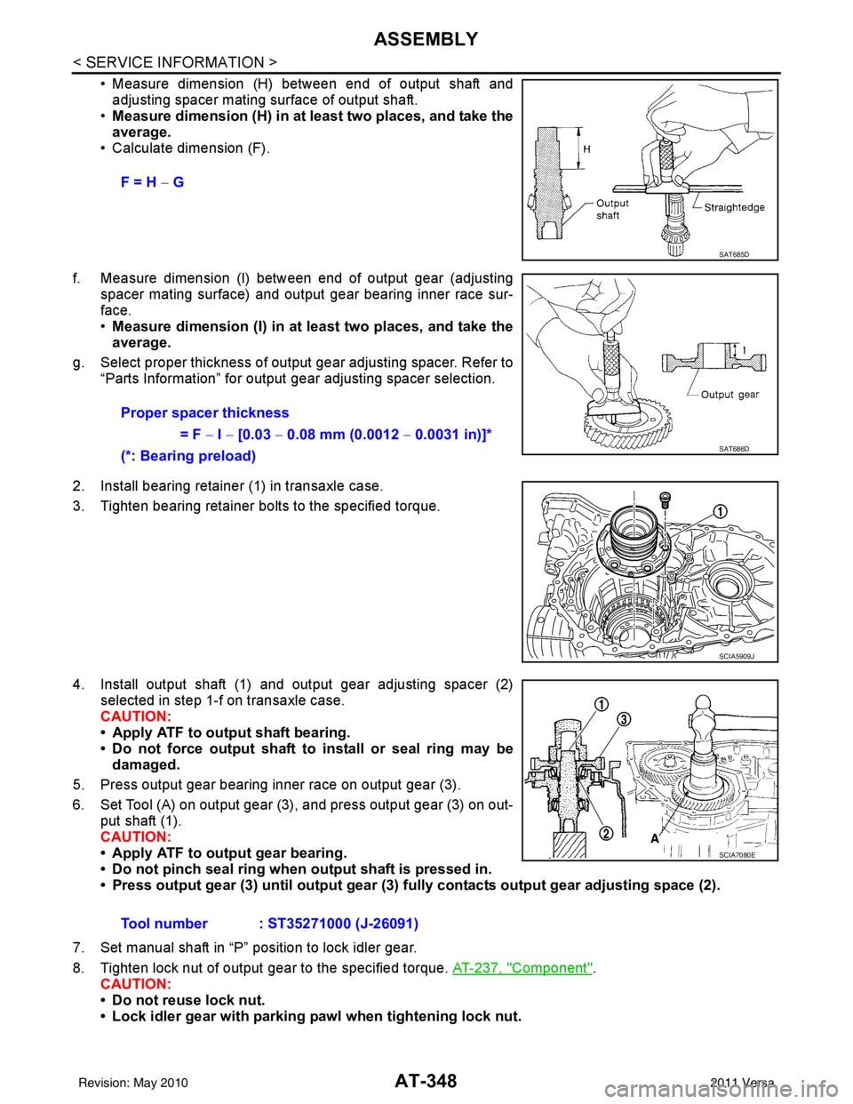
• Measure dimension (H) between end of output shaft andadjusting spacer mating surface of output shaft.
• Measure dimension (H) in at least two places, and take the
average.
• Calculate dimension (F).
f. Measure dimension (I) between end of output gear (adjusting spacer mating surface) and output gear bearing inner race sur-
face.
•Measure dimension (I) in at least two places, and take the
average.
g. Select proper thickness of output gear adjusting spacer. Refer to “Parts Information” for output gear adjusting spacer selection.
2. Install bearing retainer (1) in transaxle case.
3. Tighten bearing retainer bolts to the specified torque.
4. Install output shaft (1) and output gear adjusting spacer (2) selected in step 1-f on transaxle case.
CAUTION:
• Apply ATF to output shaft bearing.
• Do not force output shaft to install or seal ring may be
damaged.
5. Press output gear bearing inner race on output gear (3).
6. Set Tool (A) on output gear (3), and press output gear (3) on out- put shaft (1).
CAUTION:
• Apply ATF to output gear bearing.
• Do not pinch seal ring when output shaft is pressed in.
• Press output gear (3) until output gear (3) fully contacts output gear adjusting space (2).
7. Set manual shaft in “P” position to lock idler gear.
8. Tighten lock nut of output gear to the specified torque. AT-237, "
Component".
CAUTION:
• Do not reuse lock nut.
• Lock idler gear with parking pawl when tightening lock nut. F = H −
G
SAT685D
Proper spacer thickness
= F − I − [0.03 − 0.08 mm (0.0012 − 0.0031 in)]*
(*: Bearing preload)
SAT686D
SCIA5909J
Tool number : ST35271000 (J-26091)
SCIA7080E
Revision: May 2010 2011 Versa
Page 366 of 3787
ASSEMBLYAT-349
< SERVICE INFORMATION >
DE
F
G H
I
J
K L
M A
B
AT
N
O P
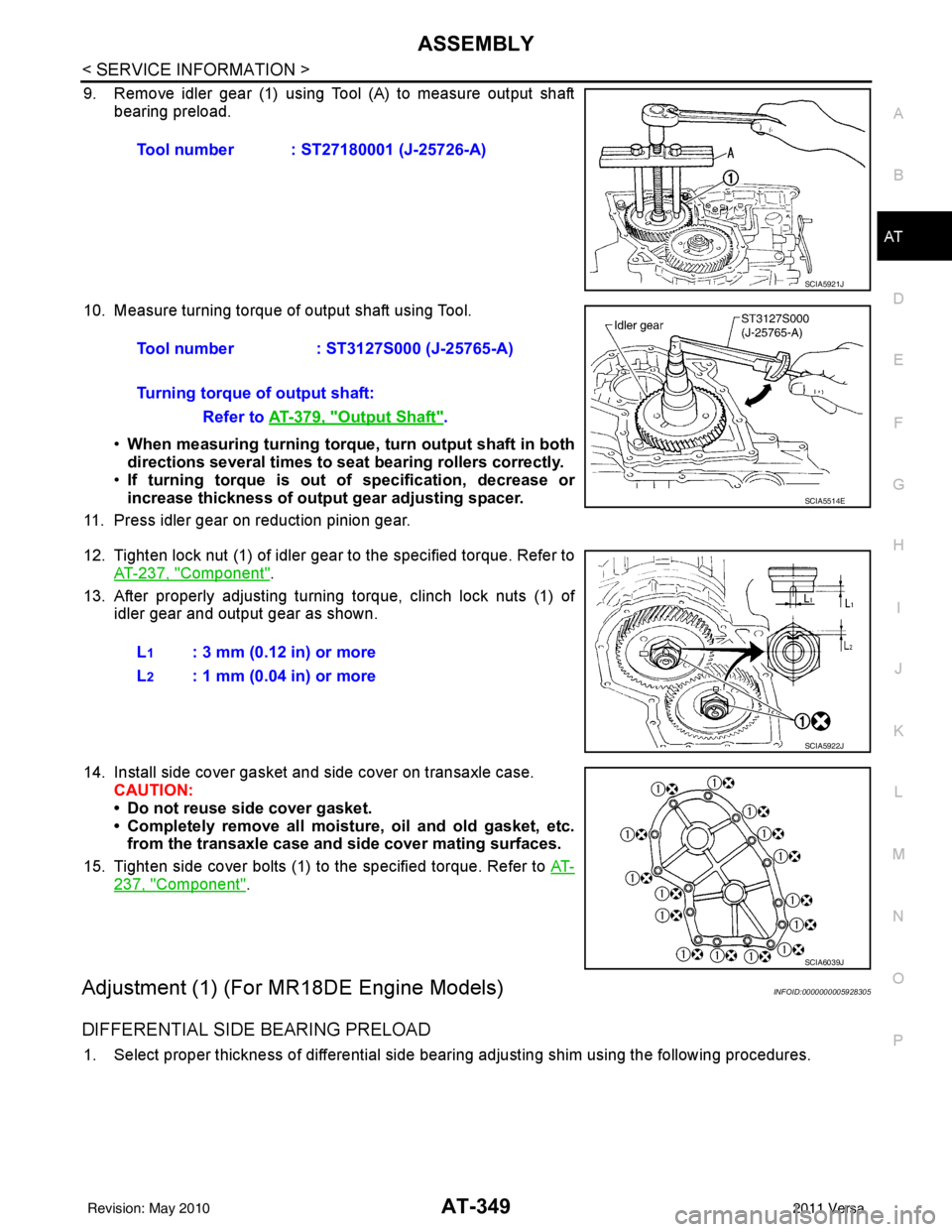
9. Remove idler gear (1) using Tool (A) to measure output shaft bearing preload.
10. Measure turning torque of output shaft using Tool. •When measuring turning torque , turn output shaft in both
directions several times to seat bearing rollers correctly.
• If turning torque is out of specification, decrease or
increase thickness of output gear adjusting spacer.
11. Press idler gear on reduction pinion gear.
12. Tighten lock nut (1) of idler gear to the specified torque. Refer to AT-237, "
Component".
13. After properly adjusting turning torque, clinch lock nuts (1) of idler gear and output gear as shown.
14. Install side cover gasket and side cover on transaxle case. CAUTION:
• Do not reuse side cover gasket.
• Completely remove all moistu re, oil and old gasket, etc.
from the transaxle case and side cover mating surfaces.
15. Tighten side cover bolts (1) to the specified torque. Refer to AT-
237, "Component".
Adjustment (1) (For MR18DE Engine Models)INFOID:0000000005928305
DIFFERENTIAL SIDE BEARING PRELOAD
1. Select proper thickness of differential side bearing adjusting shim using the following procedures.Tool number : ST27180001 (J-25726-A)
SCIA5921J
Tool number
: ST3127S000 (J-25765-A)
Turning torque of output shaft: Refer to AT-379, "
Output Shaft".
SCIA5514E
L1: 3 mm (0.12 in) or more
L
2: 1 mm (0.04 in) or more
SCIA5922J
SCIA6039J
Revision: May 2010 2011 Versa
Page 369 of 3787
AT-352
< SERVICE INFORMATION >
ASSEMBLY
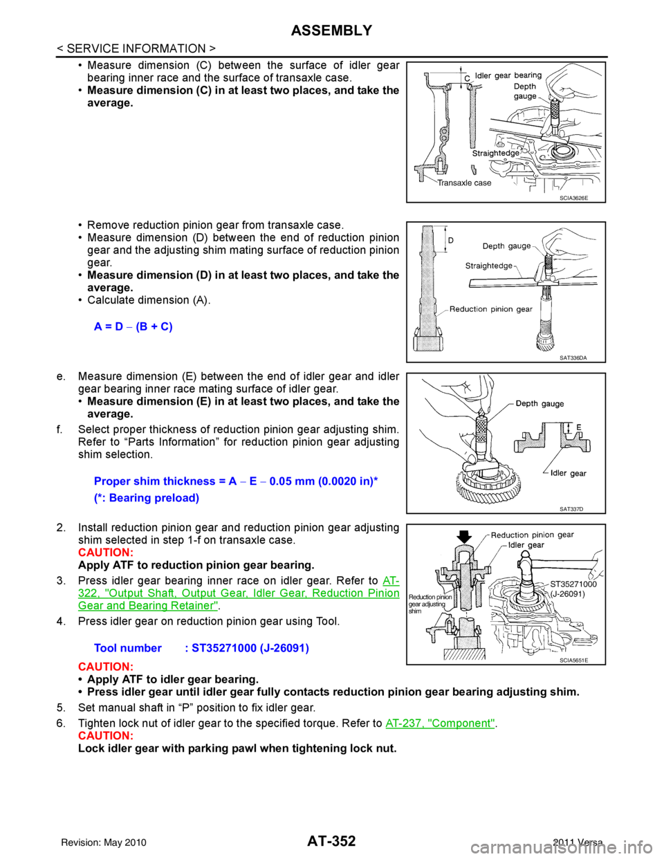
• Measure dimension (C) between the surface of idler gearbearing inner race and the surface of transaxle case.
• Measure dimension (C) in at least two places, and take the
average.
• Remove reduction pinion gear from transaxle case.
• Measure dimension (D) between the end of reduction pinion gear and the adjusting shim mating surface of reduction pinion
gear.
• Measure dimension (D) in at least two places, and take the
average.
• Calculate dimension (A).
e. Measure dimension (E) between the end of idler gear and idler gear bearing inner race mating surface of idler gear.
•Measure dimension (E) in at least two places, and take the
average.
f. Select proper thickness of reduction pinion gear adjusting shim. Refer to “Parts Information” for reduction pinion gear adjusting
shim selection.
2. Install reduction pinion gear and reduction pinion gear adjusting shim selected in step 1-f on transaxle case.
CAUTION:
Apply ATF to reduction pinion gear bearing.
3. Press idler gear bearing inner race on idler gear. Refer to AT-
322, "Output Shaft, Output Gear, Idler Gear, Reduction Pinion
Gear and Bearing Retainer".
4. Press idler gear on reduction pinion gear using Tool.
CAUTION:
• Apply ATF to idler gear bearing.
• Press idler gear until idler gear fully contacts reduction pinion gear bearing adjusting shim.
5. Set manual shaft in “P” position to fix idler gear.
6. Tighten lock nut of idler gear to the specified torque. Refer to AT-237, "
Component".
CAUTION:
Lock idler gear with parking pawl when tightening lock nut.
SCIA3626E
A = D − (B + C)
SAT336DA
Proper shim thickness = A − E − 0.05 mm (0.0020 in)*
(*: Bearing preload)
SAT337D
Tool number : ST35271000 (J-26091)SCIA5651E
Revision: May 2010 2011 Versa