Page 3762 of 3787

WW-16
< SERVICE INFORMATION >
FRONT WIPER AND WASHER SYSTEM
3. Start auto active test. Refer to PG-20, "Auto Active Test" .
4. Check voltage between IPDM E/R connector and ground while front wiper (HI, LO) is operating.
OK or NG
OK >> Replace front wiper motor. Refer to WW-22, "Removal and Installation of Front Wiper Drive
Assembly" .
NG >> Replace IPDM E/R. Refer to PG-28, "
Removal and Installation of IPDM E/R" .
Front Wiper Does Not Return to Stop Positi on (After Front Wiper Operates for 10 Sec-
onds, They Stop for 20 Second s, and After Repeating the Operation Five Times, They
Become Inoperative)
INFOID:0000000005929218
CAUTION:
• When auto-stop signal has not varied for 10 seconds or longer while IPDM E/R is operating front wip-
ers, IPDM E/R considers that front wipers are locked, and stops wiper output. That causes this symp-
tom.
• This status can be checked by “DATA MONITOR” of “IPDM E/R” on which “WIPER PROT” item
shows “BLOCK”.
1.CHECK FRONT WIPER STOP SIGNAL
With CONSULT-lIl
Select “IPDM E/R” on CONSULT-III. With “DATA MONITOR”, make sure that “WIP AUTO STOP” turns “ACT
P” - “STOP P” linked with wiper operation.
Without CONSULT-llI
GO TO 2.
OK or NG
OK >> Replace IPDM E/R. Refer to PG-28, "Removal and Installation of IPDM E/R" .
NG >> GO TO 2.
2.CHECK IPDM E/R
1. Turn ignition switch ON.
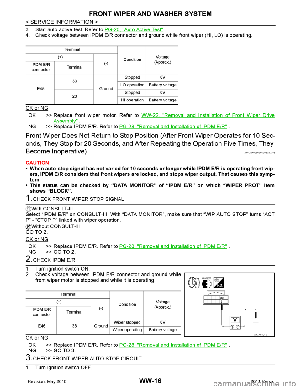
2. Check voltage between IPDM E/R connector and ground while front wiper motor is stopped and while it is operating.
OK or NG
OK >> Replace IPDM E/R. Refer to PG-28, "Removal and Installation of IPDM E/R" .
NG >> GO TO 3.
3.CHECK FRONT WIPER AUTO STOP CIRCUIT
1. Turn ignition switch OFF.
Te r m i n a l
ConditionVo l ta g e
(Approx.)
(+)
(-)
IPDM E/R
connector Te r m i n a l
E45 33
GroundStopped 0V
LO operation Battery voltage
23 Stopped 0V
HI operation Battery voltage
Te r m i n a l
ConditionVo l ta g e
(Approx.)
(+)
(-)
IPDM E/R
connector Te r m i n a l
E46 38 Ground Wiper stopped 0V
Wiper operating Battery voltage
WKIA5491E
Revision: May 2010 2011 Versa
Page 3773 of 3787

REAR WIPER AND WASHER SYSTEMWW-27
< SERVICE INFORMATION >
C
DE
F
G H
I
J
L
M A
B
WW
N
O P
REAR WIPER AND WASHER SYSTEM
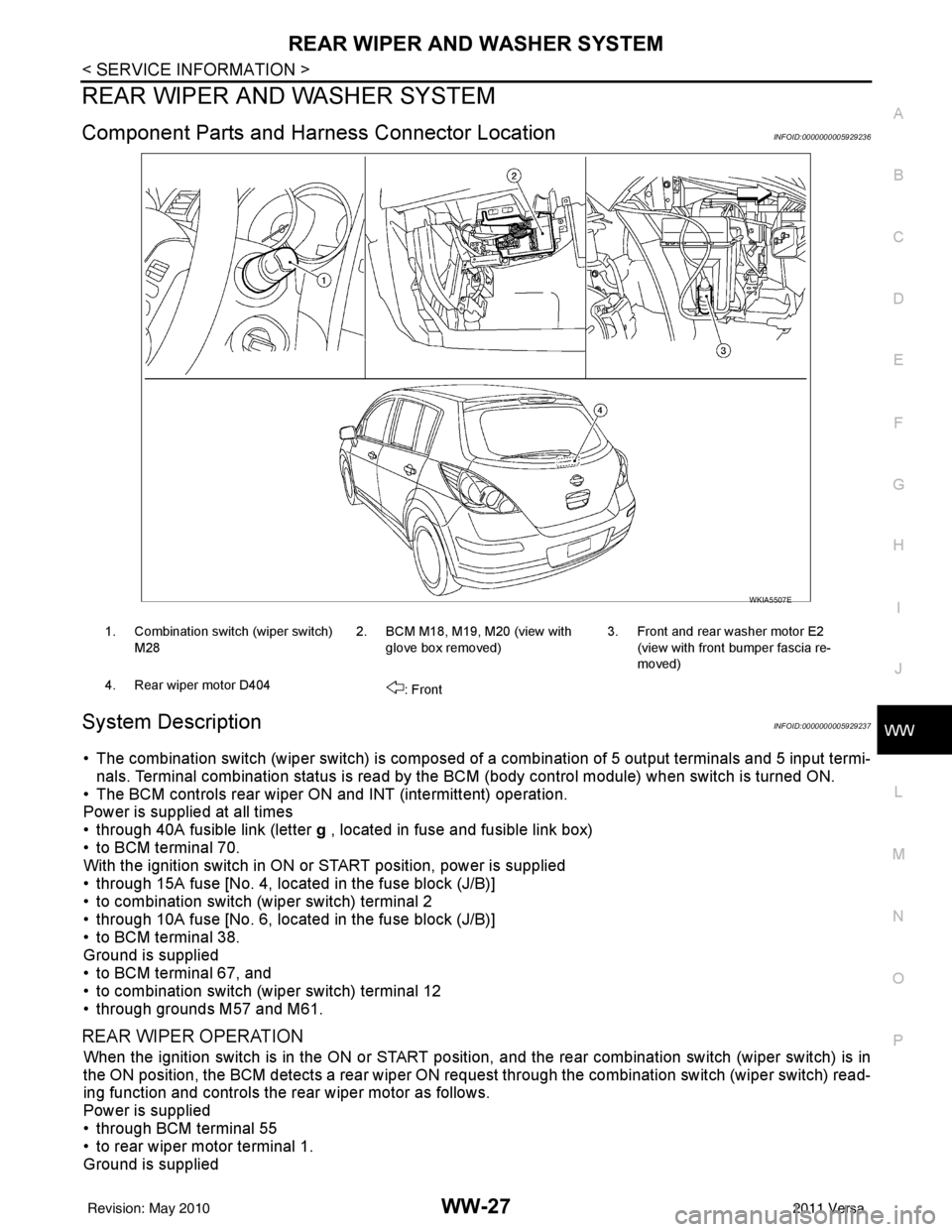
Component Parts and Har ness Connector LocationINFOID:0000000005929236
System DescriptionINFOID:0000000005929237
• The combination switch (wiper switch) is composed of a combination of 5 output terminals and 5 input termi-
nals. Terminal combination status is read by the BCM (body control module) when switch is turned ON.
• The BCM controls rear wiper ON and INT (intermittent) operation.
Power is supplied at all times
• through 40A fusible link (letter g , located in fuse and fusible link box)
• to BCM terminal 70.
With the ignition switch in ON or START position, power is supplied
• through 15A fuse [No. 4, located in the fuse block (J/B)]
• to combination switch (wiper switch) terminal 2
• through 10A fuse [No. 6, located in the fuse block (J/B)]
• to BCM terminal 38.
Ground is supplied
• to BCM terminal 67, and
• to combination switch (wiper switch) terminal 12
• through grounds M57 and M61.
REAR WIPER OPERATION
When the ignition switch is in the ON or START position, and the rear combination switch (wiper switch) is in
the ON position, the BCM detects a rear wiper ON r equest through the combination switch (wiper switch) read-
ing function and controls the rear wiper motor as follows.
Power is supplied
• through BCM terminal 55
• to rear wiper motor terminal 1.
Ground is supplied
WKIA5507E
1. Combination switch (wiper switch)
M28 2. BCM M18, M19, M20 (view with
glove box removed) 3. Front and rear washer motor E2
(view with front bumper fascia re-
moved)
4. Rear wiper motor D404 : Front
Revision: May 2010 2011 Versa
Page 3774 of 3787

WW-28
< SERVICE INFORMATION >
REAR WIPER AND WASHER SYSTEM
• to rear wiper motor terminal 3
• through grounds B117, B132 and D402.
With power and ground supplied, the rear wiper motor operates.
INTERMITTENT OPERATION
The rear wiper motor operates the wiper arm at low speed approximately every 7 seconds.
When the combination switch (wiper switch) is in the r ear wiper INT position, the BCM detects a rear wiper INT
request through the combination switch (wiper switch) reading function.
When BCM operates rear wiper motor, power is supplied
• through BCM terminal 55
• to rear wiper motor terminal 1.
Ground is supplied
• to rear wiper motor terminal 3
• through grounds B117, B132 and D402.
With power and ground supplied, the rear wiper operates in intermittent mode.
AUTO STOP OPERATION
When the rear wiper arm is not located at the base of the rear window, and the rear combination switch (wiper
switch) is turned OFF, the rear wiper motor will continue to operate until the rear wiper arm is at the base of the
rear window. When the rear wiper arm reaches the bas e, rear wiper motor terminals 2 and 1 are connected.
Ground is supplied
• to BCM terminal 44
• through rear wiper motor terminal 2, and
• through rear wiper motor terminal 3, and
• through grounds B117, B132 and D402.
REAR WASHER OPERATION
When the ignition switch is in the ON or START positi on, and the front and rear washer switches are OFF, the
front and rear washer motor is supplied power
• through 15A fuse [No. 4, located in the fuse block (J/B)]
• to combination switch (wiper switch) terminal 14
• through combination switch (wiper switch) terminal 11
• to front and rear washer motor terminal 2.
When the rear combination switch (wiper switch) is in rear washer position, the BCM detects a rear washer
signal by BCM combination switch (wiper switch) readi ng function. Combination switch (wiper switch) ground
is supplied
• to front and rear washer motor terminal 1
• through combination switch (wiper switch) terminal 13, and
• through combination switch (wiper switch) terminal 12
• through grounds M57 and M61.
With ground supplied, the front and rear washer motor is operated in the rear direction.
When the BCM detects that the rear washer motor has operated for 0.4 seconds or longer, BCM operates the
rear wiper motor.
When the BCM detects that the rear washer switch is in OFF, the rear wiper motor cycles approximately 3
times and then stops.
If the rear washer is operated with the rear combinati on switch (wiper switch) in the INT position, normal rear
wiper operation will take over. Once the rear washer switch is released the rear wiper will return to INT opera-
tion.
BCM Combination Switch (Wiper Switch) Reading Function
Refer to BCS-4, "System Description" .
Revision: May 2010 2011 Versa