2011 NISSAN LATIO hatch back
[x] Cancel search: hatch backPage 3034 of 3787

LT-2
System Description .................................................50
CAN Communication System Description ..............52
Schematic ............................................................ ...53
Wiring Diagram - TURN - ........................................54
Terminal and Reference Value for BCM .................57
How to Proceed with Trouble Diagnosis .................57
Preliminary Check ..................................................58
CONSULT-III Function (BCM) ................................58
Turn Signals Do Not Operate .................................58
Front Turn Signal Lamp Does Not Operate ............58
Rear Turn Signal Lamp Does Not Operate ............59
Hazard Warning Lamp Does Not Operate But
Turn Signal Lamp Operates ...................................
60
Turn Signal Indicator Lamp Does Not Operate ......61
Bulb Replacement for Front Turn Signal Lamp ......61
Bulb Replacement for Rear Turn Signal Lamp .......61
Removal and Installation of Front Turn Signal
Lamp .......................................................................
61
Removal and Installation of Rear Turn Signal
Lamp .......................................................................
61
LIGHTING AND TURN SIGNAL SWITCH .........62
Removal and Installation ..................................... ...62
HAZARD SWITCH .............................................63
Removal and Installation ..................................... ...63
COMBINATION SWITCH ..................................64
Wiring Diagram - COMBSW - .............................. ...64
Combination Switch Reading Function ...................64
Terminal and Reference Value for BCM .................65
CONSULT-III Function (BCM) ................................65
Combination Switch Inspection ..............................65
Removal and Installation ..................................... ...67
STOP LAMP ......................................................68
Wiring Diagram - STOP/L .................................... ...68
Wiring Diagram - STOP/L .......................................69
Bulb Replacement (High-Mounted Stop Lamp) ......69
Bulb Replacement (Rear Combination Lamp) ........70
Removal and Installation (High-Mounted Stop
Lamp) .....................................................................
70
Removal and Installation (Rear Combination
Lamp) .................................................................. ...
71
BACK-UP LAMP ................................................72
Wiring Diagram - BACK/L - .................................. ...72
Bulb Replacement ..................................................72
Removal and Installation ........................................73
PARKING, LICENSE PLATE AND TAIL
LAMPS ...............................................................
74
Component Parts and Harness Connector Loca-
tion ....................................................................... ...
74
System Description .................................................74
CAN Communication System Description ........... ...75
Schematic ...............................................................76
Wiring Diagram - TAIL/L - .......................................77
Terminal and Reference Value for BCM .............. ...80
Terminal and Reference Value for IPDM E/R .........80
How to Proceed with Trouble Diagnosis .................81
Preliminary Check ...................................................81
CONSULT-III Function (BCM) ............................. ...81
CONSULT-III Function (IPDM E/R) ........................81
Parking, License Plate and Tail Lamps Do Not Il-
luminate ..................................................................
81
Parking, License Plate and Tail Lamps Do Not
Turn OFF (After Approx. 10 Minutes) .....................
84
Bulb Replacement ................................................ ...84
Removal and Installation .........................................85
REAR COMBINATION LAMP ........................ ...87
Component .......................................................... ...87
Bulb Replacement ...................................................87
Removal and Installation .........................................88
Disassembly and Assembly ................................. ...88
INTERIOR LAMP ...............................................90
Map Lamp ............................................................ ...90
Luggage Room Lamp, Hatch Back .........................90
Trunk Room Lamp, Sedan ......................................91
Vanity Mirror Lamp ..................................................91
INTERIOR ROOM LAMP ...................................93
Component Parts and Harness Connector Loca-
tion ....................................................................... ...
93
System Description .................................................93
Schematic ...............................................................97
Wiring Diagram - INT/L - .........................................98
Terminal and Reference Value for BCM ...............102
How to Proceed with Trouble Diagnosis ...............102
Preliminary Check .................................................103
CONSULT-III Function (BCM) ............................. .103
Interior Room Lamp Control Does Not Operate
(With Map Lamp) ..................................................
104
Interior Room Lamp Control Does Not Operate
(Without Map Lamp) .............................................
106
Bulb Replacement .................................................107
Removal and Installation .......................................108
ILLUMINATION .............................................. ..109
System Description .............................................. .109
CAN Communication System Description ............110
Schematic .............................................................111
Wiring Diagram - ILL - ...........................................112
BULB SPECIFICATIONS ............................... ..116
Headlamp ............................................................. .116
Exterior Lamp ........................................................116
Interior Lamp/Illumination .....................................
Revision: May 2010 2011 Versa
Page 3083 of 3787
TURN SIGNAL AND HAZARD WARNING LAMPSLT-51
< SERVICE INFORMATION >
C
DE
F
G H
I
J
L
M A
B
LT
N
O P
• through grounds B7 and B19.
The BCM also sends a request, via the CAN communication lines, to the combination meter to flash the left
turn signal indicator. The unified meter control unit in the combination meter supplies ground to the \
left turn
signal indicator lamp and activates the audible turn signal indicator.
With power, ground and input supplied, the BCM controls the flashing of the turn signal lamps.
RH Turn Signal Lamp
When turn signal switch is moved to the right turn position, the BCM receives an input signal requesting right
turn signals to flash. The BCM then supplies power
• through BCM terminal 61
• to front combination lamp RH terminal 4 and
• to rear combination lamp RH terminal 6.
Ground is supplied
• to front combination lamp RH terminal 5
• through grounds E15 and E24,
• to rear combination lamp RH terminal 1
• through grounds B117, B132 (all models) and D402 (with hatchback).
The BCM also sends a request, via the CAN communication lines, to the combination meter to flash the right
turn signal indicator. The unified meter control unit in the combination meter supplies ground to the right turn
signal indicator lamp and activates the audible turn signal indicator.
With power, ground and input supplied, the BCM controls the flashing of the turn signal lamps.
HAZARD LAMP OPERATION
Power is supplied at all times
• through 40A fusible link (letter g , located in fuse, fusible link and relay box)
• to BCM terminal 70,
• through 10A fuse [No. 8, located in fuse block (J/B)]
• to BCM terminal 57,
• through 10A fuse [No. 13, located in fuse block (J/B)]
• to combination meter terminal 27.
Ground is supplied
• to hazard switch terminal 1,
• to BCM terminal 67, and
• to combination meter terminals 21, 22 and 23
• through grounds M57 and M61.
When hazard switch is depressed, ground is supplied
• through hazard switch terminal 2
• to BCM terminal 29.
BCM then supplies power
• to front combination lamp LH terminal 4 and
• to rear combination lamp LH terminal 6
• through BCM terminal 60,
• to front combination lamp RH terminal 4 and
• to rear combination lamp RH terminal 6
• through BCM terminal 61.
Ground is supplied
• to front combination lamp LH and RH terminal 5
• through grounds E15 and E24,
• to rear combination lamp LH terminal 1
• through grounds B7 and B19,
• to rear combination lamp RH terminal 1
• through grounds B117, B132 and D402 (hatchback).
The BCM also supplies input to combination meter ac ross the CAN communication lines. This input is pro-
cessed by unified meter control unit in combination mete r, which in turn supplies ground to the left and right
turn signal indicator lamps.
With power and input supplied, BCM controls flashing of hazard warning lamps.
REMOTE KEYLESS ENTRY SYSTEM OPERATION
Power is supplied at all times
• through 40A fusible link (letter g , located in fuse, fusible link and relay box)
• to BCM terminal 70,
• through 10A fuse [No. 13, located in fuse block (J/B)]
Revision: May 2010 2011 Versa
Page 3084 of 3787
LT-52
< SERVICE INFORMATION >
TURN SIGNAL AND HAZARD WARNING LAMPS
• to combination meter terminal 27.
Ground is supplied
• to BCM terminal 67 and
• to combination meter terminals 21, 22 and 23
• through grounds M57 and M61.
When the remote keyless entry system is triggered by input from the keyfob, the BCM supplies power
• through BCM terminal 60
• to front combination lamp LH terminal 4 and
• to rear combination lamp LH terminal 6,
• through BCM terminal 61
• to front turn signal lamp RH terminal 4 and
• to rear combination lamp RH terminal 6.
Ground is supplied
• to front combination lamp LH and RH terminals 5
• through grounds E15 and E24,
• to rear combination lamp LH terminal 1
• through grounds B7 and B19,
• to rear combination lamp RH terminal 1
• through grounds B117, B132 (all m odels) and D402 (with hatchback).
The BCM also supplies input to combination meter via the CAN communication lines. This input is processed
by the unified meter control unit in combination meter, which in turn supplies ground to the left and right turn
signal indicator lamps.
With power and ground supplied, BCM controls flashing of hazard warning lamps when keyfob is used to acti-
vate remote keyless entry system.
COMBINATION SWITCH READING FUNCTION
Refer to BCS-4, "System Description" .
CAN Communication System DescriptionINFOID:0000000005929082
Refer to LAN-7, "System Description" .
Revision: May 2010 2011 Versa
Page 3100 of 3787
LT-68
< SERVICE INFORMATION >
STOP LAMP
STOP LAMP
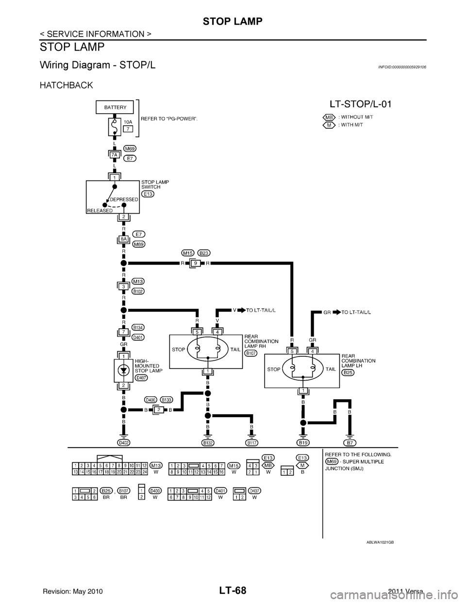
Wiring Diagram - STOP/LINFOID:0000000005929106
HATCHBACK
ABLWA1021GB
Revision: May 20102011 Versa
Page 3101 of 3787
STOP LAMPLT-69
< SERVICE INFORMATION >
C
DE
F
G H
I
J
L
M A
B
LT
N
O P
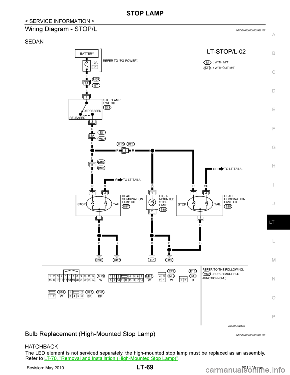
Wiring Diagram - STOP/LINFOID:0000000005929107
SEDAN
Bulb Replacement (High-Mounted Stop Lamp)INFOID:0000000005929108
HATCHBACK
The LED element is not serviced separately, the hi gh-mounted stop lamp must be replaced as an assembly.
Refer to LT-70, "
Removal and Installation (High-Mounted Stop Lamp)".
ABLWA1022GB
Revision: May 2010 2011 Versa
Page 3102 of 3787
LT-70
< SERVICE INFORMATION >
STOP LAMP
SEDAN - WITH REAR AIR SPOILER
The LED element is not serviced separately, the high-mounted stop lamp must be replaced as an assembly.
Refer to LT-70, "
Removal and Installation (High-Mounted Stop Lamp)".
1. Installation is in the reverse order of removal.
SEDAN - WITHOUT REAR AIR SPOILER
Removal
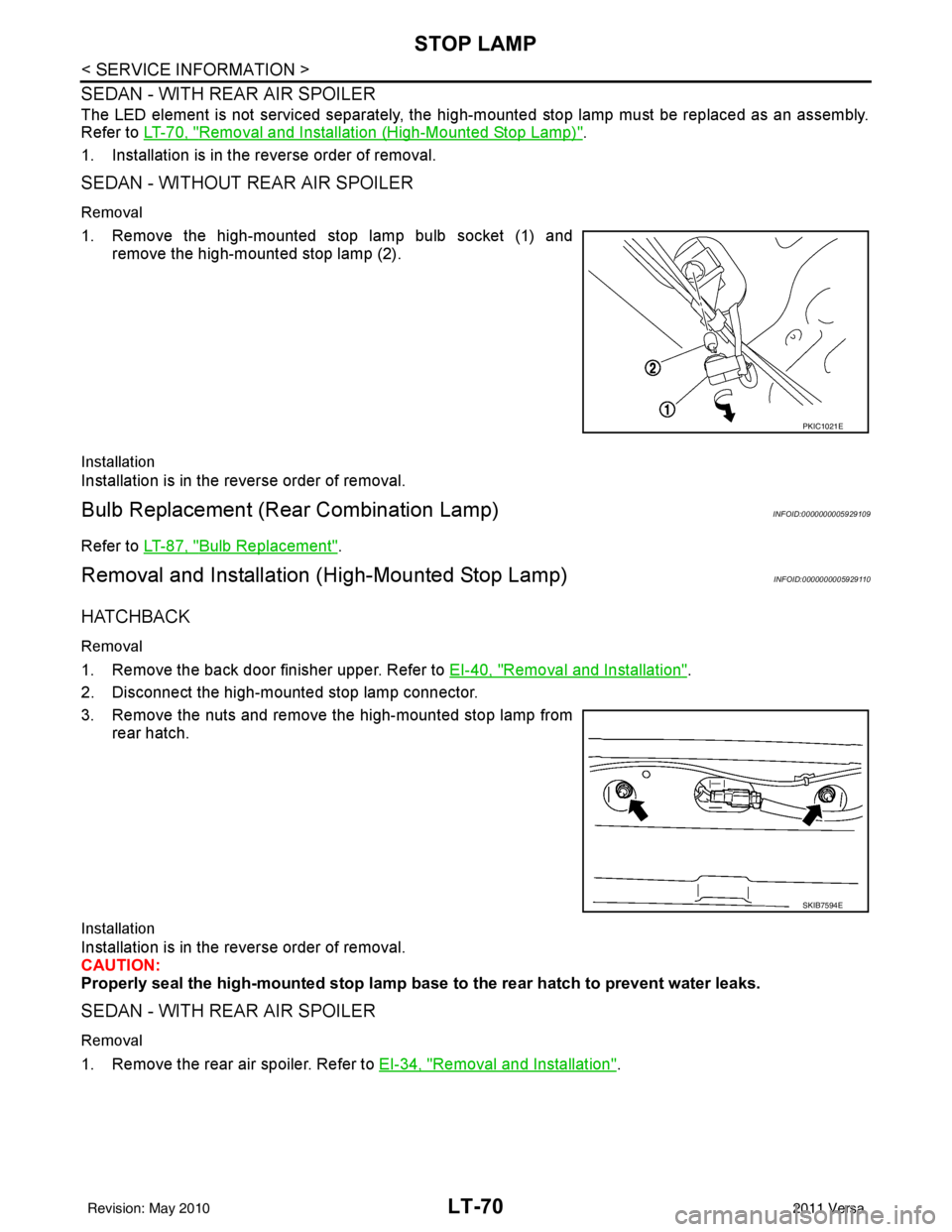
1. Remove the high-mounted stop lamp bulb socket (1) and remove the high-mounted stop lamp (2).
Installation
Installation is in the reverse order of removal.
Bulb Replacement (Rear Combination Lamp)INFOID:0000000005929109
Refer to LT-87, "Bulb Replacement".
Removal and Installation (High-Mounted Stop Lamp)INFOID:0000000005929110
HATCHBACK
Removal
1. Remove the back door finisher upper. Refer to EI-40, "Removal and Installation".
2. Disconnect the high-mounted stop lamp connector.
3. Remove the nuts and remove the high-mounted stop lamp from rear hatch.
Installation
Installation is in the reverse order of removal.
CAUTION:
Properly seal the high-mounted stop lamp b ase to the rear hatch to prevent water leaks.
SEDAN - WITH REAR AIR SPOILER
Removal
1. Remove the rear air spoiler. Refer to EI-34, "Removal and Installation".
PKIC1021E
SKIB7594E
Revision: May 2010 2011 Versa
Page 3107 of 3787
PARKING, LICENSE PLATE AND TAIL LAMPS
LT-75
< SERVICE INFORMATION >
C
D E
F
G H
I
J
L
M A
B
LT
N
O P
• to front combination lamp RH terminal 6,
• through IPDM E/R terminal 28
• to rear combination lamp LH terminal 4 and
• to license plate lamp LH and RH terminal 1,
• through IPDM E/R terminal 29
• to rear combination lamp RH terminal 4.
Ground is supplied
• to front combination lamp LH and RH terminal 7
• through grounds E15 and E24,
• to rear combination lamp LH terminal 1 and
• to license plate lamp LH and RH terminal 2
• through grounds B7 and B19, and
• to rear combination lamp RH terminal 1
• through grounds B117, B132 (all models) and D402 (with hatchback).
With power and ground supplied, parking, license plate and tail lamps illuminate.
COMBINATION SWITCH READING FUNCTION
Refer to BCS-4, "System Description" .
EXTERIOR LAMP BATTERY SAVER CONTROL
When the combination switch (lighting and turn signal switch) is in the 1ST (or 2ND) position and the ignition
switch is turned from ON or ACC to OFF, t he battery saver control feature is activated.
Under this condition, the parking, license and tail lamps remain illumi nated for 5 minutes, then the parking,
license plate and tail lamps are turned off.
Exterior lamp battery saver control mode can be changed by the function setting of CONSULT-III.
CAN Communication System DescriptionINFOID:0000000005929117
Refer to LAN-7, "System Description" .
Revision: May 2010 2011 Versa
Page 3111 of 3787
PARKING, LICENSE PLATE AND TAIL LAMPS
LT-79
< SERVICE INFORMATION >
C
D E
F
G H
I
J
L
M A
B
LT
N
O P
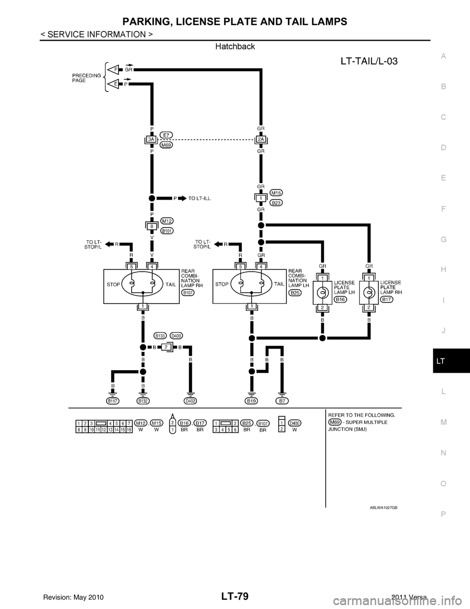
Hatchback
ABLWA1027GB
Revision: May 2010 2011 Versa