Page 2371 of 3787
BODY SIDE TRIMEI-41
< ON-VEHICLE REPAIR >
C
DE
F
G H
J
K L
M A
B
EI
N
O P
BODY SIDE TRIM
ComponentINFOID:0000000005929571
Hatchback Models
LIIA2574E
1. Front pillar garnish 2. Front body side welt 3. Front kicking plate inner
4. Front kicking plate outer 5. Center pillar lower garnish6. Rear kicking plate inner
7. Rear pillar finisher 8. Rear body side welt9. Rear kicking plate outer
10. Center pillar upper garnish PawlMetal clip
Clip Vehicle front
Revision: May 2010 2011 Versa
Page 2375 of 3787

BODY SIDE TRIMEI-45
< ON-VEHICLE REPAIR >
C
DE
F
G H
J
K L
M A
B
EI
N
O P
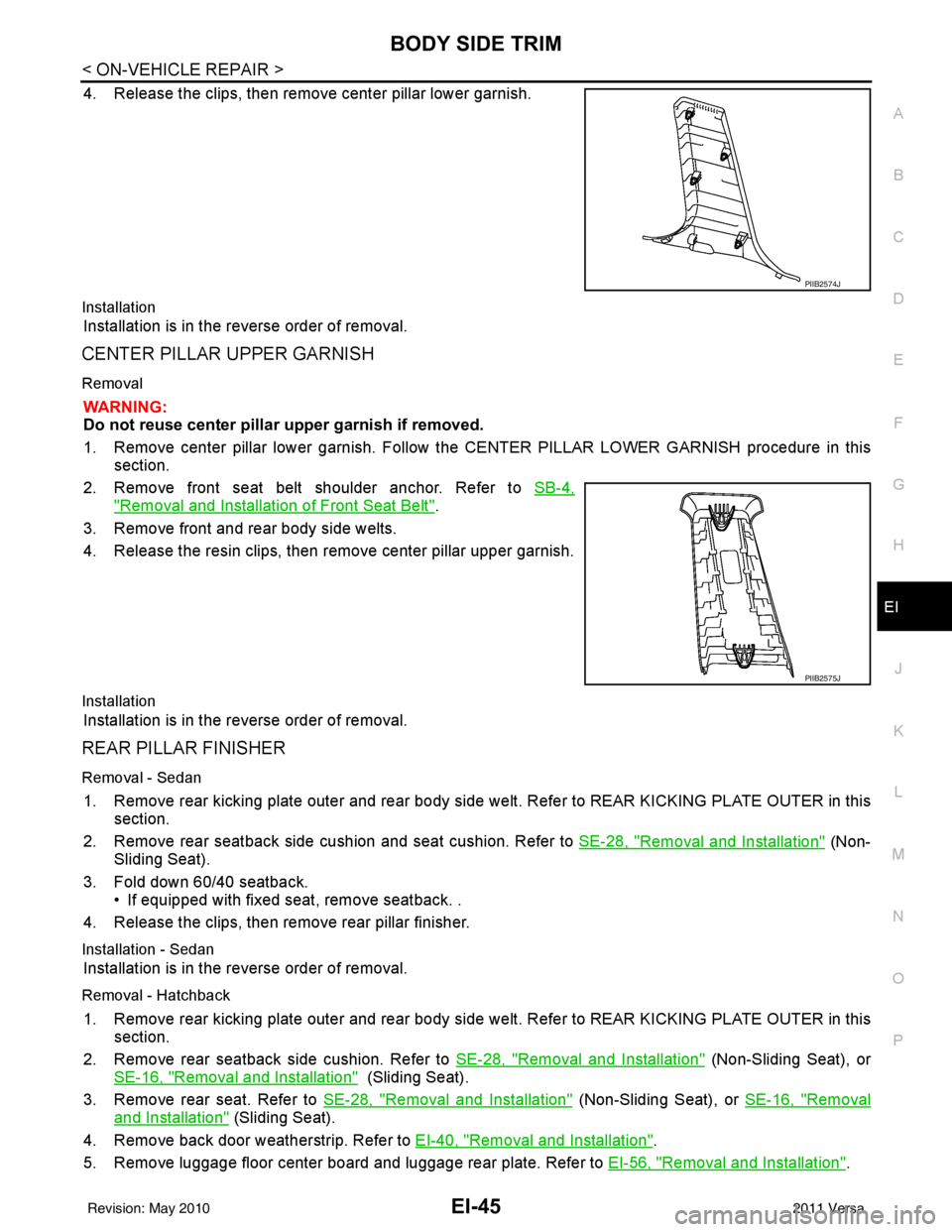
4. Release the clips, then remove center pillar lower garnish.
Installation
Installation is in the reverse order of removal.
CENTER PILLAR UPPER GARNISH
Removal
WARNING:
Do not reuse center pillar upper garnish if removed.
1. Remove center pillar lower garnish. Follow t he CENTER PILLAR LOWER GARNISH procedure in this
section.
2. Remove front seat belt shoulder anchor. Refer to SB-4,
"Removal and Installation of Front Seat Belt".
3. Remove front and rear body side welts.
4. Release the resin clips, then remove center pillar upper garnish.
Installation
Installation is in the reverse order of removal.
REAR PILLAR FINISHER
Removal - Sedan
1. Remove rear kicking plate outer and rear body side welt. Refer to REAR KICKING PLATE OUTER in this
section.
2. Remove rear seatback side cushion and seat cushion. Refer to SE-28, "
Removal and Installation" (Non-
Sliding Seat).
3. Fold down 60/40 seatback. • If equipped with fixed seat, remove seatback. .
4. Release the clips, then remove rear pillar finisher.
Installation - Sedan
Installation is in the reverse order of removal.
Removal - Hatchback
1. Remove rear kicking plate outer and rear body side welt. Refer to REAR KICKING PLATE OUTER in this
section.
2. Remove rear seatback side cushion. Refer to SE-28, "
Removal and Installation" (Non-Sliding Seat), or
SE-16, "
Removal and Installation" (Sliding Seat).
3. Remove rear seat. Refer to SE-28, "
Removal and Installation" (Non-Sliding Seat), or SE-16, "Removal
and Installation" (Sliding Seat).
4. Remove back door weatherstrip. Refer to EI-40, "
Removal and Installation".
5. Remove luggage floor center board and luggage rear plate. Refer to EI-56, "
Removal and Installation".
PIIB2574J
PIIB2575J
Revision: May 2010 2011 Versa
Page 2376 of 3787
EI-46
< ON-VEHICLE REPAIR >
BODY SIDE TRIM
6. Remove luggage side lower finisher. Refer to EI-56, "Removal and Installation".
7. Remove rear seat belt outer anchor bolt. Refer to SB-6, "
Removal and Installation of Rear Seat Belt".
8. Release the clips, then remove rear pillar finisher.
Installation - Hatchback
Installation is in the reverse order of removal.
Revision: May 2010 2011 Versa
Page 2378 of 3787
EI-48
< ON-VEHICLE REPAIR >
FLOOR TRIM
FLOOR TRIM
Removal and InstallationINFOID:0000000005929574
REMOVAL
1. Disconnect both the negative and positive battery terminals, then wait at least three minutes.
2. Remove front seat assembly RH/LH and rear seat cushion. Refer to SE-12, "
Removal and Installation"
(Front seat), and SE-16, "Removal and Installation" (60:40 Split Fold Down Seat - Hatchback), or SE-22,
"Removal and Installation" (60:40 Split Fold Down Seat - Sedan), or SE-28, "Removal and Installation"
(Fixed Back Seat).
3. Remove center console and floor bracket. Refer to IP-12, "
Removal and Installation".
4. Remove instrument lower cover. Refer to IP-12, "
Removal and Installation".
1. Clip C1012. Steering column shaft cover 3. Floor carpet hook
4. Front floor spacer 5. Rear floor spacer6. Floor trim
Metal clip Clip CF110Vehicle front
AWJIA0418ZZ
Revision: May 2010 2011 Versa
Page 2380 of 3787
EI-50
< ON-VEHICLE REPAIR >
HEADLINING
HEADLINING
ComponentINFOID:0000000005929575
Hatchback Models
LIIA2576E
1. Headlining2. Assist grip 3. Sunvisor
4. Cap 5. Sunvisor holder 6. Roof console retainer
Revision: May 2010 2011 Versa
Page 2382 of 3787

EI-52
< ON-VEHICLE REPAIR >
HEADLINING
Removal and Installation - Hatchback
INFOID:0000000005929576
REMOVAL
1. Disconnect the negative and positive battery termi nals, then wait at least three minutes.
2. Remove front seat assembly RH/LH. Refer to SE-12, "
Removal and Installation".
3. Remove rear seat cushion and rear seatback. Refer to SE-16, "
Removal and Installation" (60:40 Split Fold
Down Seat), or SE-28, "
Removal and Installation" (Fixed Back Seat).
4. Remove front seat belt shoulder anchor RH/LH. Refer to SB-4, "
Removal and Installation of Front Seat
Belt".
5. Remove center console body assembly. Refer to IP-11
.
6. Remove front pillar garnish RH/LH. Refer to EI-42, "
Removal and Installation".
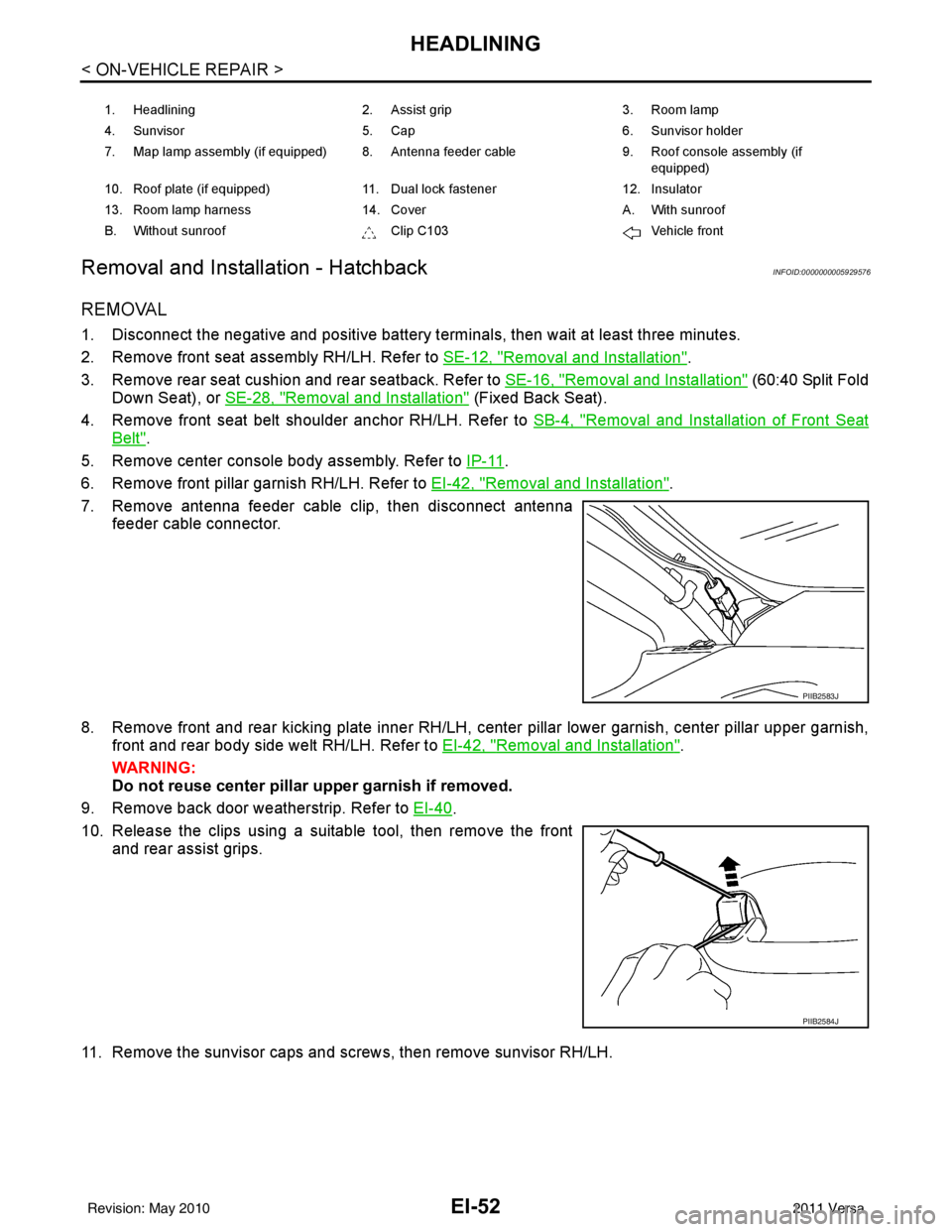
7. Remove antenna feeder cable clip, then disconnect antenna feeder cable connector.
8. Remove front and rear kicking plate inner RH/LH, center pillar lower garnish, center pillar upper garnish, front and rear body side welt RH/LH. Refer to EI-42, "
Removal and Installation".
WARNING:
Do not reuse center pillar upper garnish if removed.
9. Remove back door weatherstrip. Refer to EI-40
.
10. Release the clips using a suitable tool, then remove the front and rear assist grips.
11. Remove the sunvisor caps and screws, then remove sunvisor RH/LH.
1. Headlining 2. Assist grip 3. Room lamp
4. Sunvisor 5. Cap 6. Sunvisor holder
7. Map lamp assembly (if equipped) 8. Antenna feeder cable 9. Roof console assembly (if
equipped)
10. Roof plate (if equipped) 11. Dual lock fastener 12. Insulator
13. Room lamp harness 14. Cover A. With sunroof
B. Without sunroof Clip C103Vehicle front
PIIB2583J
PIIB2584J
Revision: May 2010 2011 Versa
Page 2673 of 3787

FL-6
< SERVICE INFORMATION >
FUEL LEVEL SENSOR UNIT, FUEL FILTER AND FUEL PUMP ASSEMBLY
FUEL LEVEL SENSOR UNIT, FUEL FILTER AND FUEL PUMP ASSEMBLY
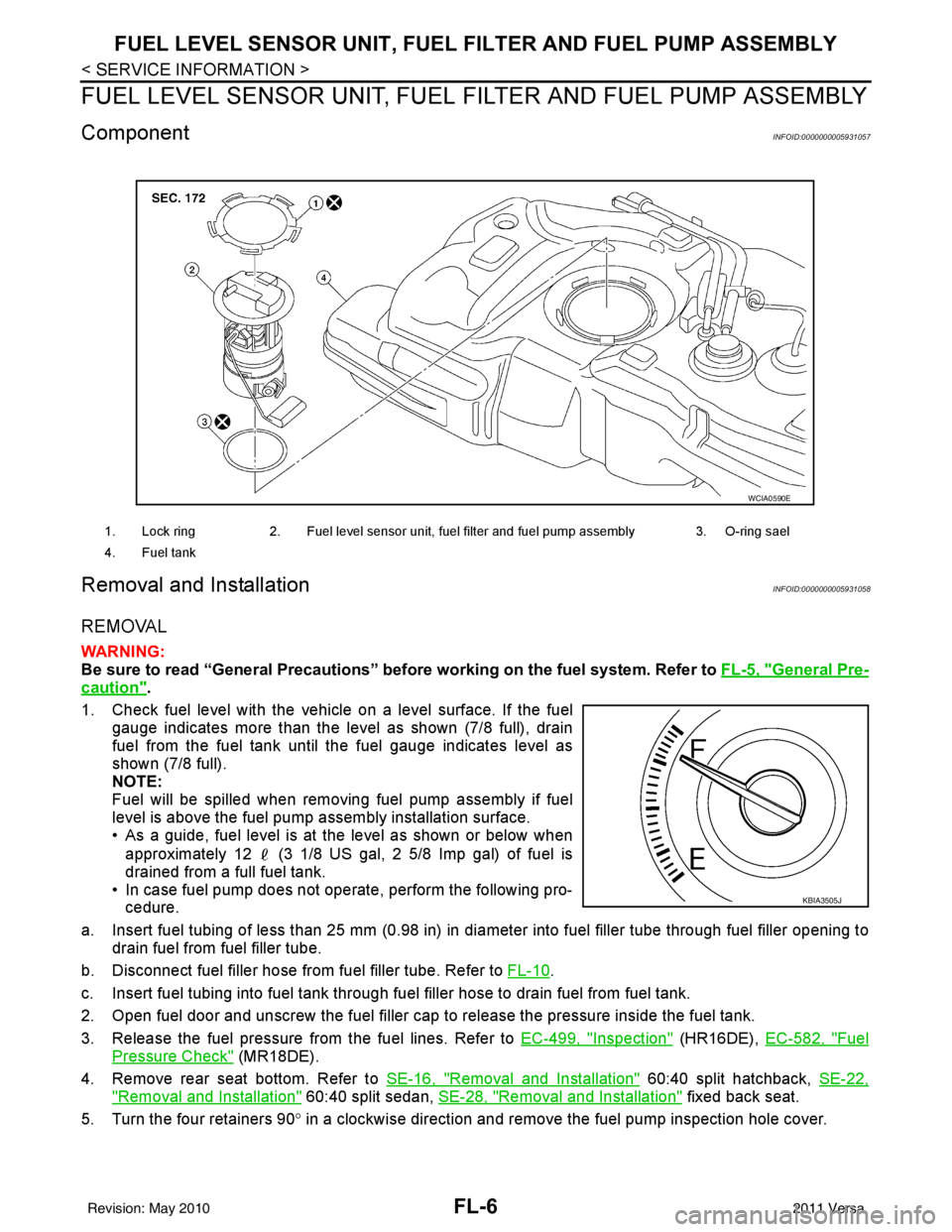
ComponentINFOID:0000000005931057
Removal and InstallationINFOID:0000000005931058
REMOVAL
WARNING:
Be sure to read “General Precautions” be fore working on the fuel system. Refer to FL-5, "
General Pre-
caution".
1. Check fuel level with the vehicle on a level surface. If the fuel gauge indicates more than the level as shown (7/8 full), drain
fuel from the fuel tank until the fuel gauge indicates level as
shown (7/8 full).
NOTE:
Fuel will be spilled when removing fuel pump assembly if fuel
level is above the fuel pump assembly installation surface.
• As a guide, fuel level is at the level as shown or below when
approximately 12 (3 1/8 US gal, 2 5/8 Imp gal) of fuel is
drained from a full fuel tank.
• In case fuel pump does not operate, perform the following pro- cedure.
a. Insert fuel tubing of less than 25 mm (0.98 in) in di ameter into fuel filler tube through fuel filler opening to
drain fuel from fuel filler tube.
b. Disconnect fuel filler hose from fuel filler tube. Refer to FL-10
.
c. Insert fuel tubing into fuel tank through f uel filler hose to drain fuel from fuel tank.
2. Open fuel door and unscrew the fuel filler cap to release the pressure inside the fuel tank.
3. Release the fuel pressure from the fuel lines. Refer to EC-499, "
Inspection" (HR16DE), EC-582, "Fuel
Pressure Check" (MR18DE).
4. Remove rear seat bottom. Refer to SE-16, "
Removal and Installation" 60:40 split hatchback, SE-22,
"Removal and Installation" 60:40 split sedan, SE-28, "Removal and Installation" fixed back seat.
5. Turn the four retainers 90 ° in a clockwise direction and remove the fuel pump inspection hole cover.
1. Lock ring 2. Fuel level sensor unit, fuel filter and fuel pump assembly 3. O-ring sael
4. Fuel tank
WCIA0590E
KBIA3505J
Revision: May 2010 2011 Versa
Page 2677 of 3787

FL-10
< SERVICE INFORMATION >
FUEL TANK
FUEL TANK
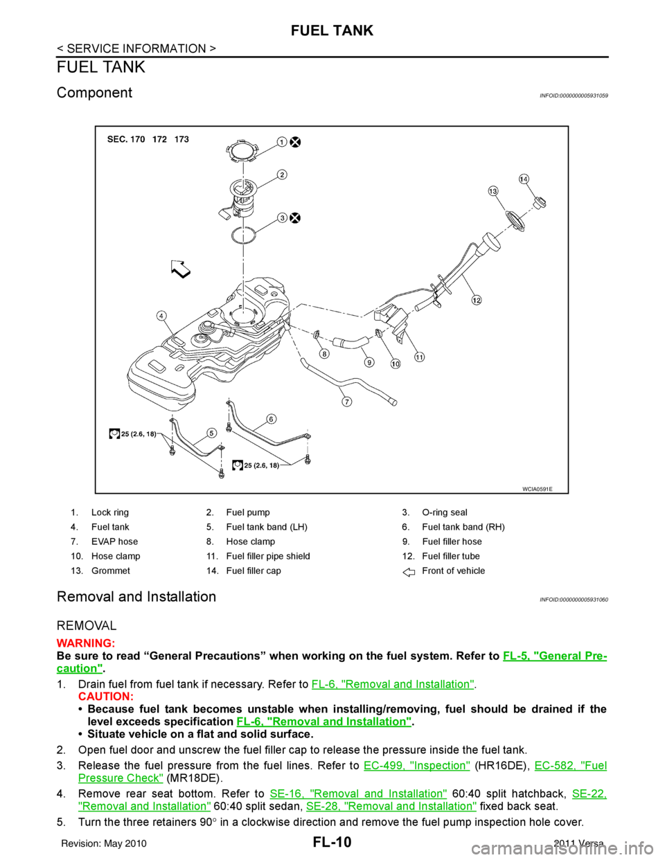
ComponentINFOID:0000000005931059
Removal and InstallationINFOID:0000000005931060
REMOVAL
WARNING:
Be sure to read “General Precautions” when working on the fuel system. Refer to FL-5, "
General Pre-
caution".
1. Drain fuel from fuel tank if necessary. Refer to FL-6, "
Removal and Installation".
CAUTION:
• Because fuel tank becomes unstable when installing/removing, fuel should be drained if the
level exceeds specification FL-6, "
Removal and Installation".
• Situate vehicle on a flat and solid surface.
2. Open fuel door and unscrew the fuel filler cap to release the pressure inside the fuel tank.
3. Release the fuel pressure from the fuel lines. Refer to EC-499, "
Inspection" (HR16DE), EC-582, "Fuel
Pressure Check" (MR18DE).
4. Remove rear seat bottom. Refer to SE-16, "
Removal and Installation" 60:40 split hatchback, SE-22,
"Removal and Installation" 60:40 split sedan, SE-28, "Removal and Installation" fixed back seat.
5. Turn the three retainers 90 ° in a clockwise direction and remove the fuel pump inspection hole cover.
1. Lock ring 2. Fuel pump 3. O-ring seal
4. Fuel tank 5. Fuel tank band (LH) 6. Fuel tank band (RH)
7. EVAP hose 8. Hose clamp 9. Fuel filler hose
10. Hose clamp 11. Fuel filler pipe shield 12. Fuel filler tube
13. Grommet 14. Fuel filler cap Front of vehicle
WCIA0591E
Revision: May 2010 2011 Versa