Page 25 of 3787

AT-8
< SERVICE INFORMATION >
PRECAUTIONS
6. Perform a self-diagnosis check of all control units using CONSULT-III.
Precaution for On Board Diagnosis (OBD) System of A/T and EngineINFOID:0000000005928065
The ECM has an on board diagnostic system. It will light up the malfunction indicator lamp (MIL) to warn the
driver of a malfunction causing emission deterioration.
CAUTION:
• Be sure to turn the ignition switch OFF and disconnect battery negative cable from battery negative
terminal before any repair or inspection work. The open/short circuit of related switches, sensors,
solenoid valves, etc. will cause the MIL to light up.
• Be sure to connect and lock the connectors secure ly after work. A loose (unlocked) connector will
cause the MIL to light up due to an open circuit. (Be sure the connectors are free from water, grease,
dirt, bent terminals, etc.)
• Be sure to route and secure th e harnesses properly after work. Interference of the harness with a
bracket, etc. may cause the MIL to light up due to a short circuit.
• Be sure to erase the unnecessary malfunction informa tion (repairs completed) from the TCM and
ECM before returning the vehicle to the customer.
PrecautionINFOID:0000000005928066
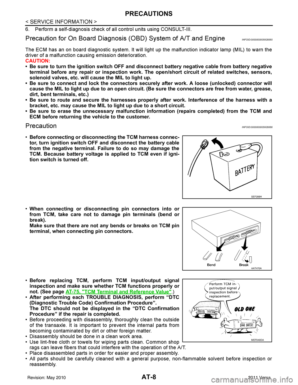
•Before connecting or disconn ecting the TCM harness connec-
tor, turn ignition switch OF F and disconnect the battery cable
from the negative terminal. Failure to do so may damage the
TCM. Because battery voltage is applied to TCM even if igni-
tion switch is turned off.
• When connecting or disconnect ing pin connectors into or
from TCM, take care not to damage pin terminals (bend or
break).
Make sure that there are not any bends or breaks on TCM pin
terminal, when connecting pin connectors.
• Before replacing TCM, perform TCM input/output signal
inspection and make sure whether TCM functions properly or
not. (See page AT-75, "
TCM Terminal and Reference Value".)
• After performing each TROUBLE DIAGNOSIS, perform “DTC
(Diagnostic Trouble Code) Confirmation Procedure”.
The DTC should not be displ ayed in the “DTC Confirmation
Procedure” if the repair is completed.
• Before proceeding with disassembly, thoroughly clean the outside of the transaxle. It is important to prevent the internal parts from
becoming contaminated by dirt or other foreign matter.
• Disassembly should be done in a clean work area.
• Use lint-free cloth or towels for wiping parts clean. Common shop rags can leave fibers that could in terfere with the operation of the A/T.
• Place disassembled parts in order for easier and proper assembly.
• All parts should be carefully cleaned with a general purpose, non-flammable solvent before inspection or reassembly.
SEF289H
AAT470A
MEF040DA
Revision: May 2010 2011 Versa
Page 36 of 3787

A/T FLUIDAT-19
< SERVICE INFORMATION >
DE
F
G H
I
J
K L
M A
B
AT
N
O P
13. Flush each steel line from the cooler side back toward the A/T by spraying Transmission Cooler Cleaner in a continuous stream for 5 seconds.
14. Blow compressed air regulated to 5 - 9 kg/cm
2 (490 - 883 kPa, 71 - 128 psi) through each steel line from
the cooler side back toward the A/T for 10 seconds to force out any remaining A/T fluid.
15. Ensure all debris is removed from the steel cooler lines.
16. Ensure all debris is removed from the banjo bolts and fittings.
17. Perform "A/T FLUID COOL ER DIAGNOSIS PROCEDURE".
A/T FLUID COOLER DIAGNOSIS PROCEDURE
NOTE:
Insufficient cleaning of the cooler inlet hose exte rior may lead to inaccurate debris identification.
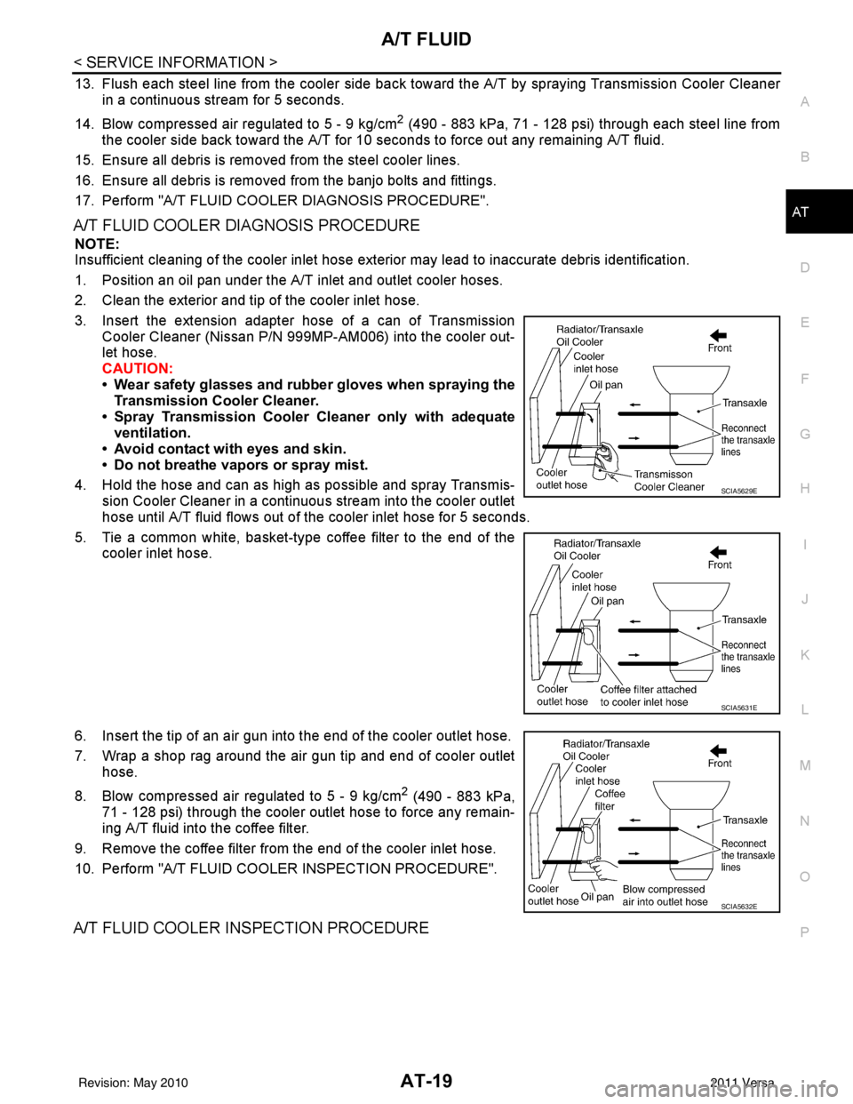
1. Position an oil pan under the A/T inlet and outlet cooler hoses.
2. Clean the exterior and tip of the cooler inlet hose.
3. Insert the extension adapter hose of a can of Transmission Cooler Cleaner (Nissan P/N 999MP-AM006) into the cooler out-
let hose.
CAUTION:
• Wear safety glasses and rubber gloves when spraying the
Transmission Cooler Cleaner.
• Spray Transmission Cooler Cleaner only with adequate
ventilation.
• Avoid contact with eyes and skin.
• Do not breathe vapors or spray mist.
4. Hold the hose and can as high as possible and spray Transmis- sion Cooler Cleaner in a continuous stream into the cooler outlet
hose until A/T fluid flows out of t he cooler inlet hose for 5 seconds.
5. Tie a common white, basket-type coffee filter to the end of the cooler inlet hose.
6. Insert the tip of an air gun into the end of the cooler outlet hose.
7. Wrap a shop rag around the air gun tip and end of cooler outlet hose.
8. Blow compressed air regulated to 5 - 9 kg/cm
2 (490 - 883 kPa,
71 - 128 psi) through the cooler outlet hose to force any remain-
ing A/T fluid into the coffee filter.
9. Remove the coffee filter from the end of the cooler inlet hose.
10. Perform "A/T FLUID COOL ER INSPECTION PROCEDURE".
A/T FLUID COOLER INSPECTION PROCEDURE
SCIA5629E
SCIA5631E
SCIA5632E
Revision: May 2010 2011 Versa
Page 232 of 3787
SHIFT CONTROL SYSTEMAT-215
< SERVICE INFORMATION >
DE
F
G H
I
J
K L
M A
B
AT
N
O P
7. Remove the plate (1) from the A/T shift selector assembly. : Vehicle front
8. Remove the lock plate (1) from the shift selector control cable (2).
: Vehicle front
9. Remove the shift selector control cable (2) from the A/T shift selector assembly.
10. Insert suitable tool at points (A) and (B) as shown, and press both tabs (E) and (F) at the front (C) and rear (D) slightly toward
the center of the A/T shift select or assembly to remove the A/T
shift selector assembly from the underside of the vehicle.
: Vehicle front
INSTALLATION
Installation is in the reverse order of removal.
SCIA6967E
SCIA6968E
SCIA6970E
Revision: May 2010 2011 Versa
Page 235 of 3787
AT-218
< SERVICE INFORMATION >
SHIFT CONTROL SYSTEM
5. The method of operating shift selector to individual positions cor-rectly should be as shown.
• (A): Press shift selector handle button to operate shift selector,while depressing the brake pedal.
• (B): Press shift selector handle button to operate shift selector.
• (C): Shift selector can be operated without pressing shift selector handle button.
6. Confirm back-up lamps illuminate only when shift selector is placed in “R” position. Confirm back-up lamps do not illuminate
when shift selector is in “P” or “N” position even if it is pushed
toward “R” position without pressing shift selector handle button.
7. Confirm engine can only be started with shift selector in “P” and “N” positions.
8. Make sure A/T is locked completely in “P” position.
WCIA0636E
Revision: May 2010 2011 Versa
Page 236 of 3787
KEY INTERLOCK CABLEAT-219
< SERVICE INFORMATION >
DE
F
G H
I
J
K L
M A
B
AT
N
O P
KEY INTERLOCK CABLE
Removal and InstallationINFOID:0000000005928277
COMPONENTS
REMOVAL
CAUTION:
Make sure that parking brake is applie d before removal and installation.
1. Place the shift selector in the “N” position.
2. Remove the shift selector handle. Refer to AT-216, "
Shift Selector Handle Removal and Installation".
3. Remove the center console assembly. Refer to IP-11
.
4. Slide the slider (A) toward the casing cap (B) while pressing tabs (C) on the slider to separate the slider (A) from the adjust holder
(D).
5. Remove the casing cap (B) from the cable bracket on the A/T shift selector assembly.
6. Remove the key interlock cable from the key interlock rod (E).
1. Key interlock cable 2. Key cylinder3. A/T shift selector assembly
A. Lock plate B. HolderC. Clip
D. Slider E. Key interlock rodF. Adjust holder
G. C a s i n g c a p
WCIA0621E
SCIA6975E
Revision: May 2010 2011 Versa
Page 238 of 3787
KEY INTERLOCK CABLEAT-221
< SERVICE INFORMATION >
DE
F
G H
I
J
K L
M A
B
AT
N
O P
8. Slide the slider (A) toward the key interlock rod (D) while press- ing the pull lock (B) down to securely connect the adjust holder
(C) with the key interlock rod (D).
CAUTION:
• Do not press tabs when holding slider (A).
• Do not apply any side to side force to key interlock rod (D)when sliding slider (A).
9. Secure the key interlock cable (1) with the clip (A).
10. Install steering column cover (upper and lower) and instrument lower finisher. Refer to IP-11
.
11. Install the center console assembly. Refer to IP-11
.
12. Install the shift selector handle. Refer to AT-216, "
Shift Selector
Handle Removal and Installation".
13. Check shift lock system. Refer to AT-206, "
Description".
SCIA6978E
SCIA6973E
Revision: May 2010 2011 Versa
Page 677 of 3787

FRONT DOOR LOCKBL-167
< SERVICE INFORMATION >
C
DE
F
G H
J
K L
M A
B
BL
N
O P
FRONT DOOR LOCK
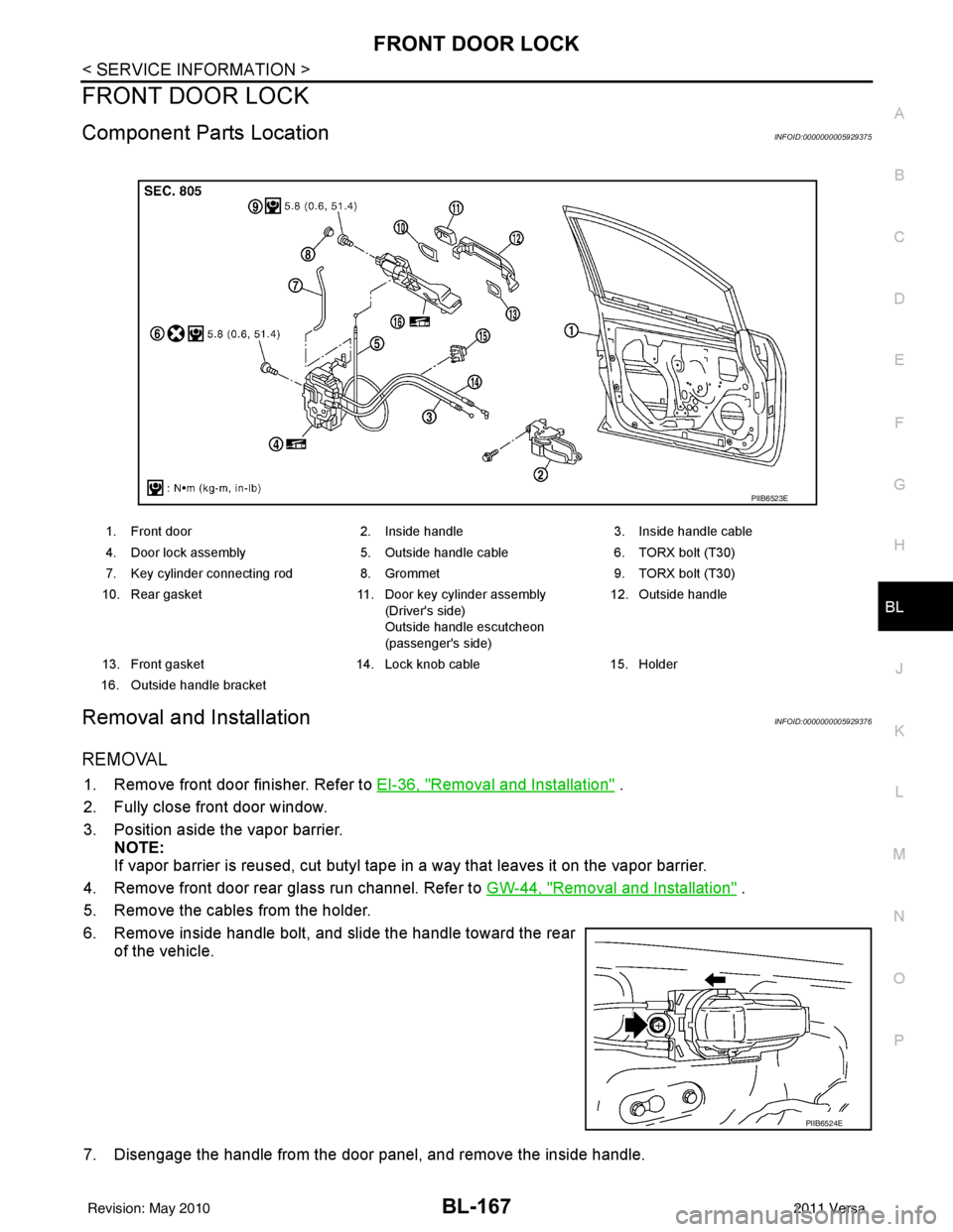
Component Parts LocationINFOID:0000000005929375
Removal and InstallationINFOID:0000000005929376
REMOVAL
1. Remove front door finisher. Refer to EI-36, "Removal and Installation" .
2. Fully close front door window.
3. Position aside the vapor barrier. NOTE:
If vapor barrier is reused, cut butyl tape in a way that leaves it on the vapor barrier.
4. Remove front door rear glass run channel. Refer to GW-44, "
Removal and Installation" .
5. Remove the cables from the holder.
6. Remove inside handle bolt, and slide the handle toward the rear of the vehicle.
7. Disengage the handle from the door panel, and remove the inside handle.
1. Front door 2. Inside handle3. Inside handle cable
4. Door lock assembly 5. Outside handle cable6. TORX bolt (T30)
7. Key cylinder connecting rod 8. Grommet9. TORX bolt (T30)
10. Rear gasket 11. Door key cylinder assembly
(Driver's side)
Outside handle escutcheon
(passenger's side) 12. Outside handle
13. Front gasket 14. Lock knob cable15. Holder
16. Outside handle bracket
PIIB6523E
PIIB6524E
Revision: May 2010 2011 Versa
Page 678 of 3787
BL-168
< SERVICE INFORMATION >
FRONT DOOR LOCK
8. Disconnect the inside handle cable and lock knob cable from theinside handle.
CAUTION:
During removal and installation , work so as not to bend the
ends of the lock knob cable and inside handle cable.
9. Remove the door side grommet, and the door key cylinder assembly (escutcheon) bolt.
10. Remove the key cylinder connecting rod (key cylinder side).
11. If equipped, disconnect the door antenna, the door request switch connector and remove the harness clamp. (Vehicle with
intelligent key systems only).
12. Remove the door cylinder assembly while pulling the outside handle forward.
13. Pull the outside door handle forward and then slide it toward the rear of the vehicle to remove.
14. Remove the front and rear gaskets.
PIIB6525E
PIIB5808E
PIIB5809E
PIIB5810E
PIIB6526E
Revision: May 2010 2011 Versa