2011 NISSAN LATIO trunk release
[x] Cancel search: trunk releasePage 497 of 3787

BCM (BODY CONTROL MODULE)BCS-7
< SERVICE INFORMATION >
C
DE
F
G H
I
J
L
M A
B
BCS
N
O P
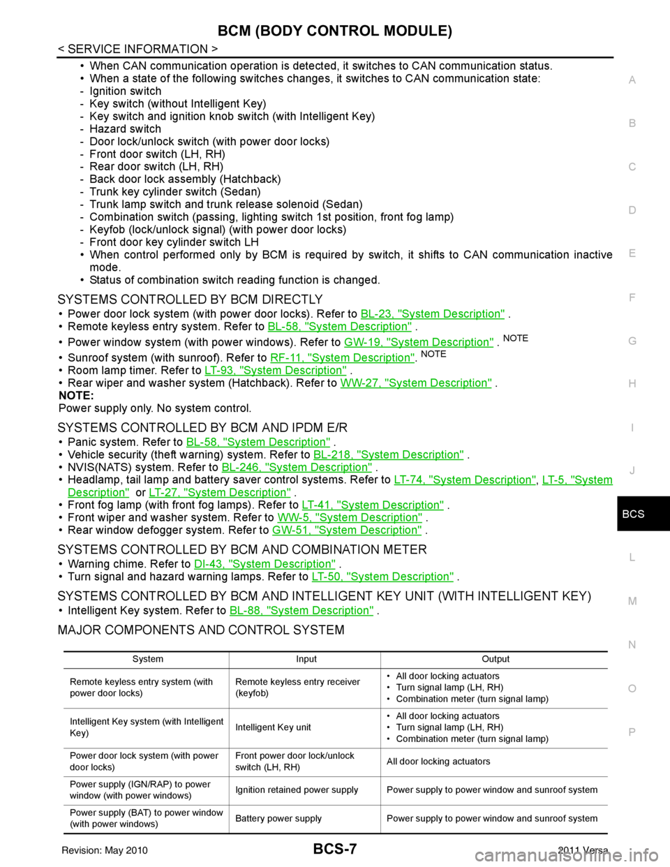
• When CAN communication operation is detected, it switches to CAN communication status.
• When a state of the following switches changes , it switches to CAN communication state:
- Ignition switch
- Key switch (without Intelligent Key)
- Key switch and ignition knob switch (with Intelligent Key)
- Hazard switch
- Door lock/unlock switch (with power door locks)
- Front door switch (LH, RH)
- Rear door switch (LH, RH)
- Back door lock assembly (Hatchback)
- Trunk key cylinder switch (Sedan)
- Trunk lamp switch and trunk release solenoid (Sedan)
- Combination switch (passing, lighting switch 1st position, front fog lamp)
- Keyfob (lock/unlock signal) (with power door locks)
- Front door key cylinder switch LH
• When control performed only by BCM is required by switch, it shifts to CAN communication inactive mode.
• Status of combination switch reading function is changed.
SYSTEMS CONTROLLED BY BCM DIRECTLY
• Power door lock system (with power door locks). Refer to BL-23, "System Description" .
• Remote keyless entry system. Refer to BL-58, "
System Description" .
• Power window system (with power windows). Refer to GW-19, "
System Description" . NOTE
• Sunroof system (with sunroof). Refer to RF-11, "System Description". NOTE
• Room lamp timer. Refer to LT-93, "System Description" .
• Rear wiper and washer system (Hatchback). Refer to WW-27, "
System Description" .
NOTE:
Power supply only. No system control.
SYSTEMS CONTROLLED BY BCM AND IPDM E/R
• Panic system. Refer to BL-58, "System Description" .
• Vehicle security (theft warning) system. Refer to BL-218, "
System Description" .
• NVIS(NATS) system. Refer to BL-246, "
System Description" .
• Headlamp, tail lamp and battery saver control systems. Refer to LT-74, "
System Description", LT- 5 , "System
Description" or LT-27, "System Description" .
• Front fog lamp (with front fog lamps). Refer to LT-41, "
System Description" .
• Front wiper and washer system. Refer to WW-5, "
System Description" .
• Rear window defogger system. Refer to GW-51, "
System Description" .
SYSTEMS CONTROLLED BY BCM AND COMBINATION METER
• Warning chime. Refer to DI-43, "System Description" .
• Turn signal and hazard warning lamps. Refer to LT-50, "
System Description" .
SYSTEMS CONTROLLED BY BCM AND INTELLIGENT KEY UNIT (WITH INTELLIGENT KEY)
• Intelligent Key system. Refer to BL-88, "System Description" .
MAJOR COMPONENTS AND CONTROL SYSTEM
System Input Output
Remote keyless entry system (with
power door locks) Remote keyless entry receiver
(keyfob)• All door locking actuators
• Turn signal lamp (LH, RH)
• Combination meter (turn signal lamp)
Intelligent Key system (with Intelligent
Key) Intelligent Key unit• All door locking actuators
• Turn signal lamp (LH, RH)
• Combination meter (turn signal lamp)
Power door lock system (with power
door locks) Front power door lock/unlock
switch (LH, RH)
All door locking actuators
Power supply (IGN /RAP) to power
window (with power windows) Ignition retained power supply Power supply to power window and sunroof system
Power supply (BAT) to power window
(with power windows) Battery power supply
Power supply to power window and sunroof system
Revision: May 2010 2011 Versa
Page 505 of 3787

BCM (BODY CONTROL MODULE)BCS-15
< SERVICE INFORMATION >
C
DE
F
G H
I
J
L
M A
B
BCS
N
O P
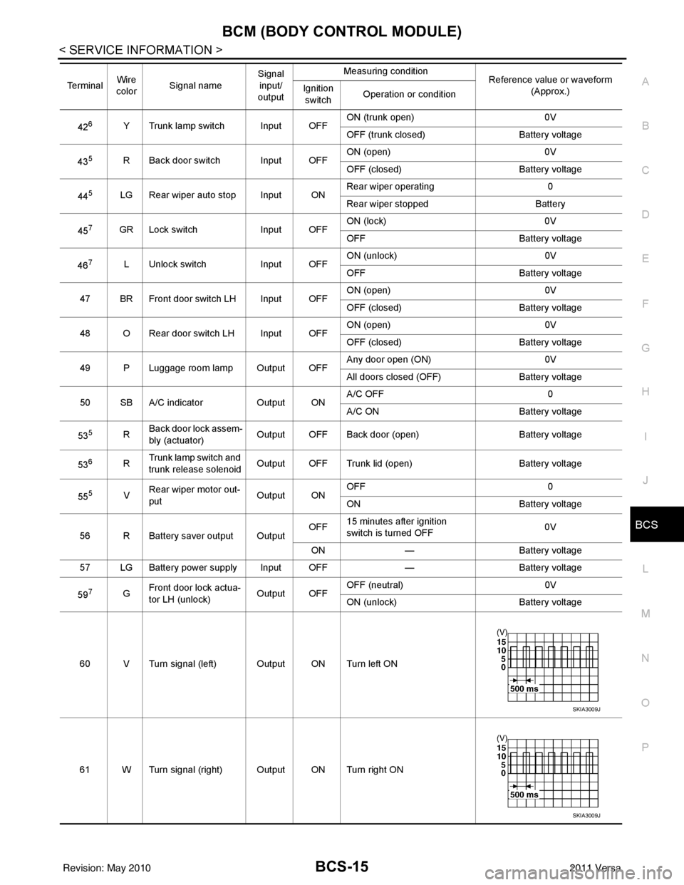
426Y Trunk lamp switch Input OFF ON (trunk open)
0V
OFF (trunk closed) Battery voltage
43
5R Back door switch Input OFF ON (open) 0V
OFF (closed)
Battery voltage
44
5LG Rear wiper auto stop Input ON Rear wiper operating 0
Rear wiper stopped
Battery
45
7GR Lock switch Input OFFON (lock)
0V
OFF Battery voltage
46
7L Unlock switch Input OFFON (unlock)
0V
OFF Battery voltage
47 BR Front door switch LH Input OFF ON (open)
0V
OFF (closed) Battery voltage
48 O Rear door switch LH Input OFF ON (open)
0V
OFF (closed) Battery voltage
49 P Luggage room lamp Output OFF Any door open (ON)
0V
All doors closed (OFF) Battery voltage
50 SB A/C indicator Output ONA/C OFF
0
A/C ON Battery voltage
53
5R Back door lock assem-
bly (actuator)
Output OFF Back door (open)
Battery voltage
53
6R Trunk lamp switch and
trunk release solenoid Output OFF Trunk lid (open)
Battery voltage
55
5V Rear wiper motor out-
put
Output ONOFF
0
ON Battery voltage
56 R Battery saver output Output OFF
15 minutes after ignition
switch is turned OFF 0V
ON — Battery voltage
57 LG Battery power supply Input OFF —Battery voltage
59
7G Front door lock actua-
tor LH (unlock)
Output OFFOFF (neutral)
0V
ON (unlock) Battery voltage
60 V Turn signal (left) Output ON Turn left ON
61 W Turn signal (right) Output ON Turn right ON
Te r m i n a l
Wire
color Signal name Signal
input/
output Measuring condition
Reference value or waveform
(Approx.)
Ignition
switch Operation or condition
SKIA3009J
SKIA3009J
Revision: May 2010
2011 Versa
Page 513 of 3787

BL-3
C
DE
F
G H
J
K L
M A
B
BL
N
O P
Check Trunk Lid Opener S
witch Circuit (Without
Intelligent Key) .................................................... ..
209
Check Trunk Lid Opener Switch Circuit (With Intel-
ligent Key) ........................................................... ..
212
Check Trunk Release Solenoid Circuit .................214
FUEL FILLER LID OPENER ............................216
Removal and Installation of Fuel Filler Lid Opener ..216
VEHICLE SECURITY (THEFT WARNING)
SYSTEM ...........................................................
217
Component Parts and Harness Connector Loca-
tion ...................................................................... ..
217
System Description ...............................................218
CAN Communication System Description .............220
Schematic .............................................................221
Wiring Diagram - VEHSEC - .................................222
Terminal and Reference Value for BCM ...............226
Terminal and Reference Value for Intelligent Key
Unit ...................................................................... ..
230
CONSULT-III Function (BCM) ...............................232
Trouble Diagnosis .................................................234
Preliminary Check .................................................234
Symptom Chart .....................................................236
Diagnosis Procedure 1 ..........................................237
Diagnosis Procedure 2 ..........................................239
Diagnosis Procedure 3 ..........................................240
Diagnosis Procedure 4 ..........................................240
Diagnosis Procedure 5 ..........................................240
Diagnosis Procedure 6 ..........................................241
Diagnosis Procedure 7 ..........................................241
Diagnosis Procedure 8 ..........................................242
Diagnosis Procedure 9 ........................................ ..244
NATS (Nissan Anti-Theft System) ................246
Component Parts and Harness Connector Loca-
tion .........................................................................
246
System Description ................................................246
System Composition ..............................................247
ECM Re-communicating Function .........................247
Wiring Diagram - NATS - .......................................249
Terminal and Reference Value for BCM ................250
CONSULT-III Function ........................................ ..254
Trouble Diagnosis Procedure ................................255
Trouble Diagnosis ..................................................257
Diagnosis Procedure 1 ..........................................258
Diagnosis Procedure 2 ..........................................260
Diagnosis Procedure 3 ..........................................261
Diagnosis Procedure 4 ..........................................262
Diagnosis Procedure 5 ..........................................263
Diagnosis Procedure 6 ..........................................264
How to Replace NATS Antenna Amp ....................264
BODY REPAIR ................................................265
Body Exterior Paint Color ......................................265
Body Component Parts .........................................267
Corrosion Protection ..............................................272
Body Sealing .........................................................276
Body Construction .................................................282
Body Alignment .....................................................284
Handling Precaution for Plastics ............................301
Precaution in Repairing High Strength Steel .........305
Foam Repair ..........................................................308
Replacement Operation .........................................311
Revision: May 2010 2011 Versa
Page 550 of 3787

BL-40
< SERVICE INFORMATION >
POWER DOOR LOCK SYSTEM
426Y Trunk lamp switch Input OFFON (trunk open)
0V
OFF (trunk closed) Battery voltage
43
5R Back door switch Input OFF ON (open) 0V
OFF (closed)
Battery voltage
44
5LG Rear wiper auto stop Input ON Rear wiper operating 0
Rear wiper stopped
Battery
45
7GR Lock switch Input OFFON (lock)
0V
OFF Battery voltage
46
7L Unlock switch Input OFFON (unlock)
0V
OFF Battery voltage
47 BR Front door switch LH Input OFF ON (open)
0V
OFF (closed) Battery voltage
48 O Rear door switch LH Input OFF ON (open)
0V
OFF (closed) Battery voltage
49 P Luggage room lamp Output OFF Any door open (ON)
0V
All doors closed (OFF) Battery voltage
50 SB A/C indicator Output ONA/C OFF
0
A/C ON Battery voltage
53
5R Back door lock assem-
bly (actuator)
Output OFF Back door (open)
Battery voltage
53
6R Trunk lamp switch and
trunk release solenoid Output OFF Trunk lid (open)
Battery voltage
55
5V Rear wiper motor out-
put
Output ONOFF
0
ON Battery voltage
56 R Battery saver output Output OFF
15 minutes after ignition
switch is turned OFF 0V
ON — Battery voltage
57 LG Battery power supply Input OFF —Battery voltage
59
7G Front door lock actua-
tor LH (unlock)
Output OFFOFF (neutral)
0V
ON (unlock) Battery voltage
60 V Turn signal (left) Output ON Turn left ON
61 W Turn signal (right) Output ON Turn right ON
Te r m i n a l
Wire
color Signal name Signal
input/
output Measuring condition
Reference value or waveform
(Approx.)
Ignition
switch Operation or condition
SKIA3009J
SKIA3009J
Revision: May 2010
2011 Versa
Page 578 of 3787

BL-68
< SERVICE INFORMATION >
REMOTE KEYLESS ENTRY SYSTEM
426Y Trunk lamp switch Input OFFON (trunk open)
0V
OFF (trunk closed) Battery voltage
43
5R Back door switch Input OFF ON (open) 0V
OFF (closed)
Battery voltage
44
5LG Rear wiper auto stop Input ON Rear wiper operating 0
Rear wiper stopped
Battery
45
7GR Lock switch Input OFFON (lock)
0V
OFF Battery voltage
46
7L Unlock switch Input OFFON (unlock)
0V
OFF Battery voltage
47 BR Front door switch LH Input OFF ON (open)
0V
OFF (closed) Battery voltage
48 O Rear door switch LH Input OFF ON (open)
0V
OFF (closed) Battery voltage
49 P Luggage room lamp Output OFF Any door open (ON)
0V
All doors closed (OFF) Battery voltage
50 SB A/C indicator Output ONA/C OFF
0
A/C ON Battery voltage
53
5R Back door lock assem-
bly (actuator)
Output OFF Back door (open)
Battery voltage
53
6R Trunk lamp switch and
trunk release solenoid Output OFF Trunk lid (open)
Battery voltage
55
5V Rear wiper motor out-
put
Output ONOFF
0
ON Battery voltage
56 R Battery saver output Output OFF
15 minutes after ignition
switch is turned OFF 0V
ON — Battery voltage
57 LG Battery power supply Input OFF —Battery voltage
59
7G Front door lock actua-
tor LH (unlock)
Output OFFOFF (neutral)
0V
ON (unlock) Battery voltage
60 V Turn signal (left) Output ON Turn left ON
61 W Turn signal (right) Output ON Turn right ON
Te r m i n a l
Wire
color Signal name Signal
input/
output Measuring condition
Reference value or waveform
(Approx.)
Ignition
switch Operation or condition
SKIA3009J
SKIA3009J
Revision: May 2010
2011 Versa
Page 581 of 3787

REMOTE KEYLESS ENTRY SYSTEMBL-71
< SERVICE INFORMATION >
C
DE
F
G H
J
K L
M A
B
BL
N
O P
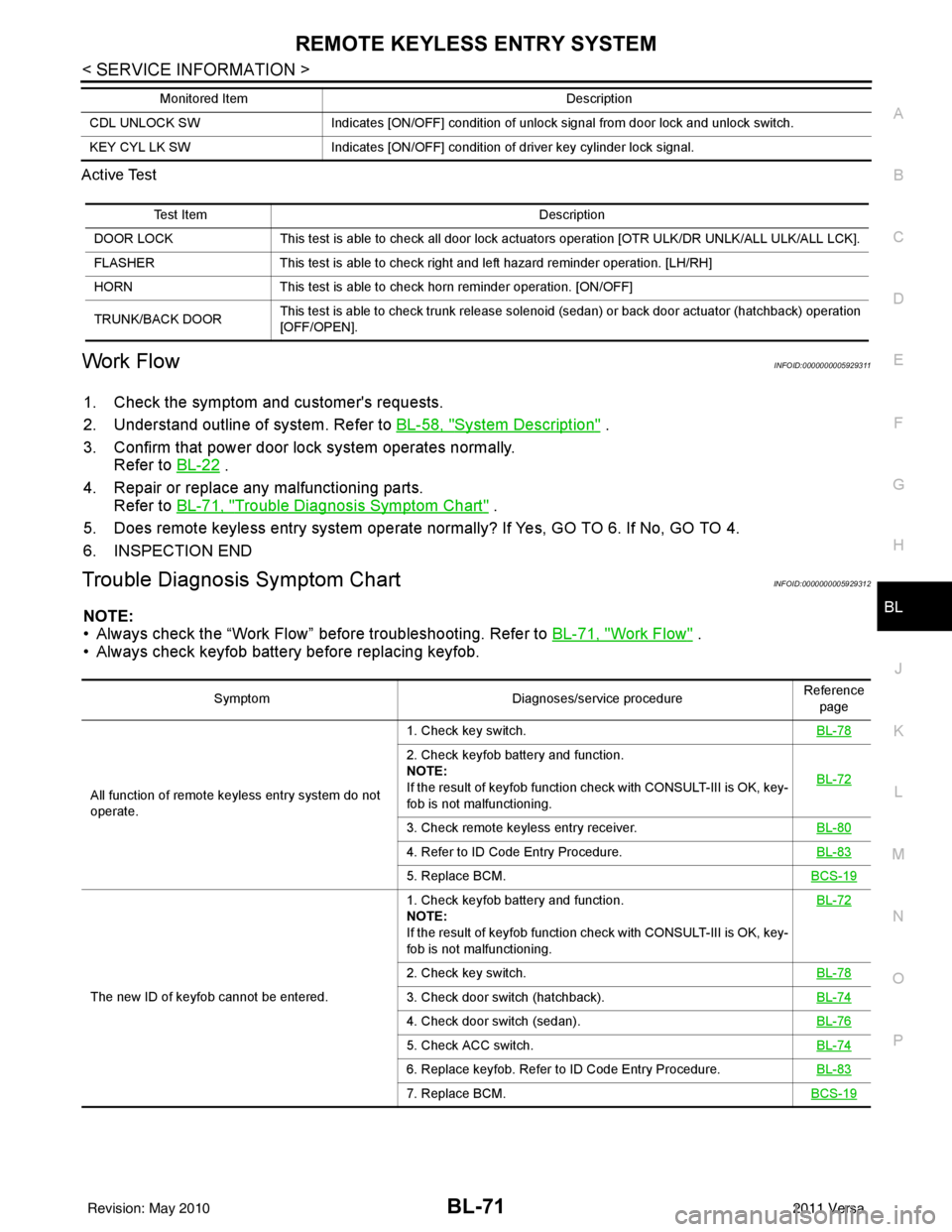
Active Test
Work FlowINFOID:0000000005929311
1. Check the symptom and customer's requests.
2. Understand outline of system. Refer to
BL-58, "
System Description" .
3. Confirm that power door lock system operates normally. Refer to BL-22
.
4. Repair or replace any malfunctioning parts. Refer to BL-71, "
Trouble Diagnosis Symptom Chart" .
5. Does remote keyless entry system operate normally? If Yes, GO TO 6. If No, GO TO 4.
6. INSPECTION END
Trouble Diagnosis Symptom ChartINFOID:0000000005929312
NOTE:
• Always check the “Work Flow” before troubleshooting. Refer to BL-71, "
Work Flow" .
• Always check keyfob battery before replacing keyfob.
CDL UNLOCK SW Indicates [ON/OFF] condition of unlock signal from door lock and unlock switch.
KEY CYL LK SW Indicates [ON/OFF] condition of driver key cylinder lock signal.
Monitored Item
Description
Test ItemDescription
DOOR LOCK This test is able to check all door lock actuators operation [OTR ULK/DR UNLK/ALL ULK/ALL LCK].
FLASHER This test is able to check right and left hazard reminder operation. [LH/RH]
HORN This test is able to check horn reminder operation. [ON/OFF]
TRUNK/BACK DOOR This test is able to check trunk release solenoid (sedan) or back door actuator (hatchback) operation
[OFF/OPEN].
Symptom
Diagnoses/service procedureReference
page
All function of remote keyless entry system do not
operate. 1. Check key switch.
BL-78
2. Check keyfob battery and function.
NOTE:
If the result of keyfob function check with CONSULT-III is OK, key-
fob is not malfunctioning.BL-72
3. Check remote keyless entry receiver.
BL-80
4. Refer to ID Code Entry Procedure.BL-83
5. Replace BCM.BCS-19
The new ID of keyfob cannot be entered.1. Check keyfob battery and function.
NOTE:
If the result of keyfob function check with CONSULT-III is OK, key-
fob is not malfunctioning.
BL-72
2. Check key switch.
BL-78
3. Check door switch (hatchback).BL-74
4. Check door switch (sedan).BL-76
5. Check ACC switch.BL-74
6. Replace keyfob. Refer to ID Code Entry Procedure.BL-83
7. Replace BCM.BCS-19
Revision: May 2010 2011 Versa
Page 619 of 3787

INTELLIGENT KEY SYSTEMBL-109
< SERVICE INFORMATION >
C
DE
F
G H
J
K L
M A
B
BL
N
O P
17 W Rear bumper antenna
(+) signal
LOCK Press back door request switch.
18 B Rear bumper antenna
(-) signal
19 V Front outside antenna
LH (+) signal
LOCK Press door request switch LH.
20 P Front outside antenna
LH (-) signal
22
*2BR Key interlock solenoid — With Intelligent Key present or mechanical
key in ignition cylinder, press "PUSH" but-
ton on ignition cylinder.
Battery voltage
Other than above 0
23 LG Back door open output — Back door open (switch closed)
0
Back door closed (switch open) 5
24 V Back door opener
switch —Press and hold back door switch.
0
Other than above 5
25 L Front door request
switch RH —Press front door request switch RH.
0
Other than above 5
26 SB Stop lamp switch —Depress brake pedal
Battery voltage
Other than above 0
27 W Ignition knob switch — Press ignition switch.
Battery voltage
Release ignition switch. 0
28 Y Unlock sensor
(driver side) —Door (driver si
de) is locked. 5
Door (driver side ) is unlocked. 0
29 V Back door request
switch (hatchback)
—Press back door request switch.
0
Other than above 5
Trunk opener request
switch (sedan) —Press trunk opener request switch.
0
Other than above 5
31 BR Steering lock solenoid
ground
——
0
32 GR Steering lock solenoid
communication signal LOCKWhen Intelligent Key is inside vehicle,
press ignition knob switch.
Other than above
5
Terminal
Wire
Color Item Condition
Voltage (V)Approx.
Ignition
Switch
Position Operation or Conditions
SIIA1910J
SIIA1910J
SIIA1911J
Revision: May 2010
2011 Versa
Page 624 of 3787

BL-114
< SERVICE INFORMATION >
INTELLIGENT KEY SYSTEM
426Y Trunk lamp switch Input OFFON (trunk open)
0V
OFF (trunk closed) Battery voltage
43
5R Back door switch Input OFF ON (open) 0V
OFF (closed)
Battery voltage
44
5LG Rear wiper auto stop Input ON Rear wiper operating 0
Rear wiper stopped
Battery
45
7GR Lock switch Input OFFON (lock)
0V
OFF Battery voltage
46
7L Unlock switch Input OFFON (unlock)
0V
OFF Battery voltage
47 BR Front door switch LH Input OFF ON (open)
0V
OFF (closed) Battery voltage
48 O Rear door switch LH Input OFF ON (open)
0V
OFF (closed) Battery voltage
49 P Luggage room lamp Output OFF Any door open (ON)
0V
All doors closed (OFF) Battery voltage
50 SB A/C indicator Output ONA/C OFF
0
A/C ON Battery voltage
53
5R Back door lock assem-
bly (actuator)
Output OFF Back door (open)
Battery voltage
53
6R Trunk lamp switch and
trunk release solenoid Output OFF Trunk lid (open)
Battery voltage
55
5V Rear wiper motor out-
put
Output ONOFF
0
ON Battery voltage
56 R Battery saver output Output OFF
15 minutes after ignition
switch is turned OFF 0V
ON — Battery voltage
57 LG Battery power supply Input OFF —Battery voltage
59
7G Front door lock actua-
tor LH (unlock)
Output OFFOFF (neutral)
0V
ON (unlock) Battery voltage
60 V Turn signal (left) Output ON Turn left ON
61 W Turn signal (right) Output ON Turn right ON
Te r m i n a l
Wire
color Signal name Signal
input/
output Measuring condition
Reference value or waveform
(Approx.)
Ignition
switch Operation or condition
SKIA3009J
SKIA3009J
Revision: May 2010
2011 Versa