2011 NISSAN LATIO trunk release
[x] Cancel search: trunk releasePage 2363 of 3787
TRUNK LID FINISHEREI-33
< ON-VEHICLE REPAIR >
C
DE
F
G H
J
K L
M A
B
EI
N
O P
TRUNK LID FINISHER
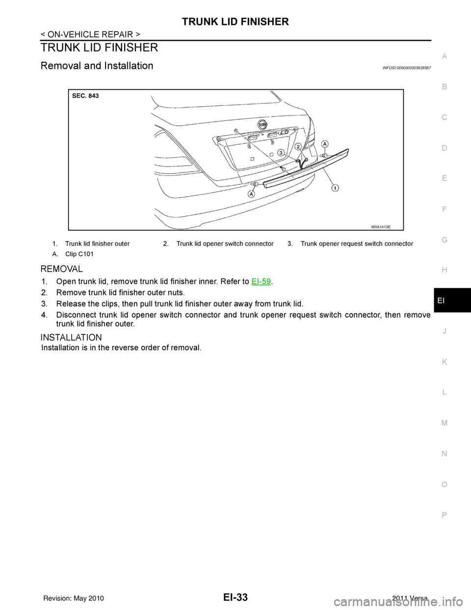
Removal and InstallationINFOID:0000000005929567
REMOVAL
1. Open trunk lid, remove trunk lid finisher inner. Refer to EI-59.
2. Remove trunk lid finisher outer nuts.
3. Release the clips, then pull trunk lid finisher outer away from trunk lid.
4. Disconnect trunk lid opener switch connector and trunk opener request switch connector, then remove trunk lid finisher outer.
INSTALLATION
Installation is in the reverse order of removal.
1. Trunk lid finisher outer 2. Trunk lid opener switch connector 3. Trunk opener request switch connector
A. Clip C101
WIIA1413E
Revision: May 2010 2011 Versa
Page 2365 of 3787
REAR AIR SPOILEREI-35
< ON-VEHICLE REPAIR >
C
DE
F
G H
J
K L
M A
B
EI
N
O P
2. Remove inside trunk lid finisher. Refer to EI-59, "Removal and Installation".
3. Disconnect high mounted stop lamp connector.
4. Release adhesive backed foam tape and clips, then carefully lift the rear air spoiler from trunk lid. CAUTION:
Use care not to damage painted surfaces during removal, or releasing of adhesive backed foam
tapes if equipped.
5. Release the high mounted stop lamp harness grommet from trunk lid, then remove rear air spoiler.
Installation - Sedan
Installation is in the reverse order of removal.
NOTE:
• Before installing rear air spoiler, clean the surface where it will be mounted with isopropyl alcohol or equiva-
lent to degrease the surface.
• Before installing, be sure there are no gaps or wa ves in the foam tape (if equipped) where the surfaces
meet.
• During installation, be sure grommet of high mounted stop lamp harness is fully seated into trunk lid opening prior to final rear air spoiler placement.
Removal - Hatchback
1. Remove back door finisher upper. Refer to EI-40.
2. Disconnect high mounted stop lamp connector.
3. Remove the nuts and carefully lift the rear air spoiler from the back door. CAUTION:
Use care not to damage painted surfaces during removal, or releasing of adhesive backed foam
tapes if equipped.
4. Release the high mounted stop lamp harness grommet from back door, then remove rear air spoiler.
Installation - Hatchback
Installation is in the reverse order of removal.
NOTE:
• Before installing rear air spoiler, clean the surface where it will be mounted with isopropyl alcohol or equiva-
lent to degrease the surface.
• Before installing, be sure there are no gaps or wa ves in the foam tape (if equipped) where the surfaces
meet.
• During installation, be sure grommet of high mount ed stop lamp harness is fully seated into back door open-
ing prior to final rear air spoiler placement.
Revision: May 2010 2011 Versa
Page 2389 of 3787
TRUNK ROOM TRIM & TRUNK LID FINISHEREI-59
< ON-VEHICLE REPAIR >
C
DE
F
G H
J
K L
M A
B
EI
N
O P
TRUNK ROOM TRIM & TRUNK LID FINISHER
Removal and InstallationINFOID:0000000005929579
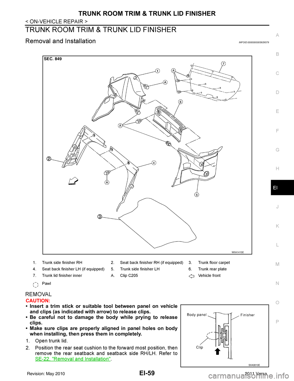
REMOVAL
CAUTION:
• Insert a trim stick or suitable tool between panel on vehicle and clips (as indicated with arrow) to release clips.
• Be careful not to damage the body while prying to release clips.
• Make sure clips are properly al igned in panel holes on body
when installing, then press them in completely.
1. Open trunk lid.
2. Position the rear seat cushion to the forward most position, then remove the rear seatback and seatback side RH/LH. Refer to
SE-22, "
Removal and Installation".
1. Trunk side finisher RH 2. Seat back finisher RH (if equipped) 3. Trunk floor carpet
4. Seat back finisher LH (if equipped) 5. Trunk side finisher LH 6. Trunk rear plate
7. Trunk lid finisher inner A. Clip C205 Vehicle front
Pawl
WIIA1415E
SIIA0810E
Revision: May 2010 2011 Versa
Page 2390 of 3787

EI-60
< ON-VEHICLE REPAIR >
TRUNK ROOM TRIM & TRUNK LID FINISHER
3. Release the clips, then remove the seatback finisher RH/LH.
4. Lift and remove the trunk floor carpet.
5. Release the clips, then remove the trunk rear plate.
6. Release the clips, then remove the trunk side finisher RH/LH.
7. Release the clips and remove the trunk lid finisher inner from the trunk lid.
INSTALLATION
Installation is in the reverse order of removal.
Revision: May 20102011 Versa
Page 2722 of 3787
GI-18
< SERVICE INFORMATION >
HOW TO USE THIS MANUAL
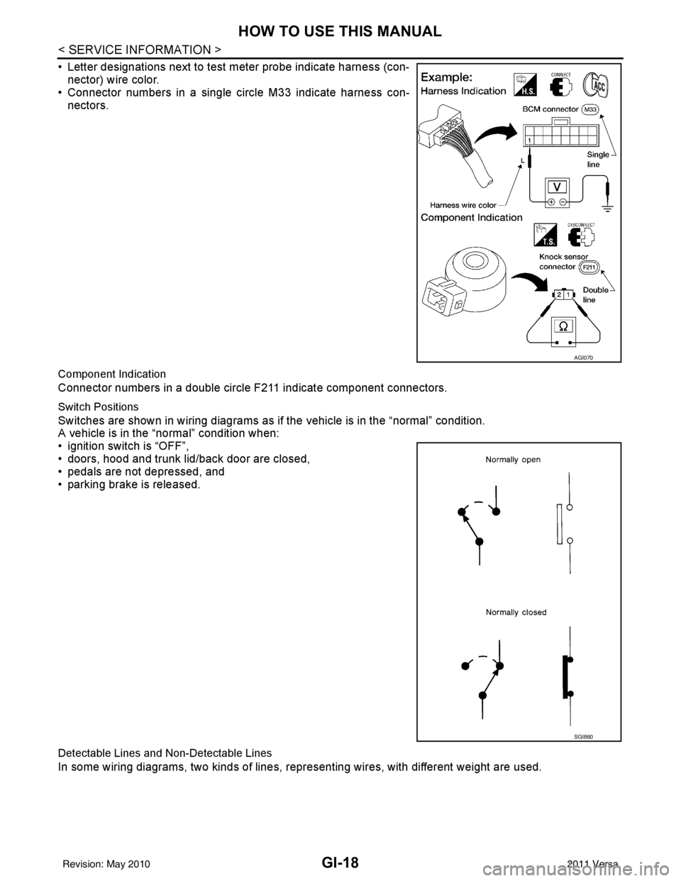
• Letter designations next to test meter probe indicate harness (con-nector) wire color.
• Connector numbers in a single circle M33 indicate harness con-
nectors.
Component Indication
Connector numbers in a double circle F211 indicate component connectors.
Switch Positions
Switches are shown in wiring diagrams as if the vehicle is in the “normal” condition.
A vehicle is in the “normal” condition when:
• ignition switch is “OFF”,
• doors, hood and trunk lid/back door are closed,
• pedals are not depressed, and
• parking brake is released.
Detectable Lines and Non-Detectable Lines
In some wiring diagrams, two kinds of lines, r epresenting wires, with different weight are used.
AGI070
SGI860
Revision: May 2010 2011 Versa
Page 3125 of 3787
INTERIOR ROOM LAMPLT-93
< SERVICE INFORMATION >
C
DE
F
G H
I
J
L
M A
B
LT
N
O P
INTERIOR ROOM LAMP
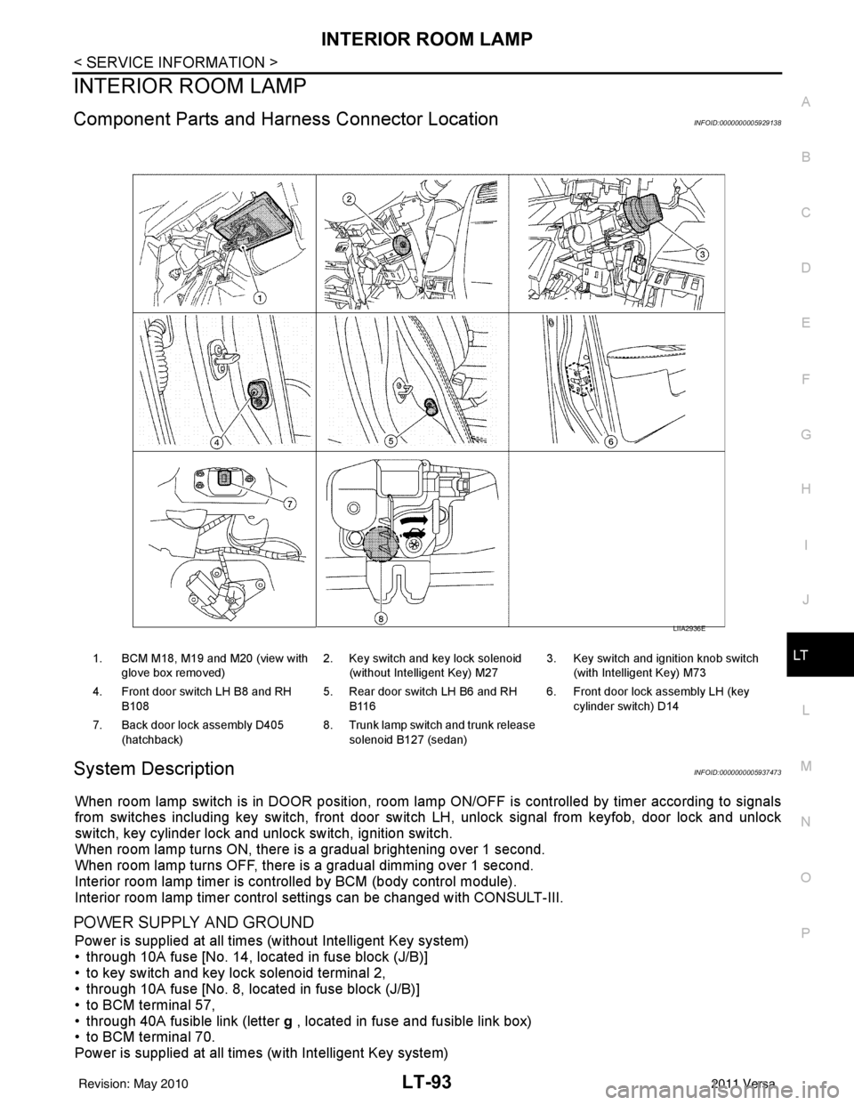
Component Parts and Har ness Connector LocationINFOID:0000000005929138
System DescriptionINFOID:0000000005937473
When room lamp switch is in DOOR position, room la mp ON/OFF is controlled by timer according to signals
from switches including key switch, front door switch LH, unlock signal from keyfob, door lock and unlock
switch, key cylinder lock and unlock switch, ignition switch.
When room lamp turns ON, there is a gradual brightening over 1 second.
When room lamp turns OFF, there is a gradual dimming over 1 second.
Interior room lamp timer is controlled by BCM (body control module).
Interior room lamp timer control settings can be changed with CONSULT-III.
POWER SUPPLY AND GROUND
Power is supplied at all times (without Intelligent Key system)
• through 10A fuse [No. 14, located in fuse block (J/B)]
• to key switch and key lock solenoid terminal 2,
• through 10A fuse [No. 8, located in fuse block (J/B)]
• to BCM terminal 57,
• through 40A fusible link (letter g , located in fuse and fusible link box)
• to BCM terminal 70.
Power is supplied at all times (with Intelligent Key system)
1. BCM M18, M19 and M20 (view with
glove box removed) 2. Key switch and key lock solenoid
(without Intelligent Key) M27 3. Key switch and ignition knob switch
(with Intelligent Key) M73
4. Front door switch LH B8 and RH B108 5. Rear door switch LH B6 and RH
B116 6. Front door lock assembly LH (key
cylinder switch) D14
7. Back door lock assembly D405 (hatchback) 8. Trunk lamp switch and trunk release
solenoid B127 (sedan)
LIIA2936E
Revision: May 2010 2011 Versa
Page 3126 of 3787

LT-94
< SERVICE INFORMATION >
INTERIOR ROOM LAMP
• through 10A fuse (No. 31, located in fuse and fusible link box)
• to key switch and ignition knob switch terminals 2 and 4,
• through 10A fuse [No. 8, located in fuse block (J/B)]
• to BCM terminal 57,
• through 40A fusible link (letter g , located in fuse and fusible link box)
• to BCM terminal 70.
When key is inserted in the key switch and key lock so lenoid, power is supplied (without Intelligent Key sys-
tem)
• through key switch and key lock solenoid terminal 1
• to BCM terminal 37.
When key is inserted in the key switch and ignition knob switch, power is supplied (with Intelligent Key system)
• through key switch and ignition knob switch terminal 1
• to BCM terminal 37.
When ignition knob switch is pushed, power is supplied (with Intelligent Key system)
• through key switch and ignition knob switch terminal 3
• to Intelligent Key unit terminal 27.
With the ignition switch in the ON or START position, power is supplied
• through 10A fuse [No. 6, located in fuse block (J/B)]
• to BCM terminal 38.
Ground is supplied
• to BCM terminal 67
• through grounds M57 and M61.
When front door LH is opened, ground is supplied
• to BCM terminal 47
• through front door switch LH terminal 2
• through case ground of front door switch LH.
When front door RH is opened, ground is supplied
• to BCM terminal 12
• through front door switch RH terminal 2
• through case ground of front door switch RH.
When rear door LH is opened, ground is supplied
• to BCM terminal 48
• through rear door switch LH terminal 1
• through case ground of rear door switch LH.
When rear door RH is opened, ground is supplied
• to BCM terminal 13
• through rear door switch RH terminal 1
• through case ground of rear door switch RH.
When back door (hatchback) is opened, ground is supplied
• to BCM terminal 43
• through back door lock assembly (back door switch) terminal 3
• through back door lock assembly (back door switch) terminal 4
• through grounds B117, B132 and D402.
When trunk lid (sedan) is opened, ground is supplied
• to BCM terminal 42
• through trunk lamp switch and trunk release solenoid terminal 3
• through trunk lamp switch and trunk release solenoid terminal 1
• through grounds B117 and B132.
When front door LH is unlocked by front door lock asse mbly LH (key cylinder switch), the BCM receives a
ground signal
• to BCM terminal 7
• through front door lock assembly LH (key cylinder switch) terminal 5
• through front door lock assembly LH (key cylinder switch) terminal 4
• through grounds M57 and M61.
When a signal, or combination of signals is received by BCM, ground is supplied
• to room lamp terminal 2
• through map lamp terminals 5 and 2 (with map lamp)
• through BCM terminal 63.
With power and ground supplied, the interior room lamp illuminates.
SWITCH OPERATION
When map lamp switch is ON (with map lamp), ground is supplied
Revision: May 2010 2011 Versa
Page 3178 of 3787
GENERAL MAINTENANCEMA-7
< SERVICE INFORMATION >
C
DE
F
G H
I
J
K
M A
B
MA
N
O P
GENERAL MAINTENANCE
Explanation of Gene ral MaintenanceINFOID:0000000005931129
General MaintenanceINFOID:0000000005931130
General maintenance includes those items which shoul d be checked during the normal day-to-day operation
of the vehicle. They are essential if the vehicle is to continue operating properly. The owners can perform
checks and inspections themselves or have their NISSAN dealers do them.
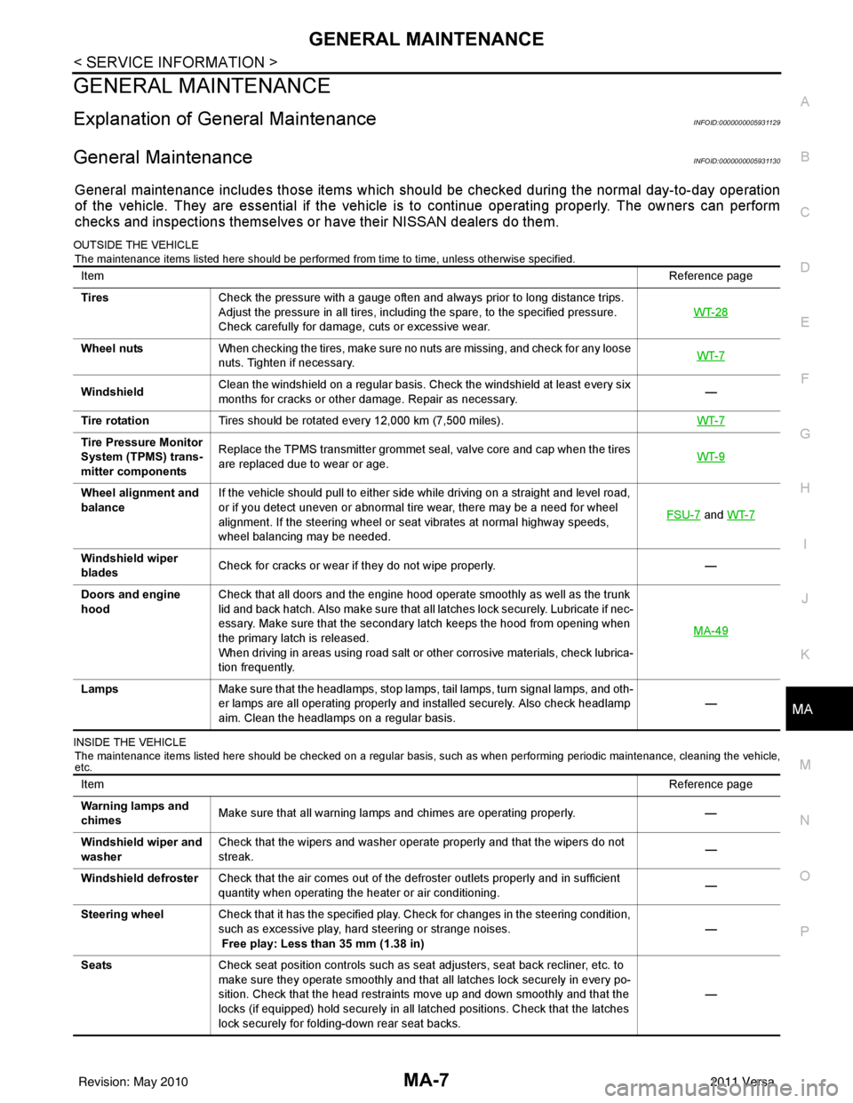
OUTSIDE THE VEHICLE
The maintenance items listed here should be performed from time to time, unless otherwise specified.
INSIDE THE VEHICLE The maintenance items listed here should be checked on a regular basis, such as when performing periodic maintenance, cleaning the vehicle,
etc.
Item Reference page
Tires Check the pressure with a gauge often and always prior to long distance trips.
Adjust the pressure in all tires, including the spare, to the specified pressure.
Check carefully for damage, cuts or excessive wear. WT-28
Wheel nuts
When checking the tires, make sure no nuts are missing, and check for any loose
nuts. Tighten if necessary. WT-7
WindshieldClean the windshield on a regular basis. Check the windshield at least every six
months for cracks or other damage. Repair as necessary.
—
Tire rotation Tires should be rotated every 12,000 km (7,500 miles). WT-7
Tire Pressure Monitor
System (TPMS) trans-
mitter componentsReplace the TPMS transmitter grommet seal, valve core and cap when the tires
are replaced due to wear or age.
WT-9
Wheel alignment and
balanceIf the vehicle should pull to either side while driving on a straight and level road,
or if you detect uneven or abnormal tire wear, there may be a need for wheel
alignment. If the steering wheel or seat vibrates at normal highway speeds,
wheel balancing may be needed. FSU-7
and
WT-7
Windshield wiper
blades Check for cracks or wear if they do not wipe properly.
—
Doors and engine
hood Check that all doors and the engine hood operate smoothly as well as the trunk
lid and back hatch. Also make sure that all latches lock securely. Lubricate if nec-
essary. Make sure that the secondary latch keeps the hood from opening when
the primary latch is released.
When driving in areas using road salt or other corrosive materials, check lubrica-
tion frequently. MA-49
Lamps
Make sure that the headlamps, stop lamps, tail lamps, turn signal lamps, and oth-
er lamps are all operating properly and installed securely. Also check headlamp
aim. Clean the headlamps on a regular basis. —
Item
Reference page
Warning lamps and
chimes Make sure that all warning lamps and chimes are operating properly.
—
Windshield wiper and
washer Check that the wipers and washer operate properly and that the wipers do not
streak.
—
Windshield defroster Check that the air comes out of the defroster outlets properly and in sufficient
quantity when operating the heater or air conditioning. —
Steering wheel Check that it has the specified play. Check for changes in the steering condition,
such as excessive play, hard steering or strange noises.
Free play: Less than 35 mm (1.38 in) —
Seats Check seat position controls such as seat adjusters, seat back recliner, etc. to
make sure they operate smoothly and that all latches lock securely in every po-
sition. Check that the head restraints move up and down smoothly and that the
locks (if equipped) hold securely in all latched positions. Check that the latches
lock securely for folding-down rear seat backs. —
Revision: May 2010
2011 Versa