2011 NISSAN LATIO trunk release
[x] Cancel search: trunk releasePage 725 of 3787
TRUNK LID OPENERBL-215
< SERVICE INFORMATION >
C
DE
F
G H
J
K L
M A
B
BL
N
O P
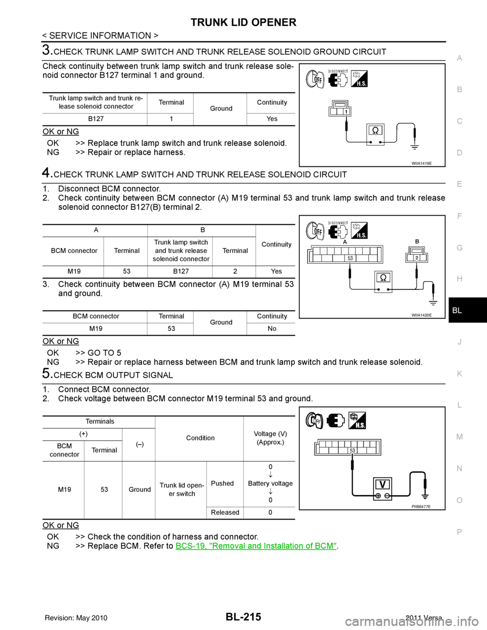
3.CHECK TRUNK LAMP SWITCH AND TRUNK RELEASE SOLENOID GROUND CIRCUIT
Check continuity between trunk lamp switch and trunk release sole-
noid connector B127 terminal 1 and ground.
OK or NG
OK >> Replace trunk lamp switch and trunk release solenoid.
NG >> Repair or replace harness.
4.CHECK TRUNK LAMP SWITCH AND T RUNK RELEASE SOLENOID CIRCUIT
1. Disconnect BCM connector.
2. Check continuity between BCM connector (A) M19 terminal 53 and trunk lamp switch and trunk release solenoid connector B127(B) terminal 2.
3. Check continuity between BCM connector (A) M19 terminal 53 and ground.
OK or NG
OK >> GO TO 5
NG >> Repair or replace harness between BCM and trunk lamp switch and trunk release solenoid.
5.CHECK BCM OUTPUT SIGNAL
1. Connect BCM connector.
2. Check voltage between BCM connector M19 terminal 53 and ground.
OK or NG
OK >> Check the condition of harness and connector.
NG >> Replace BCM. Refer to BCS-19, "
Removal and Installation of BCM".
Trunk lamp switch and trunk re-
lease solenoid connector Te r m i n a l
GroundContinuity
B127 1 Yes
WIIA1419E
AB
Continuity
BCM connector Terminal Trunk lamp switch
and trunk release
solenoid connector Te r m i n a l
M19 53B127 2Yes
BCM connector Terminal
GroundContinuity
M19 53 No
WIIA1420E
Te r m i n a l s
ConditionVoltage (V)
(Approx.)
(+)
(–)
BCM
connector Te r m i n a l
M19 53 Ground Trunk lid open-
er switch Pushed 0
↓
Battery voltage ↓0
Released 0
PIIB6477E
Revision: May 2010 2011 Versa
Page 728 of 3787
BL-218
< SERVICE INFORMATION >
VEHICLE SECURITY (THEFT WARNING) SYSTEM
System Description
INFOID:0000000005929412
DESCRIPTION
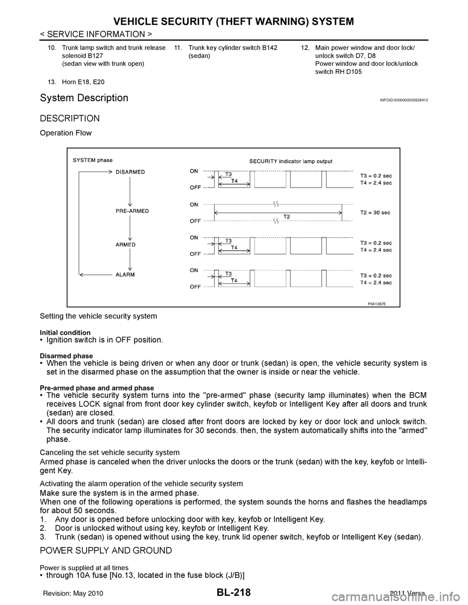
Operation Flow
Setting the vehicle security system
Initial condition• Ignition switch is in OFF position.
Disarmed phase• When the vehicle is being driven or when any door or trunk (sedan) is open, the vehicle security system is
set in the disarmed phase on the assumption that the owner is inside or near the vehicle.
Pre-armed phase and armed phase• The vehicle security system turns into the "pre-armed" phase (security lamp illuminates) when the BCM receives LOCK signal from front door key cylinder switch, keyfob or Intelligent Key after all doors and trunk
(sedan) are closed.
• All doors and trunk (sedan) are closed after front doors are locked by key or door lock and unlock switch.
The security indicator lamp illuminates for 30 seconds. then, the system automatically shifts into the "armed"
phase.
Canceling the set vehicle security system
Armed phase is canceled when the driver unlocks the doors or the trunk (sedan) with the key, keyfob or Intelli-
gent Key.
Activating the alarm operation of the vehicle security system
Make sure the system is in the armed phase.
When one of the following operations is performed, the system sounds the horns and flashes the headlamps
for about 50 seconds.
1. Any door is opened before unlocking door with key, keyfob or Intelligent Key.
2. Door is unlocked without using key, keyfob or Intelligent Key.
3. Trunk (sedan) is opened without using the key, trunk lid opener switch, keyfob or Intelligent Key (sedan).
POWER SUPPLY AND GROUND
Power is supplied at all times• through 10A fuse [No.13, located in the fuse block (J/B)]
10. Trunk lamp switch and trunk release
solenoid B127
(sedan view with trunk open) 11. Trunk key cylinder switch B142
(sedan) 12. Main power window and door lock/
unlock switch D7, D8
Power window and door lock/unlock
switch RH D105
13. Horn E18, E20
PIIA1367E
Revision: May 2010 2011 Versa
Page 739 of 3787

VEHICLE SECURITY (THEFT WARNING) SYSTEMBL-229
< SERVICE INFORMATION >
C
DE
F
G H
J
K L
M A
B
BL
N
O P
426Y Trunk lamp switch Input OFF ON (trunk open)
0V
OFF (trunk closed) Battery voltage
43
5R Back door switch Input OFF ON (open) 0V
OFF (closed)
Battery voltage
44
5LG Rear wiper auto stop Input ON Rear wiper operating 0
Rear wiper stopped
Battery
45
7GR Lock switch Input OFFON (lock)
0V
OFF Battery voltage
46
7L Unlock switch Input OFFON (unlock)
0V
OFF Battery voltage
47 BR Front door switch LH Input OFF ON (open)
0V
OFF (closed) Battery voltage
48 O Rear door switch LH Input OFF ON (open)
0V
OFF (closed) Battery voltage
49 P Luggage room lamp Output OFF Any door open (ON)
0V
All doors closed (OFF) Battery voltage
50 SB A/C indicator Output ONA/C OFF
0
A/C ON Battery voltage
53
5R Back door lock assem-
bly (actuator)
Output OFF Back door (open)
Battery voltage
53
6R Trunk lamp switch and
trunk release solenoid Output OFF Trunk lid (open)
Battery voltage
55
5V Rear wiper motor out-
put
Output ONOFF
0
ON Battery voltage
56 R Battery saver output Output OFF
15 minutes after ignition
switch is turned OFF 0V
ON — Battery voltage
57 LG Battery power supply Input OFF —Battery voltage
59
7G Front door lock actua-
tor LH (unlock)
Output OFFOFF (neutral)
0V
ON (unlock) Battery voltage
60 V Turn signal (left) Output ON Turn left ON
61 W Turn signal (right) Output ON Turn right ON
Te r m i n a l
Wire
color Signal name Signal
input/
output Measuring condition
Reference value or waveform
(Approx.)
Ignition
switch Operation or condition
SKIA3009J
SKIA3009J
Revision: May 2010
2011 Versa
Page 752 of 3787
BL-242
< SERVICE INFORMATION >
VEHICLE SECURITY (THEFT WARNING) SYSTEM
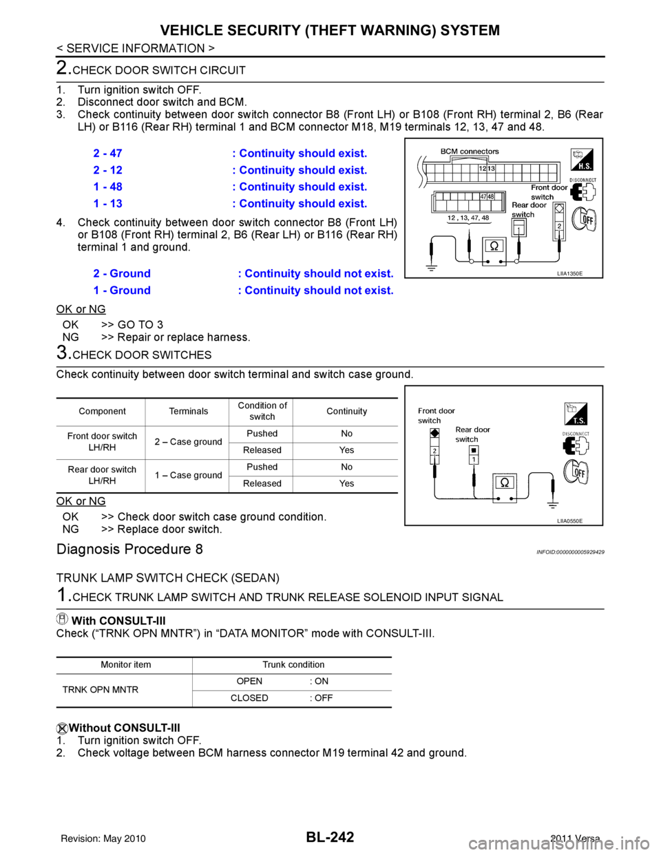
2.CHECK DOOR SWITCH CIRCUIT
1. Turn ignition switch OFF.
2. Disconnect door switch and BCM.
3. Check continuity between door switch connector B8 (F ront LH) or B108 (Front RH) terminal 2, B6 (Rear
LH) or B116 (Rear RH) terminal 1 and BCM connector M18, M19 terminals 12, 13, 47 and 48.
4. Check continuity between door switch connector B8 (Front LH) or B108 (Front RH) terminal 2, B6 (Rear LH) or B116 (Rear RH)
terminal 1 and ground.
OK or NG
OK >> GO TO 3
NG >> Repair or replace harness.
3.CHECK DOOR SWITCHES
Check continuity between door switch terminal and switch case ground.
OK or NG
OK >> Check door switch case ground condition.
NG >> Replace door switch.
Diagnosis Procedure 8INFOID:0000000005929429
TRUNK LAMP SWITCH CHECK (SEDAN)
1.CHECK TRUNK LAMP SWITCH AND TRUNK RELEASE SOLENOID INPUT SIGNAL
With CONSULT-III
Check (“TRNK OPN MNTR”) in “DATA MONITOR” mode with CONSULT-III.
Without CONSULT-III
1. Turn ignition switch OFF.
2. Check voltage between BCM harness connector M19 terminal 42 and ground. 2 - 47
: Continuity should exist.
2 - 12 : Continuity should exist.
1 - 48 : Continuity should exist.
1 - 13 : Continuity should exist.
2 - Ground : Continuity should not exist.
1 - Ground : Continuity should not exist.
LIIA1350E
Component Terminals Condition of
switch Continuity
Front door switch LH/RH 2 – Case ground Pushed
No
Released Yes
Rear door switch LH/RH 1 – Case ground Pushed
No
Released Yes
LIIA0550E
Monitor item Trunk condition
TRNK OPN MNTR OPEN
: ON
CLOSED : OFF
Revision: May 2010 2011 Versa
Page 753 of 3787
VEHICLE SECURITY (THEFT WARNING) SYSTEMBL-243
< SERVICE INFORMATION >
C
DE
F
G H
J
K L
M A
B
BL
N
O P
OK or NG
OK >> Trunk lamp switch and trunk release solenoid circuit is OK.
NG >> GO TO 2
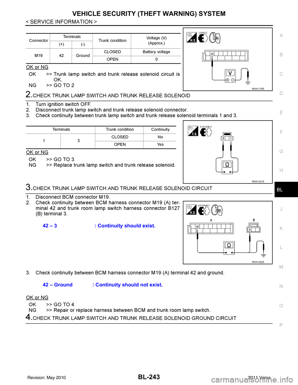
2.CHECK TRUNK LAMP SWITCH A ND TRUNK RELEASE SOLENOID
1. Turn ignition switch OFF.
2. Disconnect trunk lamp switch and trunk release solenoid connector.
3. Check continuity between trunk lamp switch and trunk release solenoid terminals 1 and 3.
OK or NG
OK >> GO TO 3
NG >> Replace trunk lamp switch and trunk release solenoid.
3.CHECK TRUNK LAMP SWITCH AND T RUNK RELEASE SOLENOID CIRCUIT
1. Disconnect BCM connector M19.
2. Check continuity between BCM harness connector M19 (A) ter- minal 42 and trunk room lamp switch harness connector B127
(B) terminal 3.
3. Check continuity between BCM harness connector M19 (A) terminal 42 and ground.
OK or NG
OK >> GO TO 4
NG >> Repair or replace harness between BCM and trunk room lamp switch.
4.CHECK TRUNK LAMP SWITCH AND TRUNK RELEASE SOLENOID GROUND CIRCUIT
Connector Te r m i n a l s
Trunk condition Voltage (V)
(Approx.)
(+) (-)
M19 42 Ground CLOSED
Battery voltage
OPEN 0
WIIA1179E
Terminals Trunk condition Continuity
13 CLOSED
No
OPEN Yes
WIIA1421E
42 – 3: Continuity should exist.
WIIA1422E
42 – Ground : Continuity should not exist.
Revision: May 2010 2011 Versa
Page 754 of 3787
BL-244
< SERVICE INFORMATION >
VEHICLE SECURITY (THEFT WARNING) SYSTEM
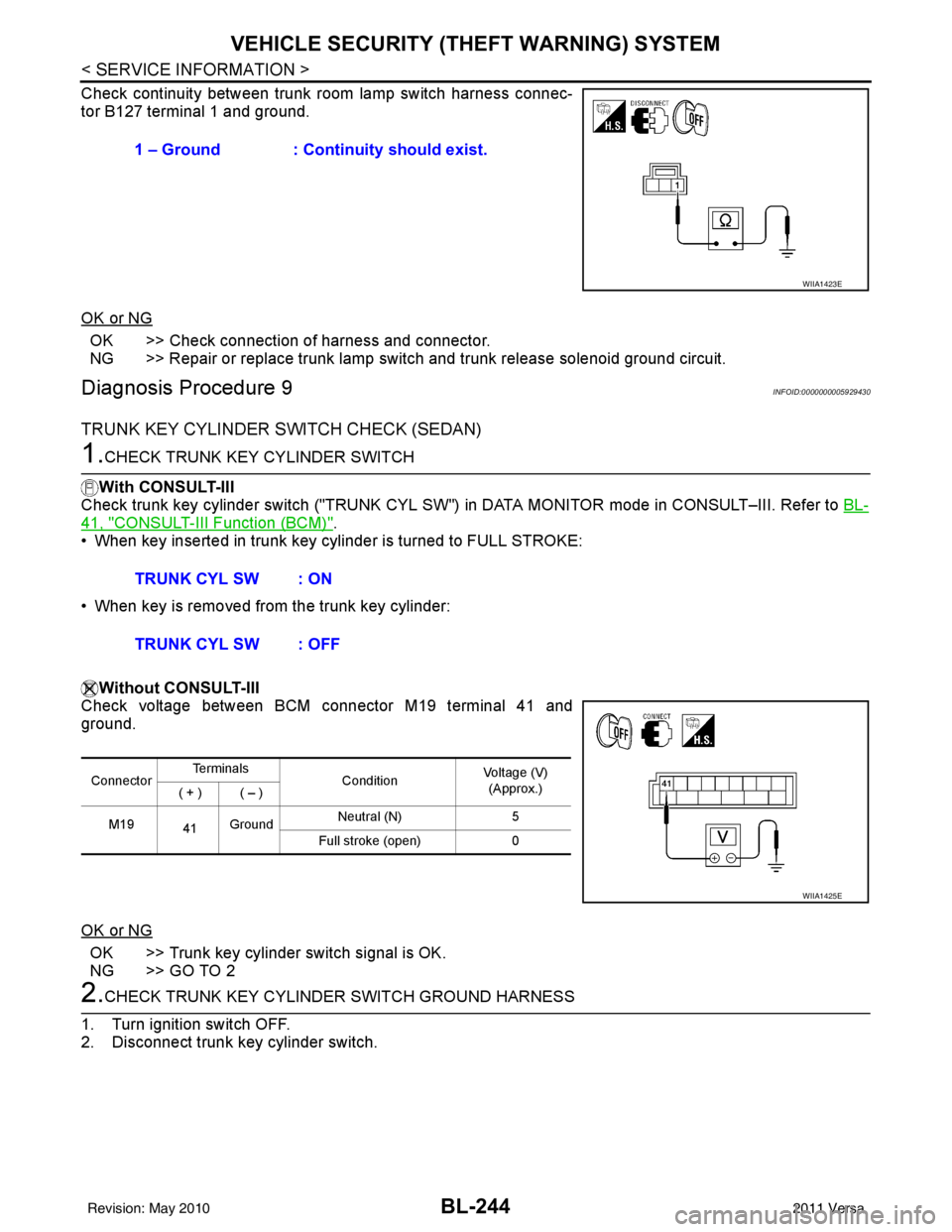
Check continuity between trunk room lamp switch harness connec-
tor B127 terminal 1 and ground.
OK or NG
OK >> Check connection of harness and connector.
NG >> Repair or replace trunk lamp switch and trunk release solenoid ground circuit.
Diagnosis Procedure 9INFOID:0000000005929430
TRUNK KEY CYLINDER SWITCH CHECK (SEDAN)
1.CHECK TRUNK KEY CYLINDER SWITCH
With CONSULT-III
Check trunk key cylinder switch ("TRUNK CYL SW") in DATA MONITOR mode in CONSULT–III. Refer to BL-
41, "CONSULT-III Function (BCM)".
• When key inserted in trunk key cylinder is turned to FULL STROKE:
• When key is removed from the trunk key cylinder:
Without CONSULT-III
Check voltage between BCM connector M19 terminal 41 and
ground.
OK or NG
OK >> Trunk key cylinder switch signal is OK.
NG >> GO TO 2
2.CHECK TRUNK KEY CYLINDE R SWITCH GROUND HARNESS
1. Turn ignition switch OFF.
2. Disconnect trunk key cylinder switch. 1 – Ground : Continuity should exist.
WIIA1423E
TRUNK CYL SW : ON
TRUNK CYL SW : OFF
Connector
Te r m i n a l s
ConditionVoltage (V)
(Approx.)
( + ) ( – )
M19 41Ground Neutral (N)
5
Full stroke (open) 0
WIIA1425E
Revision: May 2010 2011 Versa
Page 763 of 3787

NATS (NISSAN ANTI-THEFT SYSTEM)BL-253
< SERVICE INFORMATION >
C
DE
F
G H
J
K L
M A
B
BL
N
O P
426Y Trunk lamp switch Input OFF ON (trunk open)
0V
OFF (trunk closed) Battery voltage
43
5R Back door switch Input OFF ON (open) 0V
OFF (closed)
Battery voltage
44
5LG Rear wiper auto stop Input ON Rear wiper operating 0
Rear wiper stopped
Battery
45
7GR Lock switch Input OFFON (lock)
0V
OFF Battery voltage
46
7L Unlock switch Input OFFON (unlock)
0V
OFF Battery voltage
47 BR Front door switch LH Input OFF ON (open)
0V
OFF (closed) Battery voltage
48 O Rear door switch LH Input OFF ON (open)
0V
OFF (closed) Battery voltage
49 P Luggage room lamp Output OFF Any door open (ON)
0V
All doors closed (OFF) Battery voltage
50 SB A/C indicator Output ONA/C OFF
0
A/C ON Battery voltage
53
5R Back door lock assem-
bly (actuator)
Output OFF Back door (open)
Battery voltage
53
6R Trunk lamp switch and
trunk release solenoid Output OFF Trunk lid (open)
Battery voltage
55
5V Rear wiper motor out-
put
Output ONOFF
0
ON Battery voltage
56 R Battery saver output Output OFF
15 minutes after ignition
switch is turned OFF 0V
ON — Battery voltage
57 LG Battery power supply Input OFF —Battery voltage
59
7G Front door lock actua-
tor LH (unlock)
Output OFFOFF (neutral)
0V
ON (unlock) Battery voltage
60 V Turn signal (left) Output ON Turn left ON
61 W Turn signal (right) Output ON Turn right ON
Te r m i n a l
Wire
color Signal name Signal
input/
output Measuring condition
Reference value or waveform
(Approx.)
Ignition
switch Operation or condition
SKIA3009J
SKIA3009J
Revision: May 2010
2011 Versa
Page 2351 of 3787
REAR BUMPEREI-21
< ON-VEHICLE REPAIR >
C
DE
F
G H
J
K L
M A
B
EI
N
O P
Removal and Installation - SedanINFOID:0000000005929557
REMOVAL
1. Open trunk lid.
2. Remove rear combination lamp RH/LH. Refer to LT-88, "
Removal and Installation".
3. Remove rear bumper fascia spring nuts and screws RH/LH.
4. Remove rear fender protector. Refer to EI-26, "
Removal and Installation".
5. Pull the rear bumper fascia side outward and release the bumper side bracket.
6. Remove rear bumper fascia upper clips and screws.
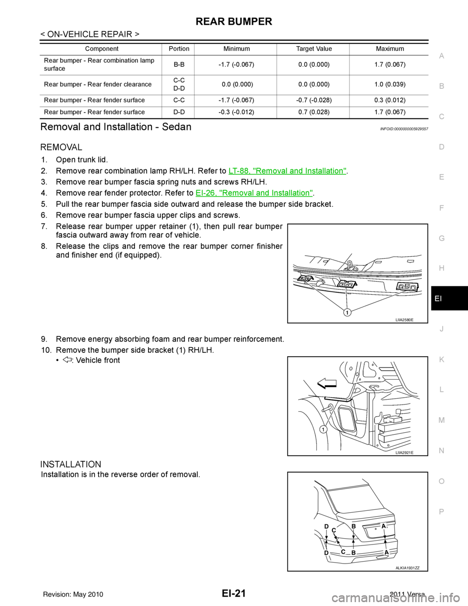
7. Release rear bumper upper retainer (1), then pull rear bumper fascia outward away from rear of vehicle.
8. Release the clips and remove the rear bumper corner finisher and finisher end (if equipped).
9. Remove energy absorbing foam and rear bumper reinforcement.
10. Remove the bumper side bracket (1) RH/LH. • : Vehicle front
INSTALLATION
Installation is in the reverse order of removal.
Rear bumper - Rear combination lamp
surface B-B
-1.7 (-0.067) 0.0 (0.000)1.7 (0.067)
Rear bumper - Rear fender clearance C-C
D-D
0.0 (0.000)
0.0 (0.000)1.0 (0.039)
Rear bumper - Rear fender surface C-C -1.7 (-0.067)-0.7 (-0.028) 0.3 (0.012)
Rear bumper - Rear fender surface D-D -0.3 (-0.012)0.7 (0.028)1.7 (0.067)
Component
PortionMinimum Target Value Maximum
LIIA2580E
LIIA2921E
ALKIA1931ZZ
Revision: May 2010 2011 Versa