Page 153 of 196
Replacing componentsMobility
151
Replacing a fog lamp bulb
H8 bulb, 35 watts
1.Turn in the wheel.
2. Remove cover 2.
To do so, turn the cover counterclockwise.
3. Pull the cable connector.
4. Unscrew the lower bulb counterclockwise.
5. To insert the new bulb and replace the
cover, proceed in reverse order.
Side turn signals
5watt bulb, W5W
1.Open hood.
2. Squeeze clamping clip, arrows, and remove
bulb holder.
3. Unscrew bulb counterclockwise and
replace.
4. To insert the new bulb and replace the
cover, proceed in reverse order.
Side marker lamps
Have these bulbs replaced by your MINI dealer.
Tail lamps
Bulb P 21 W
1Brake/tail lamp
2 Turn signal
3 Brake/tail lamp
4 Backup lamps
5 Backup lamps
Changing
All bulbs are integrated in a central bulb holder.
1.Switch off the light and remove the infrared
remote control from the ignition lock.
2. Push the cover panel out from the rear of the
cargo area side trim panel and remove it.
Page 154 of 196

MobilityReplacing components
152
3.Disengage the bulb holder by pressing down
on the clamping clip, arrow.
4. Remove bulb holder.
5. Apply gentle pressure to the bulb while turn-
ing it to the left for removal and replace-
ment.
6. Re-engage the bulb holder so that it audibly
clicks into place.
7. Replace the cover panel.
License plate lamps
5 watt bulb, C 5 W
1.Using a screwdriver, push the lamp to the
left in the tab of the lamp housing, arrow 1.
2. Remove the lamp, arrow 2.
3. Replace the bulb.
4. Insert the lamp.
Center brake lamp
This lamp uses LED techno logy for operation. In
the event of a malfunction, contact your MINI
dealer or a workshop th at has specially trained
personnel working in acco rdance with the spec-
ifications of your MINI manufacturer.
Repairing a flat tire
Safety measures in the event of a break-
down:
Park the vehicle as far as possible from moving
traffic and switch on the hazard warning flash-
ers.
Turn the steering wheel until the front wheels
are in the straight-ahead position and engage
the steering wheel lock. Engage the parking
brake and shift into 1st or reverse gear or place
the selector leve r in position P.
All passengers should be outside the vehicle and
in a safe place, e.g. behind a guardrail.
Erect a warning triangle or warning flasher at the
appropriate distance if necessary. Comply with
all safety guidelines and regulations. <
In the event of a flat ti re, different procedures
should be followed depending on the equip-
ment included in your vehicle:
> MINI Mobility System, refer to the following
section
> Run-flat tires, page 136
MINI Mobility System*
The Mobility System is located under the left
front seat.
Preparations
Use of the MINI Mobility System may be ineffec-
tive if the tire puncture measures approx. 1/8 in/
4 mm or more. Contact the nearest MINI dealer
if the tire cannot be made drivable with the
Mobility System.
Do not remove foreign bodies which have pen-
etrated the tire if possible.
Follow the instructions on using the Mobil-
ity System found on the compressor and
the sealant bottle. <
Remove the adhesive label for the speed limit
from the sealant bottle an d affix it to the steer-
ing wheel.
Page 155 of 196

Replacing componentsMobility
153
Sealant and compressor
1Sealant bottle and adhesi ve label with speed
limit
2 Filling hose
Note the use-by date on the sealant bot-
tle. <
3 Holder for the sealant bottle
4 Compressor
5 Plug and cable for the socket in the vehicle
interior, page 86
6 Connection hose to connect the compressor
and sealant bottle or the compressor and
wheel
7 On/off switch
8 Pressure gauge for indi cating the tire infla-
tion pressure
9 Release button for reduci ng the tire inflation
pressure
Connector, cable and connection hose are
stored in the compressor housing.
Using the Mobility System
To repair a tire puncture with the Mobility Sys-
tem, proceed as follows:
> Filling the tire with sealant
> Distributing the sealant
> Correct the tire inflation pressure
Filling the tire with sealant
Proceed in the specified order; otherwise,
sealant may emerge under high pres-
sure. <
1. Shake the sealant bottle.
2. Pull the connecting hose 6 completely out of
the compressor housing and screw it onto
the connector of the sealant bottle. Make
sure that the hose is not kinked.
3. Insert the sealant bottle on the compressor
housing in an upright position.
4. Unscrew the dust cap from the valve of the
defective wheel and screw the filling hose 2
of the sealant bottle onto the valve.
5. Ensure that the compressor is switched off.
6. Insert the plug 5 into the lighter socket/
power socket in the vehicle interior,
page 86.
7. With the engine running:
Switch on the compresso r and let it run for
approx. 3 to 8 minutes to fill the tire with
sealant and achieve a ti re inflation pressure
of approx. 26 psi/180 kPa.
When filling with the sealant, the infla-
tion pressure can briefly rise to
Page 156 of 196

MobilityReplacing components
154
approx. 73 psi/500 kPa. Do not switch off
the compressor during this phase.<
Do not run the comp ressor for longer
than 10 minutes; otherwise, the
device will overheat and possibly be dam-
aged.<
8. Switch off the compressor.
If an air pressure of 26 psi/180 kPa is not
reached:
1. Unscrew the filling hose 2 from the wheel
and drive the vehicle forward and backward
approx. 33 ft/10 m to distribute the liquid
sealant in the tire evenly.
2. Inflate the tire again with the compressor.
If an inflation pressure of 26 psi/180 kPa
still cannot be reache d, the tire is too
heavily damaged. Please contact the nearest
MINI dealer. <
Stowing Mobility System
1.Unscrew filler hose 2 of the sealant bottle
from the wheel.
2. Unscrew connecting hose of the
compressor 6 from the sealant bottle.
3. Connect the filler hose 2 of the sealant bot-
tle to the unoccupied connection on the
sealant bottle.
This prevents the rest of the sealant from
escaping from the bottle.
4. Wrap the empty sealant bottle in suitable
material to avoid dirt ying the cargo area.
5. Stow Mobility System back in the vehicle.
Distributing the sealant
Immediately drive approx. 3 miles/5 km so that
the sealant evenly distributes itself.
Do not exceed speeds of 50 mph/
80 km/h.
If possible, do not drop below 10 mph/
20 km/h. <
Correct the tire inflation pressure
1.After driving approx. 3 miles/5 km or ten
minutes, stop at a suitable location.
2. Screw the connection hose 6 of the com-
pressor directly onto the tire valve.
3. Insert the plug 5 into the power socket in
the vehicle interior.
4. Correct inflation pressu re to 26 psi/180 kPa.
With the engine running:
> To increase the inflatio n pressure: switch on
the compressor. To ch eck the current infla-
tion pressure, switch off the compressor.
Do not run the compressor for longer
than 10 minutes; otherwise, the
device will overheat and possibly be dam-
aged.<
> To decrease the inflat ion pressure: press the
release button 9.
If the tire cannot m aintain the inflation
pressure, drive the vehicle again, refer to
Distributing the sealan t. Then repeat steps
1to4.
If an inflation pressure of 26 psi/180 kPa still
cannot be reached, the tire is too heavily dam-
aged. Contact the nearest MINI dealer. <
Driving on
Do not exceed the permitted maximum
speed of 50 mph/80 km/h; doing so may
result in an accident. <
Replace the defective tire as soon as possible
and have the new wheel/tire assembly bal-
anced.
Have the Mobility System refilled.
Page 157 of 196

Replacing componentsMobility
155
Changing wheels
The pouch with the wheel changing kit* is
stored under the flat load floor
*. It includes:
> Vehicle jack
> Reversible ratchet
> Wheel stud wrench
> Extractor hook for wheel center cover
> Chock
Preparing for a wheel change
Observe the safety precautions regarding
flat tires on page 152.<
Additional safety measures when chang-
ing tires:
Only change the tire when parked on a surface
that is level, firm and not slippery.
The vehicle or the jack could slip sideways on
soft or slippery support surfaces, such as snow,
ice, flagstones, etc.
Do not use a wooden block or similar object as a
support base for the jack, as this would prevent
it from extending to its full support height and
reduce its load-carrying capacity.
Do not lie under the vehicle or start the engine
when the vehicle is supported by the jack; other-
wise, there is a risk of fatal injury. <
1. Place the foldable chock
* behind the front
wheel on the other side of the vehicle or in
front of the wheel if the vehicle is on an
incline. If the wheel is changed on a surface
with a more severe slope, take additional
precautions to secure the vehicle from roll-
ing.
2. Uncover the lug bolts if necessary.
3. Loosen the lug bolts by a half turn.
Jacking up the vehicle
The vehicle jack is designed for changing
wheels only. Do not attempt to raise
another vehicle model with it or to raise any load
of any kind. To do so could cause accidents and
personal injury. < 1.
Place the jack at the jacking point closest to
the wheel.
The jack base must be perpendicular to the
surface beneath the jacking point.
2. Slide reversible ratchet onto the fixture on
the jack, arrow 1.
3. As you ratchet up the jack, place the jack
head onto the lifting point on the body,
arrow 2.
4. Jack the vehicle up until the wheel you are
changing is raised off the ground.
Mounting the wheel
1.Unscrew the lug bolts and remove the
wheel.
2. Remove accumulations of mud or dirt from
the mounting surfaces of the wheel and
hub. Clean the lug bolts.
3. Lift the new wheel into place.
4. Screw at least two lug bo lts finger-tight into
opposite bolt holes.
5. Screw in the remaining bolts.
6. Tighten all the lug bolts firmly in a diagonal
pattern.
Page 158 of 196

MobilityReplacing components
156
7.Lower the vehicle.
8. Remove the jack.
Tightening the lug bolts
Tighten the lug bolts in a diagonal pattern.
Immediately have the wheels checked
with a calibrated torque wrench to ensure
that the lug bolts are firmly seated. Otherwise,
incorrectly tightened lu g bolts can present a
safety hazard. <
Tightening torque: 103.3 lb ft or 140 Nm.
Replace the defective tire as soon as possible
and have the new wheel/tire assembly bal-
anced.
Vehicle battery
Maintenance
The battery is 100 % maintenance-free, the
electrolyte will last for the life of the battery
when the vehicle is operated in a temperate cli-
mate.
Battery replacement
Only use vehicle batteries that have been
approved for your vehicle by the manu-
facturer; otherwise, the vehicle could be dam-
aged and systems or func tions may not be fully
available. <
After a battery replacement, have the battery
registered on the vehicle by your dealer to
ensure that all comfort functions are fully avail-
able.
Charging the battery
Only charge the battery in the vehicle when the
engine is off. Connectio ns, refer to Jump-start-
ing on page 158.
Disposal
After replacing old ba tteries, return the
used batteries to your MINI dealer or to a
recycling center. Maintain the battery in an
upright position for transport and storage.
Always secure the battery against tipping over
during transport. <
Power failure
After a temporary power loss, some equipment
may not be fully functional and may require ini-
tialization. Individual se ttings are also lost and
must be reprogrammed:
> Time and date
These values must be updated, page 57.
> Radio
In some cases, stations may have to be
stored again, page 104.
> Glass sunroof
*, electric
It may only be possible to tilt the sunroof, if
applicable. The system must be initialized.
Contact your near est MINI dealer.
Fuses
Do not attempt to repair a blown fuse or
replace it with a fuse of a different color or
Ampere rating. To do this could cause a fire in
the vehicle resulting from a circuit overload.
Have the fuse changed only by a MINI dealer or
a workshop that has specially trained personnel
working in accordance with the specifications of
the MINI manufacturer. <
A fuse allocation diagram is located on the inside
of the fuse box cover panels.
Page 159 of 196
Replacing componentsMobility
157
In the engine compartment
Opening the cover
Press the latch.
In the vehicle interior
On the right side of the footwell.
Opening the cover
Press out at the recess.
Page 160 of 196

MobilityGiving and receiving assistance
158
Giving and receiving assistance
Roadside Assistance
Roadside Assistance is available by phone
24 hours a day in many countries. You can
obtain assistance there in the event of a vehicle
breakdown.
First aid pouch*
Some of the articles co ntained in the first aid
pouch have a limited service life. Therefore,
check the expiration dates of the contents regu-
larly and replace any item s in good time, if nec-
essary.
The first aid pouch is located on the rear cargo
well by the left side trim panel or under the pull-
out floor panel.
Warning triangle*
In the cargo area under the loading sill.
To remove, open the two clasps.
Jump-starting
If the car's own battery is flat, your MINI's engine
can be started by connecting two jumper cables
to another vehicle's battery. You can also use
the same method to help start another vehicle.
Only use jumper cables with fully-insulated
clamp handles.
Do not touch any electrically live parts
wh en t he e ngine is run nin g, or a fatal acci-
dent may occur. Carefully adhere to the follow-
ing sequence, both to prevent damage to one or
both vehicles, and to guard against possible per-
sonal injuries. <
Preparation
1.Check whether the battery of the other vehi-
cle has a voltage of 12 volts and approxi-
mately the same capa citance in Ah. This
information can be found on the battery.
2. Switch off the engine of the support vehicle.
3. Switch off any consumers in both vehicles.
There must not be any contact between
the bodies of the two vehicles; otherwise,
there is a danger of shorting. <
 1
1 2
2 3
3 4
4 5
5 6
6 7
7 8
8 9
9 10
10 11
11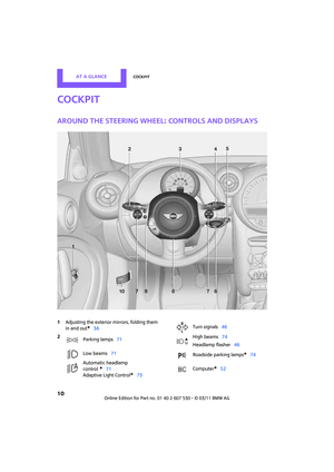 12
12 13
13 14
14 15
15 16
16 17
17 18
18 19
19 20
20 21
21 22
22 23
23 24
24 25
25 26
26 27
27 28
28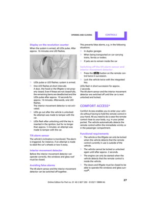 29
29 30
30 31
31 32
32 33
33 34
34 35
35 36
36 37
37 38
38 39
39 40
40 41
41 42
42 43
43 44
44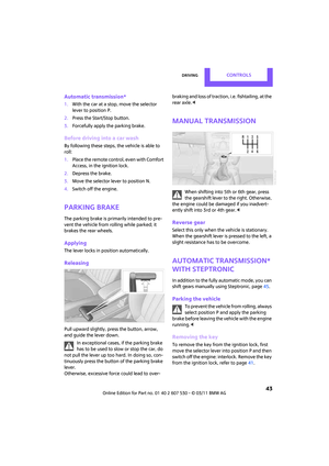 45
45 46
46 47
47 48
48 49
49 50
50 51
51 52
52 53
53 54
54 55
55 56
56 57
57 58
58 59
59 60
60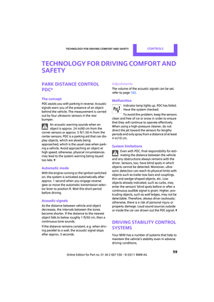 61
61 62
62 63
63 64
64 65
65 66
66 67
67 68
68 69
69 70
70 71
71 72
72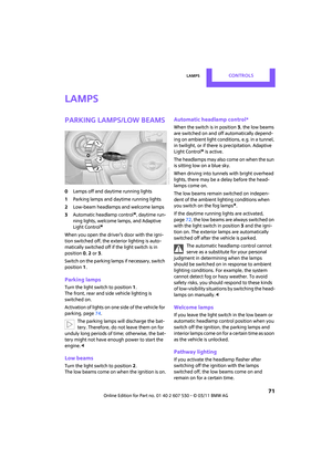 73
73 74
74 75
75 76
76 77
77 78
78 79
79 80
80 81
81 82
82 83
83 84
84 85
85 86
86 87
87 88
88 89
89 90
90 91
91 92
92 93
93 94
94 95
95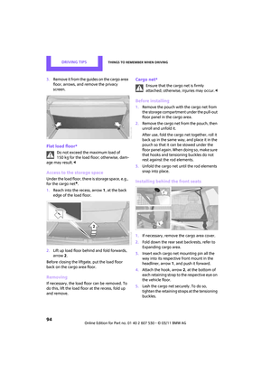 96
96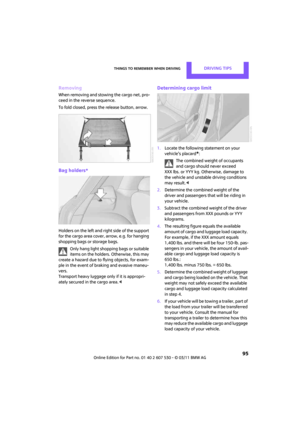 97
97 98
98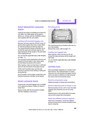 99
99 100
100 101
101 102
102 103
103 104
104 105
105 106
106 107
107 108
108 109
109 110
110 111
111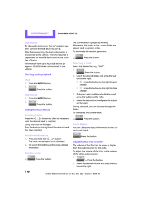 112
112 113
113 114
114 115
115 116
116 117
117 118
118 119
119 120
120 121
121 122
122 123
123 124
124 125
125 126
126 127
127 128
128 129
129 130
130 131
131 132
132 133
133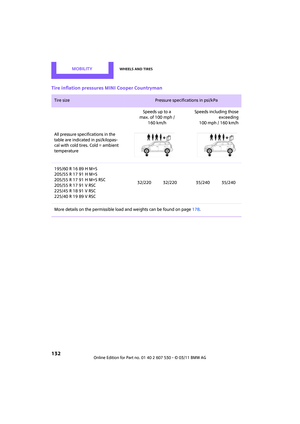 134
134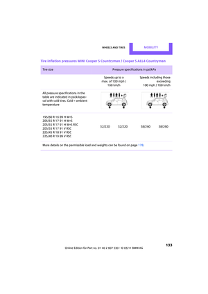 135
135 136
136 137
137 138
138 139
139 140
140 141
141 142
142 143
143 144
144 145
145 146
146 147
147 148
148 149
149 150
150 151
151 152
152 153
153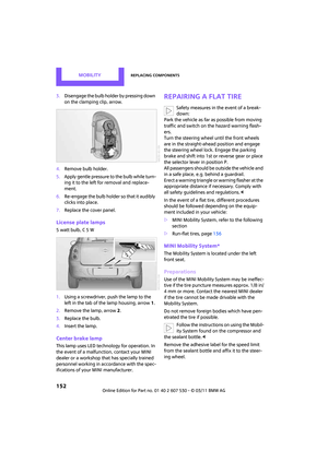 154
154 155
155 156
156 157
157 158
158 159
159 160
160 161
161 162
162 163
163 164
164 165
165 166
166 167
167 168
168 169
169 170
170 171
171 172
172 173
173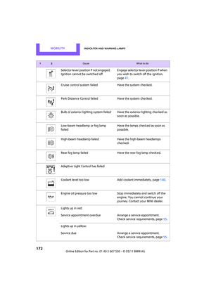 174
174 175
175 176
176 177
177 178
178 179
179 180
180 181
181 182
182 183
183 184
184 185
185 186
186 187
187 188
188 189
189 190
190 191
191 192
192 193
193 194
194 195
195
